EP1716084B1 - Verfahren zur herstellung einer dämpfungsarmen lichtleitfaser - Google Patents
Verfahren zur herstellung einer dämpfungsarmen lichtleitfaser Download PDFInfo
- Publication number
- EP1716084B1 EP1716084B1 EP03808316A EP03808316A EP1716084B1 EP 1716084 B1 EP1716084 B1 EP 1716084B1 EP 03808316 A EP03808316 A EP 03808316A EP 03808316 A EP03808316 A EP 03808316A EP 1716084 B1 EP1716084 B1 EP 1716084B1
- Authority
- EP
- European Patent Office
- Prior art keywords
- preform
- central hole
- core preform
- zone
- glass
- Prior art date
- Legal status (The legal status is an assumption and is not a legal conclusion. Google has not performed a legal analysis and makes no representation as to the accuracy of the status listed.)
- Expired - Lifetime
Links
Images



Classifications
-
- C—CHEMISTRY; METALLURGY
- C03—GLASS; MINERAL OR SLAG WOOL
- C03B—MANUFACTURE, SHAPING, OR SUPPLEMENTARY PROCESSES
- C03B37/00—Manufacture or treatment of flakes, fibres, or filaments from softened glass, minerals, or slags
- C03B37/01—Manufacture of glass fibres or filaments
- C03B37/012—Manufacture of preforms for drawing fibres or filaments
- C03B37/014—Manufacture of preforms for drawing fibres or filaments made entirely or partially by chemical means, e.g. vapour phase deposition of bulk porous glass either by outside vapour deposition [OVD], or by outside vapour phase oxidation [OVPO] or by vapour axial deposition [VAD]
- C03B37/01446—Thermal after-treatment of preforms, e.g. dehydrating, consolidating, sintering
-
- C—CHEMISTRY; METALLURGY
- C03—GLASS; MINERAL OR SLAG WOOL
- C03B—MANUFACTURE, SHAPING, OR SUPPLEMENTARY PROCESSES
- C03B37/00—Manufacture or treatment of flakes, fibres, or filaments from softened glass, minerals, or slags
- C03B37/01—Manufacture of glass fibres or filaments
- C03B37/012—Manufacture of preforms for drawing fibres or filaments
- C03B37/014—Manufacture of preforms for drawing fibres or filaments made entirely or partially by chemical means, e.g. vapour phase deposition of bulk porous glass either by outside vapour deposition [OVD], or by outside vapour phase oxidation [OVPO] or by vapour axial deposition [VAD]
- C03B37/01466—Means for changing or stabilising the diameter or form of tubes or rods
- C03B37/01473—Collapsing
-
- Y—GENERAL TAGGING OF NEW TECHNOLOGICAL DEVELOPMENTS; GENERAL TAGGING OF CROSS-SECTIONAL TECHNOLOGIES SPANNING OVER SEVERAL SECTIONS OF THE IPC; TECHNICAL SUBJECTS COVERED BY FORMER USPC CROSS-REFERENCE ART COLLECTIONS [XRACs] AND DIGESTS
- Y02—TECHNOLOGIES OR APPLICATIONS FOR MITIGATION OR ADAPTATION AGAINST CLIMATE CHANGE
- Y02P—CLIMATE CHANGE MITIGATION TECHNOLOGIES IN THE PRODUCTION OR PROCESSING OF GOODS
- Y02P40/00—Technologies relating to the processing of minerals
- Y02P40/50—Glass production, e.g. reusing waste heat during processing or shaping
- Y02P40/57—Improving the yield, e-g- reduction of reject rates
Definitions
- the present invention relates to a process for producing a glass core preform for a low-attenuation optical fiber.
- One of the most important characteristics of a telecommunication optical fiber is the signal attenuation in particular wavelength regions currently used for long-distance transmission. In fact, the lower is the signal attenuation, the longer the distance the signal can travel before being amplified.
- fiber attenuation is negatively affected by the presence of impurities, which can be incorporated within the fiber during the process of manufacturing thereof. Particularly troublesome is the attenuation caused by contamination by hydroxyl radicals (OH) or water.
- the attenuation increase due to the presence of OH or water in the glass can be as high as about 0.5 to 1.0 dB/km, with a peak in the wavelength range from 1330 nm to 1470 nm (commonly identified as "1380 nm window”), making this range unsuitable for long-distance transmission.
- the most suitable wavelength range for long-distance transmission is still that around 1550 nm, which guarantees very low losses.
- WDM wavelength division multiplexing
- WO 00/64825 in the attempt to solve the above problem, proposes a method of fabricating a cylindrical glass body for use in manufacturing optical waveguide fiber, wherein the incorporation of water is at least reduced.
- WO 00/64825 describes the following process to produce an optical fiber.
- a porous body is made by depositing reaction products on a cylindrical substrate in a conventional Outside Vapor Deposition (OVD) process.
- a centreline hole (or "central hole") extending axially through the porous body is formed by removing the substrate.
- the hollow body so obtained is consolidated in a chlorine-containing atmosphere to chemically dry the blank, thus forming a consolidated glass preform having a centerline hole extending axially therethrough.
- the core glass preform is then typically positioned within a redraw furnace and heated to a temperature sufficient to facilitate redrawing or stretching of the core preform into a smaller diameter cylindrical glass body or core cane.
- the centerline hole of the core blank is closed by, for example, applying vacuum along the centerline hole.
- the reduction in pressure within the centerline hole ensures complete closure of the centerline hole such that the core cane has a solid centerline region extending axially therethrough.
- the resulting core cane is typically overclad with a layer of cladding soot, e.g. deposited via an OVD process.
- the resulting soot overclad core cane is chemically dried and consolidated to form an optical fiber preform, which can thereafter be drawn into an optical waveguide fiber.
- WO 00/64825 proposes either to prevent water exposure of the centerline hole of the dried and consolidated preform by closing the centerline hole during consolidation, or to chemically remove the water after rewetting has occurred, preferably at redraw, by treating the centreline hole with a chemical drying agent, a chemical etching agent or deuterium.
- a glass plug Prior to consolidation of the soot preform, a glass plug is fitted to the end of the centerline hole opposite the end of the soot preform provided with a handle. Following chlorine drying, the porous body (held vertically via the handle) is down driven into the hot zone of the consolidation furnace, preferably in an inert gas atmosphere, such as helium.
- the elevated temperature generated in the hot zone preferably about 1500°C, sinters porous body as it enters the hot zone.
- the inwardly directed sintering forces reduce the diameter of porous body thereby closing porous body onto plug to effectively seal one end of centerline hole.
- the porous body is further down driven to sinter the remainder of porous body thereby forming a sintered glass preform having a centerline hole sealed at its plugged ends.
- the sintered glass preform is preferably withdrawn from the hot zone, and the centerline hole is exposed to a vacuum of at least 10 Torr, more preferably 100 mTorr, through an inner handle, which communicates with centerline hole through the handle.
- the sintered glass preform is again down driven into the hot zone of consolidation furnace while centerline hole is under vacuum.
- centerline hole is under vacuum.
- the sintered glass preform enters the hot zone, it softens sufficiently so that the vacuum force acting on the glass bounding the centerline hole draws the glass inward, thereby closing centerline hole as the sintered glass preform continues to move through the hot zone.
- the resulting solid sintered glass preform can then be removed from consolidation furnace and stored for further processing at a later time, or moved to a redraw furnace where it can be drawn into a reduced diameter cane. In either event, since centerline hole is closed (i. e. , the sintered glass preform has a solid centerline region), the centerline region will not be exposed to ambient atmosphere and thus will not be rewet upon removal from consolidation furnace.
- WO03011779 discloses a method of fabricating an optical waveguide fiber from a preform having a centerline aperture which includes reducing the pressure in the centerline aperture, then increasing the pressure in the centerline aperture to a pressure in order to improve uniformity, circularity, and/or symmetry around the centerline aperture region.
- the Applicant has then found that, by causing only a partial closure of the central hole in the consolidation furnace, and then completing the closure of the central hole in the subsequent step of stretching, the problem of rewetting of the central hole after consolidation is largely reduced and the formation of bubbles and voids is very unlikely.
- the partial closure of the central hole is achieved by subjecting the core preform to a further thermal treatment after the steps of drying and consolidation in the furnace, without extraction of the preform from the furnace between the consolidation and the further thermal treatment.
- the preform upon consolidation of the core preform in the hot zone of a furnace, the preform is extracted from the hot zone but not from the furnace, to avoid exposure to water-containing atmosphere.
- the central hole is then exposed to a vacuum through the handle on top of the consolidated preform.
- the glass preform After raising the temperature of the hot zone to a glass melting temperature, the glass preform is again down driven into the hot zone at a predetermined speed. In such conditions the glass softens enough to get a significant reduction of the internal radius of the central hole, without closure thereof and without any significant stretching of the whole preform due to gravity, thanks to the inward pressure and surface tension of the glass.
- optical fibers with attenuation at 1383 nm lower than 0.35 dB/km can be currently obtained with the disclosed method.
- a significant reduction of internal defects in the core of the final fiber e. g. bubble, voids
- the present invention thus relates to a process for producing a glass core preform for a low-loss (or low-attenuation) optical fiber, the process comprising:
- the step of reducing the diameter of the central hole comprises reducing the pressure inside the central hole and subjecting the glass core preform to a temperature sufficient to soften glass.
- the diameter of the central hole at the end of the drying and consolidation step is more preferably of between 0.05 mm and 0.2 mm.
- the diameter of the central hole at the end of the drying and consolidation step is at most 1: 10 of an initial diameter of the central hole.
- the step of drying and consolidation advantageously includes drying the soot core preform at a first temperature, consolidating the de-hydrated soot core preform at a second temperature higher than the first temperature and subjecting the consolidated core preform to a third temperature higher that the second temperature for reducing said diameter.
- the step of drying and consolidation preferably comprises in sequence the following steps:
- the pressure in the central hole is preferably reduced to at most 200 mBar, more preferably to at most 100 mBar.
- a low-melting temperature member is fit to a lower end of the central hole glass before the step of drying, and then a vacuum pump extracts gas from the central hole from an upper end thereof after the consolidated core preform has been moved from the second zone to the first zone.
- Reducing the diameter of the central hole advantageously comprises subjecting the glass core preform to a temperature between about 1495 °C and 1540 °C. This thermal treatment is performed for a predetermined time.
- reducing the diameter of the central hole preferably comprises subjecting the glass core preform to a temperature sufficient to soften glass for a time comprised between 1 h and 3 h.
- the soot core preform has a core radius and an external radius, the ratio between the core radius and the external radius being preferably lower than about 0.4.
- a process for producing a glass core preform for a glass optical fiber according to the present invention includes the following steps.
- a plurality of chemical substances typically comprising oxides of silicium and germanium, is deposited on a cylindrical mandrel (typically of aluminium) by Outside Vapor Deposition (OVD), using a OVD apparatus of a known type (not shown).
- ODD Outside Vapor Deposition
- the substances so deposited will form the core and an inner cladding portion of the final optical fiber.
- the reactants flow may be varied so as to obtain a predetermined Refractive Index Profile (RIP).
- the ratio between core radius and external radius can be derived from the Refractive Index Profile (RIP) of the core preform, which in turn can be measured on the core canes (resulting from the fourth stage of the process described below) by means of an appropriate preform profile analyser.
- Figure 1 shows the RIP of a core cane realized by the above OVD process, measured by a YORK P106 preform analyser (the zone in grey cannot be detected by the instrument).
- the RIP has indicated on the horizontal axis the core radius (CR) and the external radius (ER).
- the ratio between core radius and external radius should be preferably lower than 0.4, more preferably lower than of 0.38, still more preferably lower than of 0.33, so as to prevent contamination of the core and inner cladding region due to diffusion of OH from the overcladding region.
- the mandrel is extracted from the core preform, leaving a central hole along the longitudinal axis of the core preform.
- Drying and consolidation apparatus 10 comprises a furnace 20 and a preform translation device 15.
- the furnace 20 comprises a lateral wall 29, preferably cylindrical, a basement 30 and a heating system not shown. Lateral wall 29 internally delimits a region for thermal treatment of the preform, including an upper zone 21 and a lower zone 22.
- the furnace 20 is heated in such a way as to show a non-uniform longitudinal temperature profile.
- the temperature in the lower zone 22 is higher than in the upper zone 21, and the lower zone 21 is therefore called also "hot zone".
- the upper zone 21 and the lower zone 22 are used for de-hydration and consolidation of the preform 23, respectively.
- Basement 30 of furnace 20 may be connected to a gas delivery system (not shown) through one or more ducts 28.
- the core preform 23 is provided at one end with a handle 25 and the preform translation device 15 comprises an arm 24 for gripping the handle 25 and holding the preform 23 vertically.
- the preform translation device 15 is suitable to move the preform vertically between an upper position outside the furnace 20 and a lower position within the hot zone 22 of the furnace 20.
- a gas flow passage is provided through arm 24 and handle 25 to allow a drying gas to flow from a gas delivery device (not shown) into the central hole 26 of the preform 23.
- FIG. 3 shows a typical temperature profile 31 within the furnace 20, represented as temperature (left vertical axis) vs. axial position along the furnace (horizontal axis) measured from the top thereof. It can be observed that the temperature in the upper zone 21 is almost constant (i.e. zone 21 is an almost isothermal zone), then rises quite rapidly through a transition zone 19 to reach its highest value in the hot zone 22.
- Figure 3 further shows the position of the preform 23 (represented by a black segment of length proportional to that of the preform) vs. time (right vertical axes) during the dehydration-consolidation process.
- the process starts by coupling arm 24 to handle 25 and by placing the preform 23 in the upper position outside the furnace 20.
- a cylindrical tube 27, made of low-melting temperature glass, is then fitted to the central hole 26 at the bottom of the preform 23.
- the preform 23 is then moved down into the upper zone 21 of the furnace 20.
- One or more drying gases typically including Cl 2 , are fed into the central hole 26 through arm 24 and handle 25, in order to eliminate the hydroxide ions and the water molecules in the preform (drying process).
- Cl 2 a drying gas
- 0.15 l/min of Cl 2 may be fed together with 1.5 l/min of He.
- an inert gas preferably He, is fed through ducts 28 into the furnace 20.
- 80 l/min of He are fed into the furnace 20 at this stage.
- number 32 indicates the position of preform 23 inside the furnace 20 at the beginning of the dehydration process, in which the preform 23 is positioned in the upper zone 21 (in the example here considered, the upper end of the preform is at about 2700 mm from the top of the furnace 20 and the lower end thereof at about 3200 mm from the top of the furnace 20).
- the temperature of the preform grows in a relatively short time to the temperature of curve 31 corresponding to that position, which is of about 1000°C (more precisely, from about 950°C to about 1050°C) in the illustrated example.
- the preform 23 is kept in this position for a predetermined time, such as for example 1 h, to allow complete dehydration thereof.
- Number 33 indicates the preform 23 at the end of this dehydration process (same position but time-shift of 60 min with respect to segment 32).
- Preform 23 is then moved down towards hot zone 22 for the consolidation process, preferably at a constant speed, for example 5 mm/min.
- Number 34 indicates an intermediate position of the preform 23 during lowering, 160 min from the beginning of the process in the illustrated example. In this intermediate position, the ends of the preform 23 are subjected to very different temperatures, since the temperature of furnace 20 varies sharply in that zone (in the illustrated example, the temperatures at the upper and lower ends of the preform 23 are of about 1030°C and 1300°C, respectively).
- the preform 23 starts consolidating (i.e. the soot core preform transforms into a vitrified core preform). Meanwhile, the glass tube 27 melts and seals the lower end of the central hole 26.
- the preform 23 is represented by a dashed line while entering the hot zone 22.
- the furnace 20 is still fed with an inert gas, such as He, preferably at the same flow rate as in the drying stage.
- the temperature in the hot zone 22 may be, for example, of about 1420°C.
- the preform 23 is moved down until it has almost completely crossed the hot zone 22, more precisely until the lower end thereof has exited the hot zone downward and the upper end has entered the hot zone.
- number 35 indicates the position of the preform 23 at completion of the consolidation process, after a predetermined travelling time in zone 22.
- the vitrified core preform 23 is then moved back out of the hot zone 22.
- preform 23 In a conventional process, preform 23 would be completely removed from furnace 20 and the process of drying and consolidation of the core preform would be concluded.
- a typical preform would have, at the end of a conventional process of drying and consolidation, a diameter of the central hole of between 3 mm and 4 mm.
- the preform 23 is not extracted from the furnace after drying and consolidation, and is subjected to a further thermal treatment in the furnace 20 for partial closure of the central hole 26, i.e. for reducing the diameter of the central hole 26 without a complete closure thereof.
- the preform 23 is raised from the hot zone 22 towards the upper zone 21, such as up to the intermediate position 34 in Figure 3 .
- a vacuum is then created inside the central hole 26 through the arm 24 and handle 25 by means of a vacuum pump which extract the gas from the central hole, so as to reduce the pressure in the hole 26 down to a value preferably lower than 200 mBar, more preferably lower than 100 mBar.
- the temperature in the hot zone 22 is raised at a value preferably between 1495°C and 1540°C, more preferably between 1510°C and 1530°C, for example 1520°C.
- the preform 23 is driven down again into the hot zone 22, for example down again to position 35 in Figure 3 , at a speed preferably comprised between 3 mm/min and 4 mm/min, for example of 3.4 mm/min.
- the furnace 20 is still fed with an inert gas, preferably He.
- the flow rate of this inert gas through ducts 28 is preferably lower than in the drying and consolidation stages.
- a suitable flow rate is for example 20 l/min.
- the travelling time of the preform 23 across the hot zone 22 i.e. the time required for a point on the preform to completely cross the hot zone
- the preform 23 may be kept steady for a predetermined time, for example for 15 min, to compensate for the typically larger initial hole diameter on top of the preform. Then, the preform 23 is raised up and finally removed from the furnace 20.
- the diameter of the central hole 26 at the end of this further thermal treatment is lower than 0.4 mm and greater than 0.05 mm, preferably lower than 0.2 mm and greater than 0.05 mm.
- the final diameter is preferably between about 1:10 and about 1:80 the initial diameter, more preferably between about 1:20 and about 1:80 the initial diameter.
- a diameter larger than 0.4 mm could result in a not-negligible OH contamination after extraction of the preform 23 from the furnace 20, while a diameter lower than 0.05 mm could induce premature closure of the hole 26.
- the final hole diameter reached at the end of the further thermal treatment depends on different parameters, including the initial hole diameter, the temperature in the hot zone 22, the pressures inside the central hole 26 and outside the preform 23, and the time of travelling of the preform 23 in the hot zone 22.
- a working value of surface tension ⁇ for glass is 0.3 N/m.
- the difference P 2 -P 1 is nearly 1 bar.
- Viscosity data for silica glass are available in literature. At 1500 °C, viscosity is of about 1.4 10 8 kg/(m sec).
- Figure 4 shows different curves associated with the evolution of the internal radius R 1 vs. temperature T in the hot zone 22, at various travelling times of the preform 23 within the hot zone 22:
- Figure 4 allows identifying a suitable curve. For example, by choosing a final hole diameter between 0.05 mm and 0.2 mm and a hot zone temperature between 1495°C and 1525°C, a rectangular box 49 can be drawn in the diagram, and all the curves intersecting this box identify suitable travelling times. In the present case, intersections of box 49 with curves 42 and 44 show that a suitable travelling time is between 1 hour and 3 hours.
- the process parameters must be set so as to achieve the desired diameter reduction without the complete closure of the central hole 26, in order to prevent formation of voids, bubbles, or similar defects.
- the zone of box 49 is also characterized by a reduced slope of the curves, which means a reduced sensitivity to the process conditions (time and temperature).
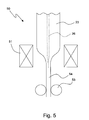
- the consolidated core preform 23 is subjected to a stretching process by means of a stretching apparatus shown schematically in Figure 5 and there indicated with 50.
- the stretching apparatus 50 includes a vertical furnace 51, a preform feeding device (not shown) for feeding the preform 23 into the furnace 51 and a traction device 53 for pulling down the cooled material.
- the stretching process includes creating vacuum inside the reduced-diameter central hole through the handle of the preform 23 (as described, for example, in US 4,810,276 ) and lowering the preform 23 into the vertical furnace 51 for melting a lower end thereof.
- the melt of the lower end of the preform 23 and the vacuum inside the central hole 26 cause the walls of the central hole 26 to collapse to a complete closure.
- the fused glass material exiting the furnace cools, forming a cylindrical elongated glass member 54 of predetermined diameter, which is stretched downwards by the traction device 53.
- the traction device may be of the type described in WO 01/49616 , which is suitable to impart a twist to the elongated glass member 54 during stretching, thus producing a rod-like member with a high degree of straightness.
- the elongated glass member 54 is cut in a plurality of rods, called “core rods” or “core canes”.
- the next stages lead to an optical fiber.
- each core rod is used as a substrate for a further process of OVD chemical deposition of a known type, herein below called "overcladding process".
- the overcladding process comprises depositing SiO 2 on the core rod, to form an outer portion of the preform that will define an outer portion of the cladding of the final fiber.
- This further deposition process may be carried out as described in WO 03/045861 .
- the result of this stage is a fi nal preform having the outer surface of the cladding coaxial to the core.
- a sixth stage herein below identified as “overcladding dehydration-consolidation process” or “final-preform consolidation process”
- the final preform is dried and consolidated by a procedure similar to that of the third stage, thus obtaining a vitrified final preform.
- the same apparatus used for the third stage (apparatus 10) can be used for this stage, as well.
- the final preform is drawn in appropriate drawing towers of a known type, wherein the final preform is supplied, along a vertical direction, to a furnace, so as to obtain melting of a lower portion thereof.
- the molten material is then drawn and cooled so as to obtain an optical fiber with the desired characteristics.
- the Applicant has compared the attenuation of four different fibers F 1 , F 2 , F 3 and F 4 , differing for the characteristics of the core preform, for the conditions in the core-preform consolidation process and for the conditions in the final-preform consolidation process.
- the characteristic of the core preform that has been varied is the ratio between core radius and external radius.
- the ratio between core radius and external radius can be derived from the Refractive Index Profile (RIP) of the core preform, which can be measured on the core cane by means of an appropriate preform profile analyser.
- RIP Refractive Index Profile
- a first core preform which will be referred to as “core preform E” has been produced with a ratio between core radius and external radius of 0.38.
- a second core preform which will be referred to as “core preform F”, has been produced with a ratio between core radius and external radius of 0.44.
- Core preform F is considered to be more subjected to OH contamination from the overcladding than core preform E, since it is easier for the OH ions collected in the overcladding region and still present after drying and consolidation to reach the core region during the high-temperature process of drawing.
- the core-preform consolidation process has been first performed in a conventional way, i.e. with no hole diameter reduction, and according to the present invention, i.e. with hole diameter reduction.
- the conventional process will be referred to as "core-preform consolidation A” the process according to the present invention as “core-preform consolidation B”.
- final-preform consolidation C 0.85 l/min of Cl 2 in 25 l/min of He have been fed from the bottom piping 28, the preform 23 was moved down at a speed of 7 mm/min, and the isothermal zone 21 and hot zone 22 were at 1000 °C and 1500 °C, respectively.
- final-preform consolidation D 1.7 l/min of Cl 2 in 25 l/min of He have been fed from the bottom piping 28, the preform 23 was moved down at a speed of 5 mm/min, and the isothermal zone 21 and hot zone 22 were at 1100 °C and 1500 °C, respectively.
- Fibers F 1 , F 2 , F 3 and F 4 were made as reported in Table I.
- Table I Core preform Core-preform consolidation Final-preform consolidation F 1 F A C F 2 F B C F 3 E B C F 4 E B D
- Figure 6 shows the cumulative distribution of the peak attenuation at 1383 nm for fibers F 1 , F 2 , F 3 and F 4 .
- the results are summarized in terms of average values in Table II, together with the averages at 1310 nm.
- Table II att @ 1383 nm att @ 1310 nm F+A+C 0.59 0.336 F+B+C 0.49 0.332 E+B+C 0.38 0.327 E+B+D 0.32 0.326
- the number of defects detected in the preforms from process B is less than half those found in the preforms from process A.
Landscapes
- Chemical & Material Sciences (AREA)
- Engineering & Computer Science (AREA)
- Geochemistry & Mineralogy (AREA)
- Life Sciences & Earth Sciences (AREA)
- General Chemical & Material Sciences (AREA)
- General Life Sciences & Earth Sciences (AREA)
- Chemical Kinetics & Catalysis (AREA)
- Manufacturing & Machinery (AREA)
- Materials Engineering (AREA)
- Organic Chemistry (AREA)
- Physics & Mathematics (AREA)
- Thermal Sciences (AREA)
- Manufacture, Treatment Of Glass Fibers (AREA)
Claims (12)
- Verfahren zum Herstellen einer Glaskernvorform (54) einer dämpfungsarmen Lichtleitfaser, wobei der Prozess umfasst:- Herstellen einer Rußkernvorform durch chemische Ablagerungen auf einem Substrat;- Entfernen des Substrats von der Rußkernvorform, wodurch ein Mittelloch (26) entlang der Rußkernvorform (23) gebildet wird;- Trocknen und Verdichten der Rußkernvorform (23) in einem Ofen (20), um die Glaskernvorform (23) zu bilden, und- Strecken der Glaskernvorform (23);wobei der Schritt des Trocknens und Verdichtens umfasst Reduzieren des Durchmessers des Mittellochs (26) ohne Extrahieren der Glaskernvorform von dem Ofen (20) und der Schritt des Streckens umfasst Schließen des Mittellochs (26), wobei der Prozess gekennzeichnet ist dadurch, dass der Durchmesser des Mittellochs (26) am Ende des Trocknungs- und Verdichtungsschritts zwischen 0,05 mm und 0,4 mm ist.
- Prozess nach Anspruch 1, wobei der Schritt des Reduzierens des Durchmessers des Mittellochs (26) umfasst Reduzieren des Drucks innerhalb des Mittellochs (26) und Aussetzen der Glaskernvorform (23) einer Temperatur, die genügt, um das Glas weich zu machen.
- Verfahren nach Anspruch 1, wobei der Durchmesser des Mittellochs (26) am Ende des Trocknungs- und Verdichtungsschritts zwischen 0,05 mm und 0,02 mm ist.
- Verfahren nach Anspruch 1, wobei der Durchmesser des Mittellochs (26) am Ende des Trocknungs- und Verdichtungsschritts höchstens 1:10 eines Initialdurchmessers des Mittellochs (26) ist.
- Verfahren nach einem der Schritte 1 bis 4, wobei der Schritt des Trocknens und Verdichtens beinhaltet Trocknen der Rußkernvorform (23) bei einer ersten Temperatur, Verdichten der dehydrierten Rußkernvorform (23) bei einer zweiten Temperatur höher als die erste Temperatur und Aussetzen der verdichteten Kernvorform (23) einer Temperatur höher als die zweite Temperatur zum Reduzieren des Durchmessers.
- Verfahren nach einem der Ansprüche 1 bis 4, wobei der Schritt des Trocknens und Verdichtens die folgende Abfolge von Schritten umfasst:- Trocknen der Rußkernvorform in einer ersten Zone (21) des Ofens (20),- Bewegen der getrockneten Rußkernvorform von der ersten Zone (21) zu einer zweiten Zone (22) des Ofens (20);- Verdichten der Rußkernvorform (23) in der zweiten Zone (22),- Bewegen der verdichteten Kernvorform (23) von der zweiten Zone (22) in die erste Zone (21),- Reduzieren des Drucks in dem Mittelloch (26),- Erhöhen der Temperatur in der zweiten Zone (22) auf eine Temperatur, die genügt, um das Glas weich zu machen,- Bewegen der verdichteten Kernvorform (23) von der ersten Zone (21) in die zweite Zone (22),- Halten der verdichteten Kernvorform (23) in der zweiten Zone (22) bis der Durchmesser des Mittellochs (26) sich auf einen gewünschten Wert reduziert hat; und- Entfernen der verdichteten Kernvorform aus dem Ofen (20).
- Verfahren nach einem der Ansprüche 2 oder 6, wobei der Druck auf höchstens 200 mBar reduziert wird.
- Verfahren nach Anspruch 7, wobei der Druck auf höchstens 100 mBar reduziert wird.
- Verfahren nach Anspruch 1, wobei Reduzieren des Durchmessers des Mittellochs (26) umfasst Aussetzen der Glaskernvorform (23) einer Temperatur zwischen etwa 1495 °C und 1540 °C.
- Verfahren nach Anspruch 1, wobei Reduzieren des Durchmessers des Mittellochs (26) umfasst Aussetzen der Glaskernvorform (23) einer Temperatur, die genügt, um das Glas weich zu machen, für eine Zeit zwischen 1 Stunde und 3 Stunden.
- Verfahren nach Anspruch 1, wobei die Rußkernvorform (23) einen Kernradius und einen externen Radius aufweist, wobei das Verhältnis zwischen dem Kernradius und dem externen Radius kleiner als 0,4 ist.
- Verfahren nach Anspruch 6, ferner umfassend Befestigen eines Glieds mit geringer Schmelztemperatur an einem unteren Ende des Mittellochglases vor dem Schritt des Trocknens und wobei Reduzieren des Drucks in dem Mittelloch (26) umfasst Extrahieren von Gas aus dem Mittelloch (26) von einem oberen Ende davon.
Applications Claiming Priority (1)
| Application Number | Priority Date | Filing Date | Title |
|---|---|---|---|
| PCT/EP2003/051102 WO2005063638A1 (en) | 2003-12-24 | 2003-12-24 | Process for producing a low-attenuation optical fiber |
Publications (2)
| Publication Number | Publication Date |
|---|---|
| EP1716084A1 EP1716084A1 (de) | 2006-11-02 |
| EP1716084B1 true EP1716084B1 (de) | 2012-09-05 |
Family
ID=34717153
Family Applications (1)
| Application Number | Title | Priority Date | Filing Date |
|---|---|---|---|
| EP03808316A Expired - Lifetime EP1716084B1 (de) | 2003-12-24 | 2003-12-24 | Verfahren zur herstellung einer dämpfungsarmen lichtleitfaser |
Country Status (8)
| Country | Link |
|---|---|
| US (1) | US7908888B2 (de) |
| EP (1) | EP1716084B1 (de) |
| CN (1) | CN1894169A (de) |
| AU (1) | AU2003304659B2 (de) |
| BR (1) | BR0318672B1 (de) |
| CA (1) | CA2550673C (de) |
| ES (1) | ES2394490T3 (de) |
| WO (1) | WO2005063638A1 (de) |
Families Citing this family (8)
| Publication number | Priority date | Publication date | Assignee | Title |
|---|---|---|---|---|
| WO2006071865A2 (en) * | 2004-12-23 | 2006-07-06 | Nextrom Holding, S.A. | Method and apparatus for manufacturing an optical fiber core rod |
| EP1783104B1 (de) * | 2005-10-27 | 2011-06-15 | Sterlite Technologies Limited | Verfahren zur Herstellung einer Vorform für optische Fasern |
| CN101268021B (zh) * | 2005-12-09 | 2012-12-12 | 斯德莱特技术有限公司 | 生产光纤预制棒的方法 |
| DK2084112T3 (da) | 2006-10-17 | 2011-10-31 | Prysmian Spa | Fremgangsmåde til fremstilling af en optisk fiber med lav dæmpning |
| US9650281B2 (en) * | 2014-07-09 | 2017-05-16 | Corning Incorporated | Optical fiber with reducing hydrogen sensitivity |
| JP2016088821A (ja) * | 2014-11-10 | 2016-05-23 | 信越化学工業株式会社 | 光ファイバ用多孔質ガラス母材の焼結装置及び焼結方法 |
| CN107848865B (zh) * | 2015-06-12 | 2021-04-09 | 普睿司曼股份公司 | 制造用于具有低的衰减损失的光纤的预制件的方法 |
| JP2022148438A (ja) * | 2021-03-24 | 2022-10-06 | 住友電気工業株式会社 | 光ファイバ母材の製造方法、及び光ファイバ母材の製造装置 |
Family Cites Families (8)
| Publication number | Priority date | Publication date | Assignee | Title |
|---|---|---|---|---|
| US3932162A (en) * | 1974-06-21 | 1976-01-13 | Corning Glass Works | Method of making glass optical waveguide |
| US4684383A (en) * | 1986-01-30 | 1987-08-04 | Corning Glass Works | Methods for reducing the water content of optical waveguide fibers |
| US4810276A (en) * | 1987-08-05 | 1989-03-07 | Corning Glass Works | Forming optical fiber having abrupt index change |
| WO2000064824A2 (en) * | 1999-04-26 | 2000-11-02 | Corning Incorporated | Optical fiber having low polarization-mode dispersion and low attenuation and method of its manufacture |
| JP4596442B2 (ja) | 1999-04-26 | 2010-12-08 | コーニング インコーポレイテッド | 低水分ピーク光導波路ファイバおよびその製造方法 |
| AU3163001A (en) | 1999-12-29 | 2001-07-16 | Pirelli Cavi E Sistemi S.P.A. | Apparatus and method for applying traction to an elongate element produced by fusing a preform of glass material and usable in a process for producing an optical fibre |
| WO2003011779A1 (en) * | 2001-07-31 | 2003-02-13 | Corning Incorporated | Method for fabricating a low polarization mode dispersion optical fiber |
| US8733131B2 (en) | 2001-11-29 | 2014-05-27 | Prysmian Cavi E Sistemi Energia S.R.L. | Apparatus and method for chemical deposition on a rod member in an optical fibre manufacturing process |
-
2003
- 2003-12-24 EP EP03808316A patent/EP1716084B1/de not_active Expired - Lifetime
- 2003-12-24 US US10/584,092 patent/US7908888B2/en not_active Expired - Lifetime
- 2003-12-24 BR BRPI0318672-5A patent/BR0318672B1/pt not_active IP Right Cessation
- 2003-12-24 CN CNA2003801109124A patent/CN1894169A/zh active Pending
- 2003-12-24 ES ES03808316T patent/ES2394490T3/es not_active Expired - Lifetime
- 2003-12-24 WO PCT/EP2003/051102 patent/WO2005063638A1/en not_active Ceased
- 2003-12-24 CA CA2550673A patent/CA2550673C/en not_active Expired - Fee Related
- 2003-12-24 AU AU2003304659A patent/AU2003304659B2/en not_active Ceased
Also Published As
| Publication number | Publication date |
|---|---|
| BR0318672A (pt) | 2006-11-28 |
| US7908888B2 (en) | 2011-03-22 |
| AU2003304659A1 (en) | 2005-07-21 |
| BR0318672B1 (pt) | 2012-01-24 |
| AU2003304659B2 (en) | 2010-10-14 |
| CA2550673C (en) | 2012-05-15 |
| US20080034800A1 (en) | 2008-02-14 |
| CA2550673A1 (en) | 2005-07-14 |
| ES2394490T3 (es) | 2013-02-01 |
| WO2005063638A1 (en) | 2005-07-14 |
| EP1716084A1 (de) | 2006-11-02 |
| CN1894169A (zh) | 2007-01-10 |
Similar Documents
| Publication | Publication Date | Title |
|---|---|---|
| US4453961A (en) | Method of making glass optical fiber | |
| CA2371249A1 (en) | Low water peak optical waveguide fiber and method of manufacturing same | |
| EP3359498B1 (de) | Verfahren zur herstellung einer glaskernvorform für optische fasern | |
| JP2004536764A (ja) | 低偏波モード分散光ファイバ製造方法 | |
| WO2001047822A1 (en) | Low water peak optical waveguide and method of manufacturing same | |
| US7908888B2 (en) | Process for producing a low-attenuation optical fiber | |
| CN107848865B (zh) | 制造用于具有低的衰减损失的光纤的预制件的方法 | |
| US6405565B1 (en) | Chalcogenide glass tubing fabrication | |
| US6732549B1 (en) | Multi-pass sintering of a sol-gel body through a hot zone | |
| US4784465A (en) | Method of making glass optical fiber | |
| DE2827303A1 (de) | Verfahren zur herstellung von optischen gegenstaenden | |
| EP1270522B1 (de) | Verfahren zum Herstellen von optischen Fasern aus Vorformen mittels Regulierung des Partialdrucks des Sauerstoffes während der Dehydratisierung der Vorform | |
| EP1957420B1 (de) | Verfahren zur herstellung einer glasfaser mit niedrigem und einheitlichem optischem verlust über die gesamte länge | |
| EP2545009A1 (de) | Verfahren sowie rohrförmiges halbzeug zur herstellung einer optischen faser | |
| DE102006024831A1 (de) | Verfahren zur Herstellung eines Halbzeugs aus synthetischem Quarzglas | |
| EP0541738B1 (de) | Verfahren zur herstellung einer vorform | |
| WO2002098808A1 (en) | Method of low pmd optical fiber manufacture | |
| KR20040087957A (ko) | 불소 도핑된 석영 유리 제품 및 그 제조 방법 | |
| US20040099013A1 (en) | Optical fibers and methods of fabrication | |
| EP1544173A1 (de) | Glasvorform für optische Fasern sowie Verfahren und Vorrichtung zu ihrer Herstellung | |
| EP4227273A1 (de) | Verfahren und zwischenprodukt zur herstellung einer mehrkernfaser mit einem marker | |
| CA2351834A1 (en) | Silica-based optical fibers and multi-pass sintering |
Legal Events
| Date | Code | Title | Description |
|---|---|---|---|
| PUAI | Public reference made under article 153(3) epc to a published international application that has entered the european phase |
Free format text: ORIGINAL CODE: 0009012 |
|
| 17P | Request for examination filed |
Effective date: 20060620 |
|
| AK | Designated contracting states |
Kind code of ref document: A1 Designated state(s): AT BE BG CH CY CZ DE DK EE ES FI FR GB GR HU IE IT LI LU MC NL PT RO SE SI SK TR |
|
| RIN1 | Information on inventor provided before grant (corrected) |
Inventor name: FERRI, GIUSEPPE Inventor name: GRIECO, STEFANO Inventor name: COCCHINI, FRANCO Inventor name: ADIGRAT, ANTONIO Inventor name: CARONNA, VALERIA |
|
| DAX | Request for extension of the european patent (deleted) | ||
| 17Q | First examination report despatched |
Effective date: 20070330 |
|
| RAP1 | Party data changed (applicant data changed or rights of an application transferred) |
Owner name: PRYSMIAN S.P.A. |
|
| GRAP | Despatch of communication of intention to grant a patent |
Free format text: ORIGINAL CODE: EPIDOSNIGR1 |
|
| GRAS | Grant fee paid |
Free format text: ORIGINAL CODE: EPIDOSNIGR3 |
|
| GRAA | (expected) grant |
Free format text: ORIGINAL CODE: 0009210 |
|
| AK | Designated contracting states |
Kind code of ref document: B1 Designated state(s): AT BE BG CH CY CZ DE DK EE ES FI FR GB GR HU IE IT LI LU MC NL PT RO SE SI SK TR |
|
| REG | Reference to a national code |
Ref country code: GB Ref legal event code: FG4D |
|
| REG | Reference to a national code |
Ref country code: CH Ref legal event code: EP |
|
| REG | Reference to a national code |
Ref country code: AT Ref legal event code: REF Ref document number: 574039 Country of ref document: AT Kind code of ref document: T Effective date: 20120915 |
|
| REG | Reference to a national code |
Ref country code: IE Ref legal event code: FG4D |
|
| REG | Reference to a national code |
Ref country code: DE Ref legal event code: R096 Ref document number: 60342047 Country of ref document: DE Effective date: 20121031 |
|
| REG | Reference to a national code |
Ref country code: AT Ref legal event code: MK05 Ref document number: 574039 Country of ref document: AT Kind code of ref document: T Effective date: 20120905 |
|
| REG | Reference to a national code |
Ref country code: NL Ref legal event code: VDEP Effective date: 20120905 |
|
| PG25 | Lapsed in a contracting state [announced via postgrant information from national office to epo] |
Ref country code: AT Free format text: LAPSE BECAUSE OF FAILURE TO SUBMIT A TRANSLATION OF THE DESCRIPTION OR TO PAY THE FEE WITHIN THE PRESCRIBED TIME-LIMIT Effective date: 20120905 Ref country code: FI Free format text: LAPSE BECAUSE OF FAILURE TO SUBMIT A TRANSLATION OF THE DESCRIPTION OR TO PAY THE FEE WITHIN THE PRESCRIBED TIME-LIMIT Effective date: 20120905 |
|
| REG | Reference to a national code |
Ref country code: ES Ref legal event code: FG2A Ref document number: 2394490 Country of ref document: ES Kind code of ref document: T3 Effective date: 20130201 |
|
| PG25 | Lapsed in a contracting state [announced via postgrant information from national office to epo] |
Ref country code: SE Free format text: LAPSE BECAUSE OF FAILURE TO SUBMIT A TRANSLATION OF THE DESCRIPTION OR TO PAY THE FEE WITHIN THE PRESCRIBED TIME-LIMIT Effective date: 20120905 Ref country code: GR Free format text: LAPSE BECAUSE OF FAILURE TO SUBMIT A TRANSLATION OF THE DESCRIPTION OR TO PAY THE FEE WITHIN THE PRESCRIBED TIME-LIMIT Effective date: 20121206 Ref country code: SI Free format text: LAPSE BECAUSE OF FAILURE TO SUBMIT A TRANSLATION OF THE DESCRIPTION OR TO PAY THE FEE WITHIN THE PRESCRIBED TIME-LIMIT Effective date: 20120905 |
|
| PG25 | Lapsed in a contracting state [announced via postgrant information from national office to epo] |
Ref country code: NL Free format text: LAPSE BECAUSE OF FAILURE TO SUBMIT A TRANSLATION OF THE DESCRIPTION OR TO PAY THE FEE WITHIN THE PRESCRIBED TIME-LIMIT Effective date: 20120905 Ref country code: CZ Free format text: LAPSE BECAUSE OF FAILURE TO SUBMIT A TRANSLATION OF THE DESCRIPTION OR TO PAY THE FEE WITHIN THE PRESCRIBED TIME-LIMIT Effective date: 20120905 Ref country code: RO Free format text: LAPSE BECAUSE OF FAILURE TO SUBMIT A TRANSLATION OF THE DESCRIPTION OR TO PAY THE FEE WITHIN THE PRESCRIBED TIME-LIMIT Effective date: 20120905 Ref country code: BE Free format text: LAPSE BECAUSE OF FAILURE TO SUBMIT A TRANSLATION OF THE DESCRIPTION OR TO PAY THE FEE WITHIN THE PRESCRIBED TIME-LIMIT Effective date: 20120905 Ref country code: EE Free format text: LAPSE BECAUSE OF FAILURE TO SUBMIT A TRANSLATION OF THE DESCRIPTION OR TO PAY THE FEE WITHIN THE PRESCRIBED TIME-LIMIT Effective date: 20120905 |
|
| PG25 | Lapsed in a contracting state [announced via postgrant information from national office to epo] |
Ref country code: PT Free format text: LAPSE BECAUSE OF FAILURE TO SUBMIT A TRANSLATION OF THE DESCRIPTION OR TO PAY THE FEE WITHIN THE PRESCRIBED TIME-LIMIT Effective date: 20130107 Ref country code: CY Free format text: LAPSE BECAUSE OF FAILURE TO SUBMIT A TRANSLATION OF THE DESCRIPTION OR TO PAY THE FEE WITHIN THE PRESCRIBED TIME-LIMIT Effective date: 20120905 Ref country code: SK Free format text: LAPSE BECAUSE OF FAILURE TO SUBMIT A TRANSLATION OF THE DESCRIPTION OR TO PAY THE FEE WITHIN THE PRESCRIBED TIME-LIMIT Effective date: 20120905 |
|
| PLBE | No opposition filed within time limit |
Free format text: ORIGINAL CODE: 0009261 |
|
| STAA | Information on the status of an ep patent application or granted ep patent |
Free format text: STATUS: NO OPPOSITION FILED WITHIN TIME LIMIT |
|
| PG25 | Lapsed in a contracting state [announced via postgrant information from national office to epo] |
Ref country code: BG Free format text: LAPSE BECAUSE OF FAILURE TO SUBMIT A TRANSLATION OF THE DESCRIPTION OR TO PAY THE FEE WITHIN THE PRESCRIBED TIME-LIMIT Effective date: 20121205 Ref country code: DK Free format text: LAPSE BECAUSE OF FAILURE TO SUBMIT A TRANSLATION OF THE DESCRIPTION OR TO PAY THE FEE WITHIN THE PRESCRIBED TIME-LIMIT Effective date: 20120905 Ref country code: MC Free format text: LAPSE BECAUSE OF NON-PAYMENT OF DUE FEES Effective date: 20121231 |
|
| REG | Reference to a national code |
Ref country code: CH Ref legal event code: PL |
|
| 26N | No opposition filed |
Effective date: 20130606 |
|
| REG | Reference to a national code |
Ref country code: IE Ref legal event code: MM4A |
|
| REG | Reference to a national code |
Ref country code: DE Ref legal event code: R097 Ref document number: 60342047 Country of ref document: DE Effective date: 20130606 |
|
| PG25 | Lapsed in a contracting state [announced via postgrant information from national office to epo] |
Ref country code: CH Free format text: LAPSE BECAUSE OF NON-PAYMENT OF DUE FEES Effective date: 20121231 Ref country code: IE Free format text: LAPSE BECAUSE OF NON-PAYMENT OF DUE FEES Effective date: 20121224 Ref country code: LI Free format text: LAPSE BECAUSE OF NON-PAYMENT OF DUE FEES Effective date: 20121231 |
|
| PG25 | Lapsed in a contracting state [announced via postgrant information from national office to epo] |
Ref country code: TR Free format text: LAPSE BECAUSE OF FAILURE TO SUBMIT A TRANSLATION OF THE DESCRIPTION OR TO PAY THE FEE WITHIN THE PRESCRIBED TIME-LIMIT Effective date: 20120905 |
|
| PG25 | Lapsed in a contracting state [announced via postgrant information from national office to epo] |
Ref country code: LU Free format text: LAPSE BECAUSE OF NON-PAYMENT OF DUE FEES Effective date: 20121224 |
|
| PG25 | Lapsed in a contracting state [announced via postgrant information from national office to epo] |
Ref country code: HU Free format text: LAPSE BECAUSE OF FAILURE TO SUBMIT A TRANSLATION OF THE DESCRIPTION OR TO PAY THE FEE WITHIN THE PRESCRIBED TIME-LIMIT Effective date: 20031224 |
|
| REG | Reference to a national code |
Ref country code: FR Ref legal event code: PLFP Year of fee payment: 13 |
|
| REG | Reference to a national code |
Ref country code: FR Ref legal event code: PLFP Year of fee payment: 14 |
|
| PG25 | Lapsed in a contracting state [announced via postgrant information from national office to epo] |
Ref country code: IT Free format text: LAPSE BECAUSE OF NON-PAYMENT OF DUE FEES Effective date: 20151224 |
|
| PG25 | Lapsed in a contracting state [announced via postgrant information from national office to epo] |
Ref country code: IT Free format text: LAPSE BECAUSE OF NON-PAYMENT OF DUE FEES Effective date: 20151224 |
|
| PGRI | Patent reinstated in contracting state [announced from national office to epo] |
Ref country code: IT Effective date: 20170710 |
|
| REG | Reference to a national code |
Ref country code: FR Ref legal event code: PLFP Year of fee payment: 15 |
|
| PGFP | Annual fee paid to national office [announced via postgrant information from national office to epo] |
Ref country code: FR Payment date: 20191226 Year of fee payment: 17 Ref country code: IT Payment date: 20191219 Year of fee payment: 17 |
|
| PGFP | Annual fee paid to national office [announced via postgrant information from national office to epo] |
Ref country code: ES Payment date: 20200102 Year of fee payment: 17 Ref country code: DE Payment date: 20191231 Year of fee payment: 17 Ref country code: GB Payment date: 20200102 Year of fee payment: 17 |
|
| REG | Reference to a national code |
Ref country code: DE Ref legal event code: R119 Ref document number: 60342047 Country of ref document: DE |
|
| GBPC | Gb: european patent ceased through non-payment of renewal fee |
Effective date: 20201224 |
|
| PG25 | Lapsed in a contracting state [announced via postgrant information from national office to epo] |
Ref country code: FR Free format text: LAPSE BECAUSE OF NON-PAYMENT OF DUE FEES Effective date: 20201231 |
|
| PG25 | Lapsed in a contracting state [announced via postgrant information from national office to epo] |
Ref country code: GB Free format text: LAPSE BECAUSE OF NON-PAYMENT OF DUE FEES Effective date: 20201224 Ref country code: DE Free format text: LAPSE BECAUSE OF NON-PAYMENT OF DUE FEES Effective date: 20210701 |
|
| REG | Reference to a national code |
Ref country code: ES Ref legal event code: FD2A Effective date: 20220222 |
|
| PG25 | Lapsed in a contracting state [announced via postgrant information from national office to epo] |
Ref country code: ES Free format text: LAPSE BECAUSE OF NON-PAYMENT OF DUE FEES Effective date: 20201225 |
|
| PG25 | Lapsed in a contracting state [announced via postgrant information from national office to epo] |
Ref country code: IT Free format text: LAPSE BECAUSE OF NON-PAYMENT OF DUE FEES Effective date: 20201224 |