EP1716905A1 - Dispositif de filtration - Google Patents
Dispositif de filtration Download PDFInfo
- Publication number
- EP1716905A1 EP1716905A1 EP06004790A EP06004790A EP1716905A1 EP 1716905 A1 EP1716905 A1 EP 1716905A1 EP 06004790 A EP06004790 A EP 06004790A EP 06004790 A EP06004790 A EP 06004790A EP 1716905 A1 EP1716905 A1 EP 1716905A1
- Authority
- EP
- European Patent Office
- Prior art keywords
- filter
- arrangement according
- welded
- pleat tips
- designed
- Prior art date
- Legal status (The legal status is an assumption and is not a legal conclusion. Google has not performed a legal analysis and makes no representation as to the accuracy of the status listed.)
- Withdrawn
Links
- 238000003466 welding Methods 0.000 claims abstract description 8
- 238000004519 manufacturing process Methods 0.000 claims abstract description 5
- 239000004745 nonwoven fabric Substances 0.000 claims description 11
- 238000011045 prefiltration Methods 0.000 claims description 8
- 239000006260 foam Substances 0.000 claims description 4
- 238000000034 method Methods 0.000 claims description 3
- 238000010276 construction Methods 0.000 description 6
- 230000002093 peripheral effect Effects 0.000 description 5
- 238000000926 separation method Methods 0.000 description 4
- 238000001914 filtration Methods 0.000 description 3
- 239000011362 coarse particle Substances 0.000 description 2
- 239000000835 fiber Substances 0.000 description 2
- 239000000463 material Substances 0.000 description 2
- 239000002245 particle Substances 0.000 description 2
- 230000000149 penetrating effect Effects 0.000 description 2
- 229920000728 polyester Polymers 0.000 description 2
- 239000000853 adhesive Substances 0.000 description 1
- 230000001070 adhesive effect Effects 0.000 description 1
- 238000001816 cooling Methods 0.000 description 1
- 230000001419 dependent effect Effects 0.000 description 1
- 239000000428 dust Substances 0.000 description 1
- 238000005538 encapsulation Methods 0.000 description 1
- 238000003780 insertion Methods 0.000 description 1
- 230000037431 insertion Effects 0.000 description 1
- 238000002844 melting Methods 0.000 description 1
- 230000008018 melting Effects 0.000 description 1
- 238000000678 plasma activation Methods 0.000 description 1
- 239000004033 plastic Substances 0.000 description 1
- 238000002360 preparation method Methods 0.000 description 1
- 230000000717 retained effect Effects 0.000 description 1
- 229920001169 thermoplastic Polymers 0.000 description 1
- 239000012815 thermoplastic material Substances 0.000 description 1
- 239000004416 thermosoftening plastic Substances 0.000 description 1
Images


Classifications
-
- B—PERFORMING OPERATIONS; TRANSPORTING
- B01—PHYSICAL OR CHEMICAL PROCESSES OR APPARATUS IN GENERAL
- B01D—SEPARATION
- B01D46/00—Filters or filtering processes specially modified for separating dispersed particles from gases or vapours
- B01D46/52—Particle separators, e.g. dust precipitators, using filters embodying folded corrugated or wound sheet material
- B01D46/521—Particle separators, e.g. dust precipitators, using filters embodying folded corrugated or wound sheet material using folded, pleated material
-
- B—PERFORMING OPERATIONS; TRANSPORTING
- B01—PHYSICAL OR CHEMICAL PROCESSES OR APPARATUS IN GENERAL
- B01D—SEPARATION
- B01D46/00—Filters or filtering processes specially modified for separating dispersed particles from gases or vapours
- B01D46/0001—Making filtering elements
-
- B—PERFORMING OPERATIONS; TRANSPORTING
- B01—PHYSICAL OR CHEMICAL PROCESSES OR APPARATUS IN GENERAL
- B01D—SEPARATION
- B01D46/00—Filters or filtering processes specially modified for separating dispersed particles from gases or vapours
- B01D46/10—Particle separators, e.g. dust precipitators, using filter plates, sheets or pads having plane surfaces
-
- B—PERFORMING OPERATIONS; TRANSPORTING
- B01—PHYSICAL OR CHEMICAL PROCESSES OR APPARATUS IN GENERAL
- B01D—SEPARATION
- B01D46/00—Filters or filtering processes specially modified for separating dispersed particles from gases or vapours
- B01D46/24—Particle separators, e.g. dust precipitators, using rigid hollow filter bodies
- B01D46/2403—Particle separators, e.g. dust precipitators, using rigid hollow filter bodies characterised by the physical shape or structure of the filtering element
- B01D46/2411—Filter cartridges
-
- B—PERFORMING OPERATIONS; TRANSPORTING
- B01—PHYSICAL OR CHEMICAL PROCESSES OR APPARATUS IN GENERAL
- B01D—SEPARATION
- B01D46/00—Filters or filtering processes specially modified for separating dispersed particles from gases or vapours
- B01D46/56—Filters or filtering processes specially modified for separating dispersed particles from gases or vapours with multiple filtering elements, characterised by their mutual disposition
- B01D46/62—Filters or filtering processes specially modified for separating dispersed particles from gases or vapours with multiple filtering elements, characterised by their mutual disposition connected in series
-
- B—PERFORMING OPERATIONS; TRANSPORTING
- B01—PHYSICAL OR CHEMICAL PROCESSES OR APPARATUS IN GENERAL
- B01D—SEPARATION
- B01D2265/00—Casings, housings or mounting for filters specially adapted for separating dispersed particles from gases or vapours
- B01D2265/04—Permanent measures for connecting different parts of the filter, e.g. welding, glueing or moulding
-
- B—PERFORMING OPERATIONS; TRANSPORTING
- B01—PHYSICAL OR CHEMICAL PROCESSES OR APPARATUS IN GENERAL
- B01D—SEPARATION
- B01D2267/00—Multiple filter elements specially adapted for separating dispersed particles from gases or vapours
- B01D2267/40—Different types of filters
Definitions
- the invention relates to a filter assembly comprising a first filter designed as a pleated filter with pleat tips and Faltentälern with a Zu Kunststoff- and an exhaust side and arranged on the Zu povertyseite the first filter second filter and a method for their preparation and their use.
- Such filter arrangements are known from EP 0 411 240 A1 known.
- the filter arrangement is particularly suitable as a motor air filter for filtering dusty engine supply, as occurs for example in construction site operation.
- the previously known filter arrangement has a first filter designed as a fold-shaped main filter and a second filter formed as a prefilter of a nonwoven fabric of greater thickness.
- the previously known filter arrangement is designed as a tubular filter cartridge, wherein the pre-filter and the main filter are fixed in their position by means of an inner peripheral side and an outer peripheral side support ring.
- the invention has for its object to further develop the filter assembly of the type mentioned in such a way that the number of parts is reduced.
- the first filter and the second filter are connected to each other by means of at least one welded joint. Due to the welded joint, the first and the second filter are materially connected to one another and a fixation of the two components by further components can be omitted. In particular, a fixation of the two filters can be omitted by support rings. Since a separate fixation of the first and the second filter is not required, for example, the encapsulation of the filter edges can be omitted with a plastic for fixing. Welded joints are on the one hand inexpensive to produce and on the other hand, in contrast to adhesive bonds to moisture penetrating into the filter assembly resistant. As a result, the filter assembly is particularly suitable for use in construction sites for filtering dusty and humid engine supply.
- the first filter may be formed of nonwoven fabric.
- the first filter has a large filter area due to the fold-shaped structure. As a result, large amounts of air can be transmitted through the first filter with low flow resistance.
- the second filter may be formed of nonwoven fabric. Due to the open structure, a second filter consisting of nonwoven binds in particular coarse dust particles as well as penetrating moisture.
- the nonwoven fabric is preferably a thermoplastic nonwoven fabric and may for example be formed from polyester.
- the second filter may be formed from a foam. Foams are inexpensive to produce and have a high degree of separation coarse particles with a suitable design for a long service life.
- the first filter may be formed as a main filter and the second filter may be formed as a pre-filter.
- the division into pre-filter and main filter results in a filter arrangement with a long service life with a simultaneously low flow resistance.
- the main filter and has a high initial separation efficiency due to its denser structure.
- the main filter achieves the maximum separation efficiency after a certain period of operation, as particles are stored in the filter material during operation.
- In the pre-filter mainly coarse particles are retained, which occur especially in dusty areas such as construction sites. This results in a filter assembly with a high degree of separation over a long service life.
- the pleat tips and / or the folding valleys may be rounded.
- the rounded shape simplifies the insertion of the welding tools into the filter.
- the second filter may at least partially contact the first filter along the pleat tips or the fold valleys of the first filter and the first filter may be at least partially welded to the second filter at the landing sites. Due to the large number of distributed over the filter surface welded contact points, the filter assembly is very dimensionally stable and rigid.
- the welded joint may be applied linearly along the pleat tips or the fold valleys.
- the linear welded joints additionally increase the stability of the filter arrangement.
- the welded connection can be applied punctiform. Such welds are fast and inexpensive to produce.
- the object is also achieved by a method for producing a filter arrangement, wherein a first filter designed as a pleated filter is provided, wherein a second filter is provided, wherein the second Filter is arranged on the supply air side of the first filter and wherein the first filter and the second filter are at least partially welded.
- the filter assembly is insensitive to moisture through the welded joint and components can be omitted by the cohesive connection of the first and second filter for fixing the two filters.
- Welded joints are easy and inexpensive to produce. The welding process can easily be integrated into the manufacturing process. As semi-finished already finished pleated filter made of nonwoven fabric and filter mats made of nonwoven fabric can be used because the connection of the two components takes place only after their production.
- the first filter and the second filter can be welded together by ultrasonic welding.
- ultrasonic welding the two filters are pressed with a comb-like punch on one side and a counter punch on the other side with a pressure of 2 - 5 N / mm 2 .
- one or both stamps are put into ultrasonic vibration by means of a generator. These ultrasonic vibrations cause relative movements of the contacting filter surfaces of the first and second filters. The frictional heat resulting from this relative movement causes a local melting of the fibers of the nonwoven fabric of the prefilter, wherein the molten fibers irreversibly connect.
- the first filter is firmly connected to the second filter.
- the ultrasonic welding is particularly suitable for cohesive bonding of nonwoven materials.
- a further solution of the problem is the use of the filter arrangement according to the invention as an engine intake filter of a motor vehicle.
- the filter arrangement is insensitive to moisture.
- the filter assembly is suitable for filtering dust-laden air, the filter is in particular as a motor intake filter a construction vehicle suitable.
- the filter assembly according to the invention also has a low number of parts.
- FIG. 1 shows a filter arrangement 1, which is composed of a first filter 4 and a second filter 7.
- the filter assembly 1 is designed in the form of a cuboid cassette filter.
- the first filter 4 is made of nonwoven fabric and is designed as a pleated filter with pleat tips 2 and Faltentälern 3 and has a Zu Kunststoff- 5 and an exhaust side 6.
- the first filter 4 forms the main filter of the filter assembly 1.
- the second filter 7 is arranged which forms the pre-filter.
- the second filter 7 is formed of polyester. In other embodiments, other thermoplastic materials are used, in particular, the second filter 7 may be formed of a foam.
- the second filter 7 contacts the first filter 4 adjacent to the pleat tips 2 of the first filter 4.
- the filter assembly 1 is designed in particular as an engine intake filter of a motor vehicle and in particular of a construction vehicle.
- the first 4 and second filters 7 are provided.
- the second filter 7 is arranged on the supply side 5 of the first filter 4 and the two filters 4, 7 are welded together at the contact points 9 by means of ultrasonic welding.
- the welded joint 8 can be improved by a surface activated by previous plasma activation.
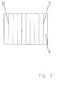
- FIG. 2 shows the filter arrangement 1 according to FIG. 1 in plan view.
- the welded joints 8 are applied linearly along the pleat tips 2 in this embodiment.
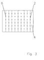
- FIG. 3 shows the filter arrangement 1 according to FIG. 1 in plan view.
- the welded joints 8 are applied punctiform along the pleat tips 2 in this embodiment.
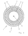
- FIG. 4 shows the filter arrangement 1 according to FIG. 1, wherein the filter arrangement 1 in this embodiment is designed as a cylindrical filter cartridge.
- the supply air side 5 is located on the outer peripheral side and the exhaust side 6 is located on the inner peripheral side of the filter assembly 1.
- the second filter 7 is concentrically arranged on the outer peripheral side of the first filter 4.
- the filter assembly 1 is designed in particular as an engine intake filter of a motor vehicle and in particular of a construction vehicle.
- FIG. 5 shows a filter arrangement 1 according to FIG. 1, wherein the pleat tips 2 and the folding valleys 3 are rounded.
Landscapes
- Chemical & Material Sciences (AREA)
- Chemical Kinetics & Catalysis (AREA)
- Physics & Mathematics (AREA)
- Geometry (AREA)
- Filtering Of Dispersed Particles In Gases (AREA)
- Filtering Materials (AREA)
Applications Claiming Priority (1)
| Application Number | Priority Date | Filing Date | Title |
|---|---|---|---|
| DE102005019262A DE102005019262A1 (de) | 2005-04-26 | 2005-04-26 | Filteranordnung |
Publications (1)
| Publication Number | Publication Date |
|---|---|
| EP1716905A1 true EP1716905A1 (fr) | 2006-11-02 |
Family
ID=36693205
Family Applications (1)
| Application Number | Title | Priority Date | Filing Date |
|---|---|---|---|
| EP06004790A Withdrawn EP1716905A1 (fr) | 2005-04-26 | 2006-03-09 | Dispositif de filtration |
Country Status (4)
| Country | Link |
|---|---|
| US (1) | US20060236664A1 (fr) |
| EP (1) | EP1716905A1 (fr) |
| CN (1) | CN1864806A (fr) |
| DE (2) | DE202005021783U1 (fr) |
Cited By (2)
| Publication number | Priority date | Publication date | Assignee | Title |
|---|---|---|---|---|
| WO2009153216A1 (fr) * | 2008-06-20 | 2009-12-23 | Mahle International Gmbh | Bande filtrante multicouche |
| DE102022129333A1 (de) | 2022-11-07 | 2024-05-08 | Mann+Hummel Gmbh | Filterelement, insbesondere zur Gasfiltration |
Citations (7)
| Publication number | Priority date | Publication date | Assignee | Title |
|---|---|---|---|---|
| FR2214505A1 (en) * | 1973-01-24 | 1974-08-19 | Cfea | Filter element for air, oil or petrol - is mfd. from folded paper, felt or porous plastics, in cylindrical shape |
| US4701197A (en) * | 1986-10-07 | 1987-10-20 | Allied Corp. | Molded panel filter |
| WO1994022557A1 (fr) * | 1993-04-01 | 1994-10-13 | Minnesota Mining And Manufacturing Company | Dispositif filtrant pour la filtration de fluides |
| WO1996033001A1 (fr) * | 1995-04-21 | 1996-10-24 | Donaldson Company, Inc. | Filtre plisse et son procede de fabrication |
| DE19854565A1 (de) * | 1998-11-26 | 2000-05-31 | Mann & Hummel Filter | Mehrlagiges Filterelement |
| US20030230061A1 (en) * | 2002-06-14 | 2003-12-18 | 3M Innovative Properties Company | Collapsible pleated filter element |
| DE202004020174U1 (de) * | 2004-12-23 | 2005-03-17 | Mann & Hummel Gmbh | Luftfilter |
Family Cites Families (13)
| Publication number | Priority date | Publication date | Assignee | Title |
|---|---|---|---|---|
| US4514197A (en) * | 1983-02-15 | 1985-04-30 | Armbruster Joseph M | Filter for air circulator |
| SE8902440L (sv) * | 1989-07-05 | 1991-01-06 | Volvo Ab | Filteranordning, isynnerhet insugningsluftfilter foer foerbraenningsmotorer |
| US5171342A (en) * | 1989-07-31 | 1992-12-15 | Filterwerk Mann & Hummel Gmbh | Filter insert for air filters used in a dust-filled environment |
| DE3925277A1 (de) | 1989-07-31 | 1991-02-07 | Mann & Hummel Filter | Filtereinsatz fuer in staubreichem betrieb eingesetzten luftfilter |
| JP3434117B2 (ja) * | 1996-03-29 | 2003-08-04 | 住友電気工業株式会社 | ディーゼルエンジン用パティキュレートトラップ |
| US7115150B2 (en) * | 2000-09-05 | 2006-10-03 | Donaldson Company, Inc. | Mist filtration arrangement utilizing fine fiber layer in contact with media having a pleated construction and floor filter method |
| JP3803056B2 (ja) * | 2001-11-26 | 2006-08-02 | 本田技研工業株式会社 | フィルタエレメント |
| JP4361263B2 (ja) * | 2002-02-07 | 2009-11-11 | 本田技研工業株式会社 | フィルタエレメント |
| JPWO2003066193A1 (ja) * | 2002-02-07 | 2005-05-26 | 株式会社ブリヂストン | 流体清浄フィルター及びフィルター装置 |
| US6942708B2 (en) * | 2002-04-18 | 2005-09-13 | Rypos, Inc. | Bifilar diesel exhaust filter construction using sintered metal fibers |
| US20040159239A1 (en) * | 2003-02-14 | 2004-08-19 | Nagem Daniel A. | Multi-phase HVAC filtration system |
| US6986428B2 (en) * | 2003-05-14 | 2006-01-17 | 3M Innovative Properties Company | Fluid separation membrane module |
| DE202005019910U1 (de) * | 2005-12-19 | 2007-04-19 | Mann + Hummel Gmbh | Filter |
-
2005
- 2005-04-26 DE DE202005021783U patent/DE202005021783U1/de not_active Expired - Lifetime
- 2005-04-26 DE DE102005019262A patent/DE102005019262A1/de not_active Withdrawn
-
2006
- 2006-03-09 EP EP06004790A patent/EP1716905A1/fr not_active Withdrawn
- 2006-04-25 CN CNA2006100749792A patent/CN1864806A/zh active Pending
- 2006-04-26 US US11/411,509 patent/US20060236664A1/en not_active Abandoned
Patent Citations (7)
| Publication number | Priority date | Publication date | Assignee | Title |
|---|---|---|---|---|
| FR2214505A1 (en) * | 1973-01-24 | 1974-08-19 | Cfea | Filter element for air, oil or petrol - is mfd. from folded paper, felt or porous plastics, in cylindrical shape |
| US4701197A (en) * | 1986-10-07 | 1987-10-20 | Allied Corp. | Molded panel filter |
| WO1994022557A1 (fr) * | 1993-04-01 | 1994-10-13 | Minnesota Mining And Manufacturing Company | Dispositif filtrant pour la filtration de fluides |
| WO1996033001A1 (fr) * | 1995-04-21 | 1996-10-24 | Donaldson Company, Inc. | Filtre plisse et son procede de fabrication |
| DE19854565A1 (de) * | 1998-11-26 | 2000-05-31 | Mann & Hummel Filter | Mehrlagiges Filterelement |
| US20030230061A1 (en) * | 2002-06-14 | 2003-12-18 | 3M Innovative Properties Company | Collapsible pleated filter element |
| DE202004020174U1 (de) * | 2004-12-23 | 2005-03-17 | Mann & Hummel Gmbh | Luftfilter |
Cited By (3)
| Publication number | Priority date | Publication date | Assignee | Title |
|---|---|---|---|---|
| WO2009153216A1 (fr) * | 2008-06-20 | 2009-12-23 | Mahle International Gmbh | Bande filtrante multicouche |
| US8814972B2 (en) | 2008-06-20 | 2014-08-26 | Mahle International Gmbh | Multi-layered filter web |
| DE102022129333A1 (de) | 2022-11-07 | 2024-05-08 | Mann+Hummel Gmbh | Filterelement, insbesondere zur Gasfiltration |
Also Published As
| Publication number | Publication date |
|---|---|
| DE102005019262A1 (de) | 2006-11-09 |
| US20060236664A1 (en) | 2006-10-26 |
| DE202005021783U1 (de) | 2010-02-18 |
| CN1864806A (zh) | 2006-11-22 |
Similar Documents
| Publication | Publication Date | Title |
|---|---|---|
| EP3415213B1 (fr) | Élément filtrant | |
| EP1050331B2 (fr) | Milieu filtrant à deux ou plusieurs couches pour filtration de l'air et élément filtrant à partir de celle-ci | |
| DE112010001186B4 (de) | Filtermedium, Verfahren zur Herstellung eines Filtermediums, und Filterelement | |
| EP2135662B1 (fr) | Elément filtrant compressible avec des capuchons d'extrémité inclinés les uns vers les autres | |
| DE112010005044B4 (de) | Filterelement, Filtereinrichtung und Verfahren zum Herstellen eines Filterelements | |
| EP3043883A1 (fr) | Filtre à air | |
| DE102020113615A1 (de) | Filterelement, Innenraumluftfilter, Filteranordnung und Verwendung eines Filterelements | |
| DE102015013370A1 (de) | Filterelement, insbesondere für ein Kraftfahrzeug sowie Verfahren zum Herstellen eines Filterelements | |
| DE102017123212A1 (de) | Einlasssystemkomponente | |
| DE19922326B4 (de) | Mehrlagiges Filtermedium | |
| DE102014016560A1 (de) | Innenraumfilter und Filteranordnung | |
| EP1716905A1 (fr) | Dispositif de filtration | |
| WO1996036414A1 (fr) | Agencement de filtrage | |
| WO2025083194A1 (fr) | Élément filtrant servant à filtrer un fluide gazeux | |
| DE10249577B4 (de) | Filterelement | |
| DE102007057384A1 (de) | Verfahren zum Herstellen eines Filterelements und Filterelement | |
| DE102018129345A1 (de) | Verfahren zum Herstellen eines Filterelements und Filterelement | |
| EP1867378B1 (fr) | Elément de filtre comprimable | |
| DE102022129489A1 (de) | Filtervorrichtung | |
| DE102010047894A1 (de) | Filterelement und Verfahren zu dessen Herstellung | |
| DE102016011451A1 (de) | Innenraumluftfilter, eine Filteranordnung und ein Verfahren zum Einbauen eines Innenraumluftfilters | |
| EP3536391B1 (fr) | Filtre | |
| EP3630335B1 (fr) | Milieu filtrant, son procédé de fabrication et son utilisation dans un élément filtrant | |
| DE202019104501U1 (de) | Filtereinrichtung für ein Kraftfahrzeug | |
| DE102007050733A1 (de) | Mehrschichtiges Filterelement |
Legal Events
| Date | Code | Title | Description |
|---|---|---|---|
| PUAI | Public reference made under article 153(3) epc to a published international application that has entered the european phase |
Free format text: ORIGINAL CODE: 0009012 |
|
| AK | Designated contracting states |
Kind code of ref document: A1 Designated state(s): AT BE BG CH CY CZ DE DK EE ES FI FR GB GR HU IE IS IT LI LT LU LV MC NL PL PT RO SE SI SK TR |
|
| AX | Request for extension of the european patent |
Extension state: AL BA HR MK YU |
|
| AKX | Designation fees paid |
Designated state(s): AT BE BG CH CY CZ DE DK EE ES FI FR GB GR HU IE IS IT LI LT LU LV MC NL PL PT RO SE SI SK TR |
|
| 17P | Request for examination filed |
Effective date: 20070507 |
|
| 17Q | First examination report despatched |
Effective date: 20070705 |
|
| STAA | Information on the status of an ep patent application or granted ep patent |
Free format text: STATUS: THE APPLICATION HAS BEEN WITHDRAWN |
|
| 18W | Application withdrawn |
Effective date: 20090320 |