EP1716936A1 - Dispositif de séparation de matières lourdes - Google Patents
Dispositif de séparation de matières lourdes Download PDFInfo
- Publication number
- EP1716936A1 EP1716936A1 EP05009117A EP05009117A EP1716936A1 EP 1716936 A1 EP1716936 A1 EP 1716936A1 EP 05009117 A EP05009117 A EP 05009117A EP 05009117 A EP05009117 A EP 05009117A EP 1716936 A1 EP1716936 A1 EP 1716936A1
- Authority
- EP
- European Patent Office
- Prior art keywords
- conveyor
- material components
- flexible
- gas
- heavy
- Prior art date
- Legal status (The legal status is an assumption and is not a legal conclusion. Google has not performed a legal analysis and makes no representation as to the accuracy of the status listed.)
- Withdrawn
Links
- 239000000463 material Substances 0.000 title claims abstract description 125
- 238000011144 upstream manufacturing Methods 0.000 claims abstract description 26
- 239000011343 solid material Substances 0.000 claims abstract description 25
- 238000000034 method Methods 0.000 claims abstract description 7
- 239000007787 solid Substances 0.000 claims description 23
- 238000000151 deposition Methods 0.000 claims description 20
- 229910052751 metal Inorganic materials 0.000 claims description 19
- 239000002184 metal Substances 0.000 claims description 19
- 230000008021 deposition Effects 0.000 claims description 17
- 238000000926 separation method Methods 0.000 claims description 11
- 239000003562 lightweight material Substances 0.000 claims description 6
- 239000000919 ceramic Substances 0.000 claims description 5
- 239000011521 glass Substances 0.000 claims description 5
- 239000000203 mixture Substances 0.000 claims description 5
- 239000004575 stone Substances 0.000 claims description 5
- 230000001105 regulatory effect Effects 0.000 claims description 3
- 239000003570 air Substances 0.000 description 39
- 239000007789 gas Substances 0.000 description 37
- 239000002440 industrial waste Substances 0.000 description 5
- 239000004952 Polyamide Substances 0.000 description 4
- 229920002647 polyamide Polymers 0.000 description 4
- 238000004140 cleaning Methods 0.000 description 3
- 239000010791 domestic waste Substances 0.000 description 3
- 230000005484 gravity Effects 0.000 description 3
- 239000004033 plastic Substances 0.000 description 3
- 229910001220 stainless steel Inorganic materials 0.000 description 3
- 239000010935 stainless steel Substances 0.000 description 3
- 230000032258 transport Effects 0.000 description 3
- XEEYBQQBJWHFJM-UHFFFAOYSA-N Iron Chemical compound [Fe] XEEYBQQBJWHFJM-UHFFFAOYSA-N 0.000 description 2
- 229910000831 Steel Inorganic materials 0.000 description 2
- 238000005452 bending Methods 0.000 description 2
- 239000010959 steel Substances 0.000 description 2
- 241000446313 Lamella Species 0.000 description 1
- 239000000853 adhesive Substances 0.000 description 1
- 230000001070 adhesive effect Effects 0.000 description 1
- 229910052782 aluminium Inorganic materials 0.000 description 1
- XAGFODPZIPBFFR-UHFFFAOYSA-N aluminium Chemical compound [Al] XAGFODPZIPBFFR-UHFFFAOYSA-N 0.000 description 1
- 239000012080 ambient air Substances 0.000 description 1
- 230000000903 blocking effect Effects 0.000 description 1
- -1 boulders Substances 0.000 description 1
- 230000001680 brushing effect Effects 0.000 description 1
- 230000007423 decrease Effects 0.000 description 1
- 230000003247 decreasing effect Effects 0.000 description 1
- 238000001914 filtration Methods 0.000 description 1
- 229910052742 iron Inorganic materials 0.000 description 1
- 239000006148 magnetic separator Substances 0.000 description 1
- 239000007769 metal material Substances 0.000 description 1
- 239000002245 particle Substances 0.000 description 1
- 230000003134 recirculating effect Effects 0.000 description 1
- 238000004064 recycling Methods 0.000 description 1
- 239000011435 rock Substances 0.000 description 1
- 239000008247 solid mixture Substances 0.000 description 1
- 230000007704 transition Effects 0.000 description 1
- 239000002699 waste material Substances 0.000 description 1
- 238000004804 winding Methods 0.000 description 1
- 239000002023 wood Substances 0.000 description 1
Images

Classifications
-
- B—PERFORMING OPERATIONS; TRANSPORTING
- B07—SEPARATING SOLIDS FROM SOLIDS; SORTING
- B07B—SEPARATING SOLIDS FROM SOLIDS BY SIEVING, SCREENING, SIFTING OR BY USING GAS CURRENTS; SEPARATING BY OTHER DRY METHODS APPLICABLE TO BULK MATERIAL, e.g. LOOSE ARTICLES FIT TO BE HANDLED LIKE BULK MATERIAL
- B07B13/00—Grading or sorting solid materials by dry methods, not otherwise provided for; Sorting articles otherwise than by indirectly controlled devices
- B07B13/08—Grading or sorting solid materials by dry methods, not otherwise provided for; Sorting articles otherwise than by indirectly controlled devices according to weight
-
- B—PERFORMING OPERATIONS; TRANSPORTING
- B07—SEPARATING SOLIDS FROM SOLIDS; SORTING
- B07B—SEPARATING SOLIDS FROM SOLIDS BY SIEVING, SCREENING, SIFTING OR BY USING GAS CURRENTS; SEPARATING BY OTHER DRY METHODS APPLICABLE TO BULK MATERIAL, e.g. LOOSE ARTICLES FIT TO BE HANDLED LIKE BULK MATERIAL
- B07B13/00—Grading or sorting solid materials by dry methods, not otherwise provided for; Sorting articles otherwise than by indirectly controlled devices
- B07B13/003—Separation of articles by differences in their geometrical form or by difference in their physical properties, e.g. elasticity, compressibility, hardness
-
- B—PERFORMING OPERATIONS; TRANSPORTING
- B07—SEPARATING SOLIDS FROM SOLIDS; SORTING
- B07B—SEPARATING SOLIDS FROM SOLIDS BY SIEVING, SCREENING, SIFTING OR BY USING GAS CURRENTS; SEPARATING BY OTHER DRY METHODS APPLICABLE TO BULK MATERIAL, e.g. LOOSE ARTICLES FIT TO BE HANDLED LIKE BULK MATERIAL
- B07B4/00—Separating solids from solids by subjecting their mixture to gas currents
- B07B4/08—Separating solids from solids by subjecting their mixture to gas currents while the mixtures are supported by sieves, screens, or like mechanical elements
Definitions
- the present invention relates to a device for the separation of components of high specific gravity from a material flow of a solid mixture consisting of heavy and light material components.
- the invention relates to the separation of heavy particles of a pre-shredded material stream of waste products in a recycling apparatus.
- the object of separating various materials from which a conveyed material flow is composed arises in different fields of application, such as the cleaning of wood material and in particular the separation of heavy materials from pre-shredded industrial waste, industrial waste, household waste, etc.
- Magnetic separators can be used for iron-containing metal materials, but they are of course useless for the sorting of non-metallic heavy materials, such as stones, ceramics, or glass.
- the so-called air separators for classifying and sorting the components of a material flow.
- the material flow is guided into a viewing space and exposed to a conveying air flow.
- a conveying air flow For example (see German Offenlegungsschrift DE 199 45 646 A1 ), the flow of material is introduced into a drum by a conveyor, and as the drum rotates, an airflow directed through the drum carries lower specific gravity material components toward a higher level drum exit, optionally connected to a vacuum chamber, therewith while heavier material components are carried only by the drum to be discharged at a lower drum exit.
- At the transition area from the top Drum output to the outlet channel can also be provided a controllable blocking air flow to further improve the sorting.
- lighter materials may be transported over an airlift between two conveyors produced by a blower while heavy materials fall between the conveyors.
- Such a pure air direction has in particular the disadvantage of the necessary frequent adjustment of the air flow depending on the material composition.
- the required amount of air is very high and it is also, as in the above-mentioned method, the selectivity very limited.
- a combination of the airlift variant with intermediate mechanical conveying by a generally rotating roller to which light matter is carried by an upstream conveyor by means of a downwardly acting fan while heavy materials are to fall in the space between that conveyor and the roller also exhibits the disadvantage of a high amount of air required.
- these designs are particularly sensitive to moisture.
- adhesive heavies entering the drum are disadvantageously conveyed therethrough to the downstream conveyor.
- the material flow is introduced by a conveyor from above into the contact area of two counter-rotating brush rollers.
- Lighter materials should follow the roll rotation, whereas heavy materials should be passed through the contact area between the rolls.
- the heavy material which is sorted out by the brush bristles in the contact area, causes light, in particular relatively small, lightweight material components to be lost to the flow of material.
- a deposition apparatus for depositing heavy material components, in particular stones, ceramics and glass, an inhomogeneous solid material stream comprising heavy and light material components comprising a first conveyor (2) for conveying the solids material stream; a second conveyor (5) provided for conveying the unseparated material components of the solid material stream downstream of the first conveyor (2); flexible means (3) disposed between the downstream end of the first conveyor (2) and the upstream end of the second conveyor (5) and configured to receive the light material components from the first conveyor (2) via the flexible means (3) are conveyed to the second conveyor (5) and the heavy material components leave the solids flow stream upstream of the upstream end of the second conveyor (5).
- the solids material stream may include industrial waste, such as rocks, boulders, steel balls as heavy components, and is transferred to the equipment from upstream.
- the first and the second conveyor may be inclined at different angles to the base.
- the flexible device facing ends can be at the same height.
- the flexible means facing end of the first upstream conveyor will be positioned higher than that of the second downstream conveyor.
- the flexible device has a restoring force, which counteracts the weight of the material components.
- Lightweight material components only marginally bend the flexible device.
- heavy material components may bend the flexible means to exit the solids flow stream upstream of the upstream end of the second conveyor, and in particular to be deposited downwardly into the resulting gap between the two conveyors from the solids flow.
- the flexible device may be at least partially permeable to gas and at least partially permeable to the deposition of the heavy material components for the heavy material components.
- the heavy material components can also be deposited only downstream of the flexible device or exclusively through it.
- the above-mentioned flexible device may comprise, for example, a brush device or a lamella device.
- the term brushing device is to be understood very generally.
- the bristles can be both flexible and rigid, e.g. in the form of metal pins, such as Nirosta metal pins, be formed.
- the bristles can be fixedly positioned or adjustable so that the intermediate bristle spacings can be changed. All of the bristles may be equally spaced from each other, or different bristle spacings may be selected along the brush.
- the brushes may be oriented at different angles to the horizontal. So they can preferably have an angle of less than 45 ° to the horizontal.
- a brush device there are passages between the bristles or bristle groups of the brush device, for example a modified common strip brush as it is also used for the cleaning of conveyor belts.
- the bristles pick up the heavy material components and leave them between them underneath flexible device through where they can be absorbed by a container.
- Such a brush device can be realized in a relatively simple manner as a relatively robust flexible device.
- An alternative embodiment of the flexible device has a lamellar structure.
- the distances between flexible individual slats form the passages for the heavy material components.
- an inclination of the slats or a corresponding angle can be specified and / or adapt to the heavy material components dynamically and / or be continuously controlled during operation.
- the longitudinal direction of the lamellae may be substantially parallel to the material flow direction, i. the conveying direction, or at a certain angle to be oriented.
- the fins may be made of plastic, e.g. Polyamide, or sheet metal, such as aluminum sheet, stainless steel sheet exist.
- the position of the individual slats can be fixed or adjustable.
- the distance between the individual slats can be the same in each case, or different distances between the slats can be selected.
- the separation device may additionally be provided with a gas supply device for supplying gas, such that the flexible device is supported against bending due to the weight of the light and heavy material components.
- the supplied gas may be air of the temperature and density of the ambient air.
- the flexible device can continue to be stabilized by the gas flow relative to the material components bearing on it.
- the gas flow may be regulated to achieve, in combination with the predetermined restoring force of the flexible device, a specific sighting with a good selectivity for a given composition of the solids material stream.
- it may supply air to the gas supply means controllable or controllable according to the weight of the heavy and / or light material components.
- Part of the gas supply may be through the flexible device and partially past the downstream side of the flexible device.
- the velocity of the feed gas, preferably air, above the flexible means is reduced from the velocity below the flexible means.
- the gas blown by the flexible means forms above it an air cushion from which the light components of the solids flow of material can be carried. They drift downstream on the pad and leave the flexible means at the downstream end, e.g. exclusively, by the gas flow can be maintained. Via the gas stream passing the downstream end of the flexible device, the light components are carried on.
- the heavy components initially rely on the flexible device because they are too heavy to lift the air cushion from the surface of the flexible device so as to fall through it at least partially after a short time. Some of the heavy material components may also be deposited after the downstream end of the flexible device and upstream of the downstream conveyor from the solids material stream.
- a very efficient separation of heavy and light solid material components is achieved by the inventive combination of mechanical and gas dynamic sighting.
- the selectivity is higher than the prior art and the required amount of air compared to conventional Windsichtem lower.
- the amount of gas and gas velocity can be optimized in combination with the flexibility of the flexible device chosen and the composition of the solid material stream to be viewed.
- the flexible means may comprise at its downstream end at least two flexible members adapted to independently convey the light material components from the first conveyor to the second conveyor and the heavy material components to direct the solids flow upstream of the upstream end of the second Leave conveyor (5) and thus deposited.
- the flexible elements may be attached to the downstream end or the downstream end may leak into these elements, ie they are cut through corresponding incisions along the longitudinal direction (material flow direction) of the flexible device educated. Thus, some elements may flex under the load of heavy material components while others further convey light material components to the second downstream conveyor.
- the flexible elements may be thin steel sheets, such as stainless steel sheets. You can also be made of plastic, such as polyamide.
- the flexible means may be a metal plate having a plurality of openings when a gas supply means (4) for supplying gas is provided partially through openings of the metal plate and partly past the metal plate on the downstream side.
- a gas supply means (4) for supplying gas is provided partially through openings of the metal plate and partly past the metal plate on the downstream side.
- Heavy material components conveyed by the upstream conveyor strike the metal plate, e.g. a stainless steel plate, and bounce downstream where it is separated from the solid material stream by a gap formed between the downstream end of the metal plate and the upstream end of the downstream conveyor.
- the light material components are transported across the gap by the gas guided past the metal plate.
- the above embodiments of the flexible device may be connected to the first conveyor or the second conveyor or both. Preferably, it may be connected to the first (upstream) conveyor.
- the downstream end of the flexible device may e.g. be held solely by the airflow.
- the separation device may comprise a third conveyor connected upstream of the second conveyor and the light non-separated ones Components of the solid material flow from the flexible device or the air stream, which passes the downstream end of the flexible device and carries the light material components, absorbs and conveys to the second conveyor.
- a third conveyor facilitates the removal of the light components from the flexible device downstream.
- an expansion space for the gas above the flexible device or the metal plate, in particular above the solids material flow can be provided.
- This expansion space can decelerate and trap the flowing gas.
- a suction device for extracting the gas from the expansion space and / or a gas recirculation device for recirculating the gas, optionally after filtering, can be provided from the expansion space to the gas supply device.
- the invention also provides the use of a deposition apparatus for separating heavy material components from an inhomogeneous solids material stream for separating heavy material components from an inhomogeneous solids material stream.
- the flexible device may comprise a brush device.
- the heavy material components are prevented from further transport by the bristles of the brush means, remain on the brush means for a short time, and are then deposited by the brush means.
- the lightweight material components "float" on the air cushion and are transported farther downstream at the downstream end of the flexible device by the gas flow passing therethrough.
- the inventive method allows a sighting with high selectivity.
- the gas quantity, gas velocity and gas flow direction can be controlled or regulated manually or automatically according to the composition of the solids material flow.
- Figure 1 illustrates an example of a deposition apparatus according to the present invention comprising three conveyors and one flexible device.
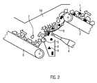
- Figure 2 illustrates an example of a deposition apparatus according to the present invention comprising three conveyors, a blower and a flexible device.
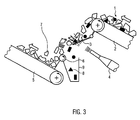
- Figure 3 illustrates another example of a deposition apparatus according to the present invention having a small-hole-provided metal plate as a flexible means.
- an inhomogeneous solid material stream 1 which in particular contains light material components (light-colored) and heavy material components (dark-drawn), is conveyed via a first conveyor 2.
- the conveyor 2 comprises an endless conveyor belt which is moved by a driven rotatable roller as known in the art.
- the conveyor 2 is set up at an angle, and at the upper end a flexible device 3 is connected to the conveyor 2, on which the solids material flow is brought.
- the end of the flexible device 3 is spaced from a second conveyor 5 with a lower end positioned upstream from the downstream end of the first conveyor 2.
- the second downstream conveying device 5 conveys the material components not deposited by the flexible device 3 farther downstream.
- the flexible device 3 is made for example of plastic and has a material-related restoring force.
- the restoring force counteracts the weight force of the material components of the solids material flow which have been transferred to the device.
- Lightweight material components can move across the flexible device without significantly bending the flexible device down.
- Heavy material components bend the flexible device 3 such that they fall down into the space between the first conveyor 2 and the second conveyor 5, and thus from the flow of solid material conveyed by the second conveyor 5, and now substantially only still consists of the light material components are deposited.
- a plurality of flexible elements can be mounted, which can bend independently under the weight of the heavy material components. Likewise, the flexible device 3 downstream leak into several flexible elements that can flex independently under the weight of the heavy material components.
- the heavy deposited material components 8 are received by a suitable collecting container 9.
- a suitable collecting container 9 For better transfer of the light material components to the second conveyor 5 to the further downstream promotion of the light material components, an optional auxiliary conveyor 6 is provided.
- FIG. 2 shows an elaborated example of the separating device according to the invention.
- an inhomogeneous solid material stream 1 with light (light drawn) and heavy (dark drawn) material components is conveyed to the flexible device 3 via a first conveyor 2.
- the conveyor 2 is set up at an angle, and at the upper end a flexible device 3 is connected to the conveyor 2, on which the solids material flow is brought.
- This flexible device 3 comprises a brush device with flexible bristles on the top.
- a brush device with flexible bristles on the top.
- a gas supply device 4 is provided below the flexible device 3, which generates an air flow from below, which extends partially through the flexible device 3.
- the flexible device 3 is partially lifted by the air flow.
- air partially flows past the (material) downstream side on the flexible device 3 without decreasing the speed (in FIG. 2, the solid individual lines above the air supply device designate the air leaving the air supply device and the downstream side of the flexible device 3 whereas the dashed lines indicate the air passing through the flexible device).
- the gas supply means may preferably supply air at an air flow rate of between 7,000 and 15,000 cubic meters per hour, more preferably between 8,000 and 12,000 cubic meters per hour, to provide, in combination with the elastic means, a flow rate
- a polyamide flat brush such as that used to clean conveyor belts, involves achieving satisfactory selectivity for a typical solid material stream from light industrial waste or household waste. For a typical solid material stream from light industrial waste or household waste, it may be advantageous to control or regulate the air velocity to between 15 and 30 m / s at the entrance to the flexible device.
- the velocity of the air blown through the flexible means 3 decreases significantly, creating an air swirl characterized by air swirl on the surface of the flexible means 3.
- Lighter material components of the spent on the flexible device 3 solid material flow 1 are lifted by the resulting air cushion from the surface of the flexible device 3 and transported away over this.
- the end of the flexible means 3 is spaced from a second conveyor 5 and a portion of the air flow supplied by the gas supply means transports the light material components of the solid material stream to an auxiliary conveyor 6 connected to the conveyor 5 and together with the downstream end of the flexible Device 3 defines the open space through which a portion of the supplied air flows to transport the light components downstream of the flexible device 3 (material).
- the conveyor belt of the auxiliary conveyor 6 is oriented perpendicular to that of the conveyor 5. Other angles of the conveyor belts to each other are possible. Also, the auxiliary conveyor 6 is an optional component of the entire system. The light material components 7 are eventually conveyed further downstream by the second conveyor 5.
- the heavy material components 8, ie the components of the inhomogeneous solid material stream 1 with high specific gravity, are not lifted by the air cushion formed on the surface of the flexible device 3, but remain briefly on or between the brush bristles, and then through the openings of the insects of the insects Clubs down to get into a corresponding receptacle 9.
- the flexible device 3 does not necessarily comprise a brush device. It is essential that it lets in gas fed from below and lets heavy material components down. A lamellar device can replace the brush device. Furthermore, the bristles may be formed in the form of non-flexible pins or rods.
- the expansion chamber has a gas outlet, which can optionally be connected to the gas supply device again.
- the extent of the flexible device 3 from the downstream end of the conveyor 2 towards the upstream end of the conveyor 5 can be chosen differently.
- a distance between the downstream end of the flexible device 3 and the upstream end of the conveyor 5 and the auxiliary conveyor 6 may be provided.
- the heavy material components can be deposited down through both the flexible device 3 and in the gap formed by said distance.
- the air passing the downstream end of the flexible device 3 carries the light material components across the gap.
- the device 3 between the conveyors 2 and 5 or 6 is represented by a metal plate.
- This has holes through which the air supplied from below through the air supply 4 partially passes.
- Heavy material components, which are conveyed from the conveyor 2 to the device 3 encounter these and jump in the downstream direction, ie in the direction of the gap, from the metal plate 3 from. While the light material components 7 are carried to the conveyor 6 through the gap between the conveyor 6 and the downstream end of the metal plate 3 through the air partially passed at the downstream end of the metal plate 3, the heavy material components 8 fall down into the designated receptacle.
- the heavy material components are not at least partially separated by means 3, but rather exclusively downstream of the same from the material flow.
Landscapes
- Engineering & Computer Science (AREA)
- Mechanical Engineering (AREA)
- Combined Means For Separation Of Solids (AREA)
Priority Applications (3)
| Application Number | Priority Date | Filing Date | Title |
|---|---|---|---|
| EP05009117A EP1716936A1 (fr) | 2005-04-26 | 2005-04-26 | Dispositif de séparation de matières lourdes |
| US11/912,564 US7819256B2 (en) | 2005-04-26 | 2006-04-26 | Heavy material separator |
| PCT/EP2006/003877 WO2006114302A1 (fr) | 2005-04-26 | 2006-04-26 | Separateur de matieres lourdes |
Applications Claiming Priority (1)
| Application Number | Priority Date | Filing Date | Title |
|---|---|---|---|
| EP05009117A EP1716936A1 (fr) | 2005-04-26 | 2005-04-26 | Dispositif de séparation de matières lourdes |
Publications (1)
| Publication Number | Publication Date |
|---|---|
| EP1716936A1 true EP1716936A1 (fr) | 2006-11-02 |
Family
ID=34978925
Family Applications (1)
| Application Number | Title | Priority Date | Filing Date |
|---|---|---|---|
| EP05009117A Withdrawn EP1716936A1 (fr) | 2005-04-26 | 2005-04-26 | Dispositif de séparation de matières lourdes |
Country Status (3)
| Country | Link |
|---|---|
| US (1) | US7819256B2 (fr) |
| EP (1) | EP1716936A1 (fr) |
| WO (1) | WO2006114302A1 (fr) |
Cited By (1)
| Publication number | Priority date | Publication date | Assignee | Title |
|---|---|---|---|---|
| EP2177461A1 (fr) * | 2008-10-20 | 2010-04-21 | Lindner, Manuel | Dispositif de répartition de matériau |
Families Citing this family (3)
| Publication number | Priority date | Publication date | Assignee | Title |
|---|---|---|---|---|
| US8517177B2 (en) * | 2009-08-05 | 2013-08-27 | Barry D. Graham | Systems and methods for recovering materials from soil |
| CN102873031B (zh) * | 2012-10-10 | 2015-08-26 | 北京中科通用能源环保有限责任公司 | 垃圾分选系统及方法 |
| CN109351692B (zh) * | 2018-10-25 | 2021-04-20 | 明池玻璃股份有限公司 | 一种玻璃精确甄别处理设备及玻璃精确甄别处理工艺 |
Citations (8)
| Publication number | Priority date | Publication date | Assignee | Title |
|---|---|---|---|---|
| GB1184616A (en) | 1967-11-28 | 1970-03-18 | Andrew Gray Bonella | Potato Harvester. |
| DE8715942U1 (de) | 1987-12-02 | 1988-01-28 | Rudnick + Enners Maschinen- und Anlagenbau GmbH, 57642 Alpenrod | Schwergutabscheider |
| GB2193449A (en) | 1986-08-13 | 1988-02-10 | Uralsky Politekhn Inst | Air gravity classifier for loose materials |
| DE4031584A1 (de) | 1990-10-05 | 1992-04-09 | Lindemann Maschfab Gmbh | Vorrichtung zum sortieren von feststoffgemischen |
| EP0482566A2 (fr) | 1990-10-24 | 1992-04-29 | IPERFIN S.p.A. | Crible pour séparer des matériaux de poids différents |
| DE29606223U1 (de) | 1996-01-18 | 1996-07-11 | Kraus, Harri, 38446 Wolfsburg | Sortier- und Siebanlage für Stoffgemische |
| WO2002038291A1 (fr) | 2000-11-07 | 2002-05-16 | Vasara, Jussi | Procede et dispositif destines a separer des impuretes a partir de matieres grossieres ou pulverulentes |
| DE20217037U1 (de) | 2002-08-01 | 2003-04-03 | Schulte + Strehlau GmbH Maschinen- und Anlagenbau, 49762 Lathen | Vorrichtung zum Trennen von schweren und leichten Anteilen eines Massenstroms |
Family Cites Families (4)
| Publication number | Priority date | Publication date | Assignee | Title |
|---|---|---|---|---|
| US1184616A (en) * | 1915-03-24 | 1916-05-23 | Carl E Brown | Oil-burner. |
| US3334739A (en) | 1964-04-22 | 1967-08-08 | Ransomes Sims & Jefferies | Dressing shoes for grain threshing mechanisms |
| US5641055A (en) * | 1995-07-06 | 1997-06-24 | Carruthers Equipment Co. | Conveyor belt |
| US5938373A (en) * | 1995-07-20 | 1999-08-17 | Scudder; Erik D. | Apparatus for padding a trench including crusher for pulverizing excavated material into grades of material |
-
2005
- 2005-04-26 EP EP05009117A patent/EP1716936A1/fr not_active Withdrawn
-
2006
- 2006-04-26 US US11/912,564 patent/US7819256B2/en not_active Expired - Fee Related
- 2006-04-26 WO PCT/EP2006/003877 patent/WO2006114302A1/fr not_active Ceased
Patent Citations (8)
| Publication number | Priority date | Publication date | Assignee | Title |
|---|---|---|---|---|
| GB1184616A (en) | 1967-11-28 | 1970-03-18 | Andrew Gray Bonella | Potato Harvester. |
| GB2193449A (en) | 1986-08-13 | 1988-02-10 | Uralsky Politekhn Inst | Air gravity classifier for loose materials |
| DE8715942U1 (de) | 1987-12-02 | 1988-01-28 | Rudnick + Enners Maschinen- und Anlagenbau GmbH, 57642 Alpenrod | Schwergutabscheider |
| DE4031584A1 (de) | 1990-10-05 | 1992-04-09 | Lindemann Maschfab Gmbh | Vorrichtung zum sortieren von feststoffgemischen |
| EP0482566A2 (fr) | 1990-10-24 | 1992-04-29 | IPERFIN S.p.A. | Crible pour séparer des matériaux de poids différents |
| DE29606223U1 (de) | 1996-01-18 | 1996-07-11 | Kraus, Harri, 38446 Wolfsburg | Sortier- und Siebanlage für Stoffgemische |
| WO2002038291A1 (fr) | 2000-11-07 | 2002-05-16 | Vasara, Jussi | Procede et dispositif destines a separer des impuretes a partir de matieres grossieres ou pulverulentes |
| DE20217037U1 (de) | 2002-08-01 | 2003-04-03 | Schulte + Strehlau GmbH Maschinen- und Anlagenbau, 49762 Lathen | Vorrichtung zum Trennen von schweren und leichten Anteilen eines Massenstroms |
Cited By (2)
| Publication number | Priority date | Publication date | Assignee | Title |
|---|---|---|---|---|
| EP2177461A1 (fr) * | 2008-10-20 | 2010-04-21 | Lindner, Manuel | Dispositif de répartition de matériau |
| WO2010046059A1 (fr) * | 2008-10-20 | 2010-04-29 | Lindner, Manuel | Dispositif répartiteur de matière |
Also Published As
| Publication number | Publication date |
|---|---|
| US7819256B2 (en) | 2010-10-26 |
| WO2006114302A1 (fr) | 2006-11-02 |
| US20080290001A1 (en) | 2008-11-27 |
Similar Documents
| Publication | Publication Date | Title |
|---|---|---|
| EP1027837B1 (fr) | Dispositif pour la formation d'une mono-couche à partir d'une épaisse couche de matière continue | |
| DE102012016057A1 (de) | Trennvorrichtung für eine Kartoffelerntemaschine oder eine Aufbereitungsmaschine | |
| EP0636322B1 (fr) | Dispositif de transport pour la formation d'une couche uniforme | |
| DE10141375C1 (de) | Vorrichtung zum Trennen von Sendungen in Dickenklassen | |
| EP2665565A1 (fr) | Procédé et dispositif de criblage des impuretés contenues dans un flux pneumatique de fibres | |
| DE19501263C2 (de) | Verfahren und Vorrichtung zur Sichtung eines Materialien-Gemisches | |
| WO2006114302A1 (fr) | Separateur de matieres lourdes | |
| EP1579774A1 (fr) | Procédé et dispositif pour l'élimination de corps étrangers dans un courant de tabac | |
| DE102017215374B4 (de) | Fördervorrichtung | |
| DE102020005687B4 (de) | Windstreuvorrichtung | |
| EP2800619B1 (fr) | Séparateur du type cyclone, en particulier pour la gestion des déchets | |
| DE102007049780A1 (de) | Verfahren und Vorrichtung zum kontrollierten Übergeben von Stückgütern | |
| DE3704050C2 (de) | Blattförderer | |
| DE4413288C2 (de) | Vorrichtung zur Selektion von Bauschutt | |
| EP4076775B1 (fr) | Dispositif et procédé pour le triage d'un mélange de matières | |
| DE102020005686B4 (de) | Windstreuvorrichtung | |
| DE102008058998B4 (de) | Verfahren zur Sichtung bzw. Klassifizierung von geschnittenem, pflanzlichen Schüttgut, insbesondere Tabak, sowie Vorrichtung zur Durchführung des Verfahrens | |
| DE102019008916A1 (de) | Vorrichtung und Verfahren zur Sichtung eines Materialien-Gemisches | |
| DE20217037U1 (de) | Vorrichtung zum Trennen von schweren und leichten Anteilen eines Massenstroms | |
| DE4325838A1 (de) | Einrichtung zum Ausscheiden von Fremdkörpern aus einem Tabakstrom | |
| DE202019005280U1 (de) | Vorrichtung zur Sichtung eines Materialien-Gemisches | |
| DE102016222201B4 (de) | Fördervorrichtung | |
| WO2005122804A1 (fr) | Separation de corps etrangers presents dans un flux de tabac | |
| DE102017200260B4 (de) | Fördervorrichtung | |
| EP1775031A2 (fr) | Dispositif de séparation de déchets, en particulier séparateur à air |
Legal Events
| Date | Code | Title | Description |
|---|---|---|---|
| PUAI | Public reference made under article 153(3) epc to a published international application that has entered the european phase |
Free format text: ORIGINAL CODE: 0009012 |
|
| AK | Designated contracting states |
Kind code of ref document: A1 Designated state(s): AT BE BG CH CY CZ DE DK EE ES FI FR GB GR HU IE IS IT LI LT LU MC NL PL PT RO SE SI SK TR |
|
| AX | Request for extension of the european patent |
Extension state: AL BA HR LV MK YU |
|
| 17P | Request for examination filed |
Effective date: 20070326 |
|
| AKX | Designation fees paid |
Designated state(s): AT BE BG CH CY CZ DE DK EE ES FI FR GB GR HU IE IS IT LI LT LU MC NL PL PT RO SE SI SK TR |
|
| 17Q | First examination report despatched |
Effective date: 20090506 |
|
| STAA | Information on the status of an ep patent application or granted ep patent |
Free format text: STATUS: THE APPLICATION IS DEEMED TO BE WITHDRAWN |
|
| 18D | Application deemed to be withdrawn |
Effective date: 20151103 |