EP1716981A2 - Werkzeugträgereinsatz für Lagerbehälter - Google Patents
Werkzeugträgereinsatz für Lagerbehälter Download PDFInfo
- Publication number
- EP1716981A2 EP1716981A2 EP06112911A EP06112911A EP1716981A2 EP 1716981 A2 EP1716981 A2 EP 1716981A2 EP 06112911 A EP06112911 A EP 06112911A EP 06112911 A EP06112911 A EP 06112911A EP 1716981 A2 EP1716981 A2 EP 1716981A2
- Authority
- EP
- European Patent Office
- Prior art keywords
- base portion
- sleeve
- tool
- tool holder
- insert
- Prior art date
- Legal status (The legal status is an assumption and is not a legal conclusion. Google has not performed a legal analysis and makes no representation as to the accuracy of the status listed.)
- Withdrawn
Links
Images



Classifications
-
- B—PERFORMING OPERATIONS; TRANSPORTING
- B25—HAND TOOLS; PORTABLE POWER-DRIVEN TOOLS; MANIPULATORS
- B25H—WORKSHOP EQUIPMENT, e.g. FOR MARKING-OUT WORK; STORAGE MEANS FOR WORKSHOPS
- B25H3/00—Storage means or arrangements for workshops facilitating access to, or handling of, work tools or instruments
- B25H3/003—Holders for drill bits or the like
Definitions
- the present invention relates to tool containers and, more specifically, to inserts which are adapted to be retained within the containers.
- Tool users whether casual or professional, desire to maintain their tools in some type of organized fashion that provides for easy access to the tools.
- Several types of tool containers serve such a function.
- a tool holder insert is provided that is selectively located in a storage container for storing a tool holder therein.
- the tool holder insert includes a base portion and a sleeve.
- the base portion has a first end and a second end.
- the first end includes an interlock feature adapted to be non-rotatably coupled to a storage container.
- the sleeve is rotatably coupled to the base between the first and second ends.
- Figures 1 and 2 show a tool container 10 having two housing members 12, 14 which are pivotally secured to one another by a hinge 16.
- the housing members 12, 14 include peripheral walls 18, 20 defining lateral walls 22, 24; 26, 28 and longitudinal walls 30, 32; 34, 36.
- the longitudinal walls 30, 32; 34, 36 include a plurality of dovetail tenons 38 and recesses 40 that define interlock features. It should be understood that other interlock features can also be used.
- the structure of the exemplary tool container 10 is described in more detail in commonly assigned US Patent No. 6,755,302 , herein incorporated by reference.
- the insert 42 of the present invention is shown in engagement with the dovetail tenons 38.
- FIGS 3-8 depict an exemplary preferred embodiment of an insert 42 supporting a bit holder 44 according to the teachings of the present invention, shown merely for purposes of illustration.
- One skilled in the art will readily recognize, from the following discussion and accompanying drawings, a variety of specialized inserts can advantageously employ the principles of the present invention.
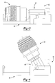
- FIGs 3, 4 and 8 show the insert 42 and a bit holder 44 in greater detail.
- the insert 42 includes a base 46 and a sleeve 48.
- the insert 42 provides storage for the bit holder 44.
- the sleeve 48 retains the bit holder 44 and is pivotally supported by the base 46 providing a storage position (shown in Figure 3) and an access position (shown in Figure 4).
- the bit holder 44 includes a body 50 having a hex shank 52 extending therefrom.
- a hex-shaped bore 54 is formed in the body 50, with the bore 54 opening axially outwardly toward the front of the bit holder 44.
- the structure of the bit holder 44 is described in more detail in commonly assigned U.S. Patent Application No.
- Figures 3-6 show the base 46 of the insert 42 in greater detail.
- the base 46 includes a first end 56 and a second end 58.
- the first end 56 is removably coupled to the tool container 10 at a rear wall 60.
- the rear wall 60 includes a rear surface 62 having a plurality of tenons 64 and recesses 66 to mate, respectively, with the dovetail tenons 38 and recesses 40 (shown in Fig. 2) provided on the longitudinal walls 30, 32, 34, 36 of the tool container 10.
- the tenons 64 have angled walls 68, 70. Also, the tenons 64 are larger at the top 72 and smaller at the bottom 74 to provide an overall trapezoidal shape.
- the recesses 66 are defined by the walls 68, 70 of the tenons 64 and include a rear wall 76.
- the recesses 66 are larger at the bottom 78 and smaller at the top 80 to provide an overall trapezoidal shape.
- the tool retaining insert 42 is positioned inside of the housing members 12, 14 so that a friction fit is maintained between the housing members 12, 14 and the insert 42. The friction is such that the tool retaining insert 42 is substantially fixedly maintained within the tool container 10.
- a front wall 82 is located between the rear wall 60 and the second end 58 of the base 46.
- the front wall 82 includes a V-shaped recessed cradle 84 for receiving the hexagonal shaped outer surface 86 of the sleeve 48.
- a pair of sidewalls 88, 90 extend from the base 46 at the first end 56 and connect the front 82 and rear 60 walls.
- the sidewalls 88, 90 are generally perpendicular to the rear wall 60 and include a series of pivot receptors 92, 94 for engagement with the sleeve 48.
- the pivot receptors 92, 94 extend generally inwardly from the sidewalls 88, 90 and generally below the upper sidewall surface 96.
- the pivot receptors 92, 94 are generally identical, therefore only one pivot receptor 92 will be described in detail.
- the pivot receptor 92 includes an aperture 98 passing through the sidewall 88 and a protrusion 100 partially surrounding the aperture 98.
- a first portion 102 of the protrusion 100 is located a distance slightly less than the diameter of one of the arms 104 of the sleeve 48, providing a snap fit for the arm 104 between the upper sidewall surface 96 and the first portion 102.
- a second portion 106 of the protrusion 100 has a generally arcuate shape and is sized similar to the arm 104, having a slightly larger diameter than that of the arm 104, allowing the arm 104 to freely rotate therein.
- a chamber 108 is defined by the series of sidewalls 88, 90 and the front 82 and rear 60 walls and generally houses a portion of the sleeve 48.
- the chamber 108 further includes an aperture 110 extending through the base 46, allowing the sleeve 48 to pass therethrough from the lower surface 112 to the chamber 108.
- the aperture 110 generally extends between the sidewalls 88, 90, rear wall 60 and front wall 82.
- a side portion 114 of the base 46 extends outwardly from each of the sidewalls 88, 90.
- the side portion 114 generally extends the length of the sidewalls 88, 90 and connects with the rear wall 60.
- An upper wall portion 116 extends from the rear wall 60 and has a semi-hexagonal shape.
- An elongated portion extends from the front wall 82 in a direction generally opposite the recess 108 and generally defines the second end 58.
- the second end 58 is generally rectangular and includes an arcuate recess 120 for housing the bit holder 44.
- the arcuate recess 120 has a rib 122 disposed therein to support a portion of the body 50 of the bit holder 44.
- the base 46 further includes a finger 124 located at the second end 58. The finger 124 extends generally upward from the lower surface 112 of the base 46 to a height generally equal to the height of the bore 54 of the bit holder 44 when in a storage position.
- the finger 124 includes a top portion 126 extending toward the first end 56 and partially into the bore 54 of the bit holder 44, providing engagement between the base 46 and bit holder 44 retained in the sleeve 48 so that the bit holder 44 cannot become inadvertently dislodged from the sleeve 48.
- the sleeve 48 is shown in greater detail in Figures 3-4 and 7.
- the sleeve 48 includes a body 134 having a first end 128, a second end 130 and a recess 132 extending partially into the body 134 of the sleeve 48 from the first end 128.
- the second end 130 includes a wall 136 defining a stop for the recess 132.
- the hex shank 52 of the bit holder 44 is housed in the sleeve 48.
- the sleeve 48 has a generally hexagonal outer surface 86 and a generally hexagonal inner recess 132, thereby accommodating the hex shank 52 of the bit holder 44.
- the sleeve 48 may be inserted into the chamber 108 through the aperture 110 through the lower surface 112.
- a series of generally cylindrical arms 104 extend from a medial portion of the sleeve 48 and are able to be snapped into the pivot receptors 92, 94 in the sidewalls 88, 90 after the sleeve 48 is inserted through the aperture 110 in the chamber 108 at the first end 56. Once the arms 104 are snapped into the pivot receptors 92, 94, the sleeve 48 is pivotally supported by the base 46.
- the upper sidewall surface 96 prevents the sleeve 48 from being removed from the top.
- the V-shaped cradle 84 of the base 46 allows the first end 56 of the sleeve 48 to rest thereon, thereby supporting the sleeve 48 in a storage position.
- a series of projections 138, 140 extend outwardly from the body 134 of the sleeve 48. These projections 138, 140 serve as stops, allowing the sleeve 48 to be indexed between a horizontal position (shown in Figure 3) with respect to the base 46 and an angularly upright position (shown in Figure 4). This is achieved through the projections 138, 140 extending from the sleeve 48 a distance greater than the distance defined between the upper sidewall surfaces 96, causing an interference fit.
- a first series of projections 138 are disposed between the arms 104 and the first end 56 and are slightly above the arms 104 when in a storage position, providing indexing for an angularly upright position.
- a second series of projections 140 are located between the arms 104 and the second end 58 and above the first series of stops 138 when the sleeve 48 is in a storage position.
Landscapes
- Engineering & Computer Science (AREA)
- Mechanical Engineering (AREA)
- Packaging Of Annular Or Rod-Shaped Articles, Wearing Apparel, Cassettes, Or The Like (AREA)
- Purses, Travelling Bags, Baskets, Or Suitcases (AREA)
- Workshop Equipment, Work Benches, Supports, Or Storage Means (AREA)
- Details Of Rigid Or Semi-Rigid Containers (AREA)
Applications Claiming Priority (1)
| Application Number | Priority Date | Filing Date | Title |
|---|---|---|---|
| US11/113,907 US7328796B2 (en) | 2005-04-25 | 2005-04-25 | Tool holder insert for storage container |
Publications (2)
| Publication Number | Publication Date |
|---|---|
| EP1716981A2 true EP1716981A2 (de) | 2006-11-02 |
| EP1716981A3 EP1716981A3 (de) | 2007-01-31 |
Family
ID=36685576
Family Applications (1)
| Application Number | Title | Priority Date | Filing Date |
|---|---|---|---|
| EP06112911A Withdrawn EP1716981A3 (de) | 2005-04-25 | 2006-04-21 | Werkzeugträgereinsatz für Lagerbehälter |
Country Status (2)
| Country | Link |
|---|---|
| US (1) | US7328796B2 (de) |
| EP (1) | EP1716981A3 (de) |
Cited By (1)
| Publication number | Priority date | Publication date | Assignee | Title |
|---|---|---|---|---|
| CN103372858A (zh) * | 2012-04-23 | 2013-10-30 | 艾温工业工具公司 | 孔锯工具箱 |
Families Citing this family (30)
| Publication number | Priority date | Publication date | Assignee | Title |
|---|---|---|---|---|
| US7780016B1 (en) * | 2005-07-08 | 2010-08-24 | Jore Corporation | Tool holder |
| US20100155275A1 (en) * | 2007-05-25 | 2010-06-24 | Meadwestvaco Corporation | Packages for holding compact discs |
| US8376665B2 (en) * | 2007-08-20 | 2013-02-19 | Milwaukee Electric Tool Corporation | Cutting tool, cutting tool kit, and method of operating the same |
| US7854321B2 (en) | 2008-07-01 | 2010-12-21 | The Stanley Works Israel Ltd. | Rolling container assembly |
| US8342841B2 (en) * | 2008-07-30 | 2013-01-01 | Zimmer Dental, Inc. | Procedure specific storage block for holding implant containers and surgical tools |
| WO2010034150A1 (en) * | 2008-09-24 | 2010-04-01 | Black & Decker Inc. | Insert for tool container |
| USD608094S1 (en) | 2008-12-11 | 2010-01-19 | Black & Decker Inc. | Case for socket wrench accessories |
| US7806264B1 (en) * | 2009-04-30 | 2010-10-05 | Jin-Tsai Lai | Toolbox having positioning structure |
| US9089955B2 (en) | 2009-06-09 | 2015-07-28 | Baseline Redefined, Llc | Locking mechanism and tool device |
| US8430003B1 (en) | 2009-06-09 | 2013-04-30 | Robyn Marie Johnson | High density tool and locking system |
| USD645663S1 (en) * | 2011-01-26 | 2011-09-27 | Jpj Investment Holding Corp. | Tool case |
| USD795874S1 (en) * | 2011-11-30 | 2017-08-29 | Western Digital Technologies, Inc. | Ruggedized enclosure for a data storage device |
| USD691371S1 (en) * | 2012-10-02 | 2013-10-15 | Goood Year Hardware Co., Ltd. | Toolbox |
| USD729520S1 (en) | 2013-07-02 | 2015-05-19 | Hilti Aktiengesellschaft | Box for bits and/or tools |
| US9186789B2 (en) * | 2013-12-25 | 2015-11-17 | Tzu-Chien Wang | Operating rod assembly for a toolbox |
| US9723902B2 (en) * | 2015-02-14 | 2017-08-08 | Boban Jose | Collapsible suitcase, and a method for its use |
| US9907378B2 (en) | 2015-02-14 | 2018-03-06 | Boban Jose | Retractable luggage extension handle with a ring-shaped grip |
| US9918536B2 (en) | 2015-02-14 | 2018-03-20 | Boban Jose | Luggage extension handle having a ring-shaped grip |
| US9918535B2 (en) | 2015-02-14 | 2018-03-20 | Boban Jose | Luggage extension handle having a pocket |
| US9845915B2 (en) | 2015-09-02 | 2017-12-19 | Boban Jose | Collapsible stand attached to a baggage item and a method for its use |
| US9999283B2 (en) | 2015-12-31 | 2018-06-19 | Boban Jose | Collapsible luggage and a method for its use |
| US9833047B1 (en) | 2016-06-01 | 2017-12-05 | Boban Jose | Locking slider assembly and a method for its manufacture |
| US10085526B2 (en) | 2016-06-01 | 2018-10-02 | Boban Jose | Locking slider assembly and a method for its manufacture |
| US9743721B1 (en) | 2016-06-01 | 2017-08-29 | Boban Jose | Locking slider assembly and a method for its manufacture |
| US9767673B1 (en) | 2016-06-07 | 2017-09-19 | Paul Clip | System and method for detecting that an open bag is being carried |
| US11912477B2 (en) | 2022-06-08 | 2024-02-27 | Yeti Coolers, Llc | Container with handle and latching system |
| USD1036116S1 (en) | 2022-06-08 | 2024-07-23 | Yeti Coolers, Llc | Container |
| USD1024557S1 (en) | 2022-06-08 | 2024-04-30 | Yeti Coolers, Llc | Container |
| USD1063376S1 (en) | 2022-06-08 | 2025-02-25 | Yeti Coolers, Llc | Container |
| USD1036119S1 (en) | 2022-11-30 | 2024-07-23 | Yeti Coolers, Llc | Container |
Citations (2)
| Publication number | Priority date | Publication date | Assignee | Title |
|---|---|---|---|---|
| US20030230862A1 (en) | 2002-06-18 | 2003-12-18 | Peters Michael P. | Bit holder |
| US6755302B1 (en) | 1998-08-14 | 2004-06-29 | Black & Decker Inc. | Tool container |
Family Cites Families (18)
| Publication number | Priority date | Publication date | Assignee | Title |
|---|---|---|---|---|
| DE1893098U (de) | 1963-01-30 | 1964-05-14 | Elisabeth Hielscher | Magnetische aufhaengevorrichtung fuer stielgeraete. |
| US3578153A (en) * | 1969-08-07 | 1971-05-11 | John L Olson | Drill holder device |
| US3870149A (en) * | 1973-04-23 | 1975-03-11 | Huot Manufacturing Company | Drill holding case |
| DE8512275U1 (de) | 1985-04-25 | 1985-06-05 | Gisbert Brinkschulte Gmbh & Co Kg, 2800 Bremen | Kassette zur Aufbewahrung länglicher Gegenstände |
| US5570784A (en) | 1992-12-24 | 1996-11-05 | Allied Wholesale, Inc. | Tool organizer and deployment apparatus |
| DK0686462T3 (da) | 1994-06-06 | 1997-12-22 | Straumann Inst Ag | Kassette til instrumenter og apparater, især til tandmedicin. |
| US5645177A (en) | 1996-05-06 | 1997-07-08 | Lin; Da-Sen | Tool rack |
| DE19620566B4 (de) * | 1996-05-22 | 2007-05-31 | Wera-Werk Hermann Werner Gmbh & Co. | Aufbewahrungsvorrichtung für Schraubendreherbits oder dergleichen und zugehörigem Futter |
| US6405864B1 (en) | 1998-08-14 | 2002-06-18 | Black & Decker Inc. | Tool container |
| US6047827A (en) * | 1999-03-22 | 2000-04-11 | Huang; Hung Chen | Assembling bit receiving device |
| US6119859A (en) | 1999-10-27 | 2000-09-19 | Wen; Hsiu Chu | Adjustable tool bit storage structure for a tool box |
| DE19955409B4 (de) | 1999-11-18 | 2006-05-11 | Kao, Jui-Chien, Tali | Gestell zum Aufhängen von hülsenartigen Elementen mit einem Aufnahmeraum |
| US7237673B2 (en) * | 2001-04-23 | 2007-07-03 | Black & Decker Inc. | Container for tool bits |
| US20030070999A1 (en) | 2001-10-15 | 2003-04-17 | Jui-Chien Kao | Tool suspension rack |
| US20030141211A1 (en) | 2002-01-31 | 2003-07-31 | Tsai Chang Chi | Structure of a tool-displaying device |
| US6854607B2 (en) | 2003-03-28 | 2005-02-15 | Hui Lin Tong | Adjustable tool support and display device |
| US6953114B2 (en) * | 2003-04-09 | 2005-10-11 | Mei-Chen Wang | Toolbox |
| US20060201835A1 (en) * | 2005-03-09 | 2006-09-14 | Test Rite Products Corporation | Tool organizer |
-
2005
- 2005-04-25 US US11/113,907 patent/US7328796B2/en not_active Expired - Lifetime
-
2006
- 2006-04-21 EP EP06112911A patent/EP1716981A3/de not_active Withdrawn
Patent Citations (2)
| Publication number | Priority date | Publication date | Assignee | Title |
|---|---|---|---|---|
| US6755302B1 (en) | 1998-08-14 | 2004-06-29 | Black & Decker Inc. | Tool container |
| US20030230862A1 (en) | 2002-06-18 | 2003-12-18 | Peters Michael P. | Bit holder |
Cited By (2)
| Publication number | Priority date | Publication date | Assignee | Title |
|---|---|---|---|---|
| CN103372858A (zh) * | 2012-04-23 | 2013-10-30 | 艾温工业工具公司 | 孔锯工具箱 |
| CN103372858B (zh) * | 2012-04-23 | 2017-03-01 | 艾温工业工具公司 | 孔锯工具箱 |
Also Published As
| Publication number | Publication date |
|---|---|
| US7328796B2 (en) | 2008-02-12 |
| EP1716981A3 (de) | 2007-01-31 |
| US20060243617A1 (en) | 2006-11-02 |
Similar Documents
| Publication | Publication Date | Title |
|---|---|---|
| US7328796B2 (en) | Tool holder insert for storage container | |
| US11192235B2 (en) | Tool bit case with modular components | |
| CN106687256B (zh) | 用于分类箱的插入件 | |
| US7600640B2 (en) | Multi-configured tool bit box | |
| US7032483B2 (en) | Toolbox screwdriver | |
| AU711258B2 (en) | Insulated container | |
| EP1366866B1 (de) | Doppelstapel Werkzeugregal | |
| US4932294A (en) | DIY electric hand tool having a chamber for accommodating tool heads not in use | |
| CN219132258U (zh) | 工具箱体 | |
| WO2001010745A1 (en) | Tool item container | |
| US8196742B1 (en) | Tool bit toolbox | |
| US20200298378A1 (en) | Ratchet, Ratchet Accessory, and Kit Including the Same | |
| US20230294270A1 (en) | Tool box | |
| US5881935A (en) | Container holding device | |
| US20060201835A1 (en) | Tool organizer | |
| US9186789B2 (en) | Operating rod assembly for a toolbox | |
| US20050126944A1 (en) | Packaging, storage and display apparatus and system | |
| KR200286603Y1 (ko) | 걸이구 | |
| WO2010034150A1 (en) | Insert for tool container | |
| HK1114753A1 (zh) | 一種儲放工具的裝置 | |
| HK1114753B (en) | Tool storage device |
Legal Events
| Date | Code | Title | Description |
|---|---|---|---|
| PUAI | Public reference made under article 153(3) epc to a published international application that has entered the european phase |
Free format text: ORIGINAL CODE: 0009012 |
|
| AK | Designated contracting states |
Kind code of ref document: A2 Designated state(s): AT BE BG CH CY CZ DE DK EE ES FI FR GB GR HU IE IS IT LI LT LU LV MC NL PL PT RO SE SI SK TR |
|
| AX | Request for extension of the european patent |
Extension state: AL BA HR MK YU |
|
| PUAL | Search report despatched |
Free format text: ORIGINAL CODE: 0009013 |
|
| AK | Designated contracting states |
Kind code of ref document: A3 Designated state(s): AT BE BG CH CY CZ DE DK EE ES FI FR GB GR HU IE IS IT LI LT LU LV MC NL PL PT RO SE SI SK TR |
|
| AX | Request for extension of the european patent |
Extension state: AL BA HR MK YU |
|
| 17P | Request for examination filed |
Effective date: 20070215 |
|
| 17Q | First examination report despatched |
Effective date: 20070315 |
|
| AKX | Designation fees paid |
Designated state(s): AT BE BG CH CY CZ DE DK EE ES FI FR GB GR HU IE IS IT LI LT LU LV MC NL PL PT RO SE SI SK TR |
|
| 18D | Application deemed to be withdrawn |
Effective date: 20080617 |