EP1717072A1 - Véhicule avec climatisation et méthode de montage de climatisation dans un véhicule - Google Patents
Véhicule avec climatisation et méthode de montage de climatisation dans un véhicule Download PDFInfo
- Publication number
- EP1717072A1 EP1717072A1 EP06008211A EP06008211A EP1717072A1 EP 1717072 A1 EP1717072 A1 EP 1717072A1 EP 06008211 A EP06008211 A EP 06008211A EP 06008211 A EP06008211 A EP 06008211A EP 1717072 A1 EP1717072 A1 EP 1717072A1
- Authority
- EP
- European Patent Office
- Prior art keywords
- vehicle
- heat exchanger
- air conditioner
- evaporator
- disposed
- Prior art date
- Legal status (The legal status is an assumption and is not a legal conclusion. Google has not performed a legal analysis and makes no representation as to the accuracy of the status listed.)
- Granted
Links
Images


Classifications
-
- B—PERFORMING OPERATIONS; TRANSPORTING
- B60—VEHICLES IN GENERAL
- B60H—ARRANGEMENTS OF HEATING, COOLING, VENTILATING OR OTHER AIR-TREATING DEVICES SPECIALLY ADAPTED FOR PASSENGER OR GOODS SPACES OF VEHICLES
- B60H1/00—Heating, cooling or ventilating devices
- B60H1/00507—Details, e.g. mounting arrangements, desaeration devices
- B60H1/00514—Details of air conditioning housings
- B60H1/00535—Mounting or fastening of the housing to the vehicle
-
- B—PERFORMING OPERATIONS; TRANSPORTING
- B60—VEHICLES IN GENERAL
- B60H—ARRANGEMENTS OF HEATING, COOLING, VENTILATING OR OTHER AIR-TREATING DEVICES SPECIALLY ADAPTED FOR PASSENGER OR GOODS SPACES OF VEHICLES
- B60H1/00—Heating, cooling or ventilating devices
- B60H1/00642—Control systems or circuits; Control members or indication devices for heating, cooling or ventilating devices
- B60H1/00978—Control systems or circuits characterised by failure of detection or safety means; Diagnostic methods
Definitions
- the present invention relates to a vehicle with an air conditioner and to a method of assembling or mounting an air conditioner into a vehicle, particularly to a vehicle with an air conditioner, in which the air conditioner uses high-pressure gas, such as carbon dioxide, as coolant, that can prevent a heat exchanger from being pushed into a vehicle cabin at a vehicle frontal crash.
- high-pressure gas such as carbon dioxide
- the heat exchanger of the air conditioner for a vehicle is formed in a substantially flat and rectangular-parallelepiped shape and thereby it has a relatively great rigidity in a direction parallel to its maximum-area face.
- the air conditioner with such heat exchanger is generally disposed near an instrument panel of the vehicle.
- a vehicle frontal crash front face crash or front offset crash
- a power train including an engine, an exhaust manifold and so on is forced to move rearward.
- the heat exchanger would be pushed back into a vehicle cabin without being deformed and contact a passenger in the vehicle cabin. Accordingly, some measures to prevent this situation have been required.
- US Patent No. 5,927,382 discloses the cooling unit of the air conditioner for an automotive vehicle, in which the evaporator is disposed obliquely relative to the vehicle longitudinal direction in the cooling unit.
- groove portions are formed at the case of the cooling unit.
- the heat exchanger is formed of multilayer tubes that are made of metal film plates, such as aluminum film plates, and the heat exchanger is configured so as to be rotated by the passenger's knees hitting against the case.
- the present invention has been devised in view of the above-described problem, and an object of the present invention is to provide a vehicle with an air conditioner particularly using high-pressure gas, such as carbon dioxide, as coolant, that can substantially prevent the heat exchanger from being pushed into the vehicle cabin at the vehicle frontal crash, thereby ensuring the safety of the passenger.
- high-pressure gas such as carbon dioxide
- a vehicle with an air conditioner in which the air conditioner comprises a heat exchanger (preferably formed in a substantially flat and rectangular-parallelepiped shape, uses high-pressure gas in an evaporated state as coolant), and is disposed near an instrument panel of the vehicle, comprising at least one reinforcement member provided behind the heat exchanger so as to extend vertically or in a vehicle width direction and be fixed to a vehicle structure, wherein the heat exchanger is disposed obliquely in such a manner that a maximum-area face thereof has a specified crossing angle relative to a horizontal face or a vertical face extending the vehicle width direction and a distance between front and rear ends thereof is a specified (predetermined or predeterminable) length or greater, and the heat exchanger is configured so as to be rotated or pivoted at a vehicle frontal crash between a vehicle dash panel being moved rearward and the reinforcement member in such a manner that the distance between its front end and rear end becomes shorter.
- the air conditioner comprises a heat exchanger (preferably formed in a substantially flat and rectangular-parallele
- the heat exchanger is substantially prevented from being moved rearward by the reinforcement member, and the heat exchanger is rotated or pivoted such that the distance of the front and rear ends of the heat exchanger becomes shorter.
- the heat exchanger can be prevented properly from being pushed into the vehicle cabin, thereby ensuring the safety of the passenger.
- the reinforcement member comprises one or more, preferably a pair of members that are provided substantially behind the heat exchanger so as to extend substantially vertically, and the heat exchanger is disposed in such a manner that an angle formed between its maximum-area face and the reinforcement member is configured to be an acute angle.
- the heat exchanger can be rotated surely at the vehicle frontal crash.
- the heat exchanger comprises an evaporator, and the heat exchanger is disposed in such a manner that an angle formed between its maximum-area face and a vertical face extending substantially in a vehicle vertical direction is configured to be other than approximately 20 - 40 degrees.
- an upper end of the reinforcement member is fixed to an instrument panel member of the vehicle that supports a steering member and extends substantially in the vehicle width direction.
- At least one supply pipe made of a rigid or stiff material or steel or metal is coupled to a front end portion of the heat exchanger, and/or the supply pipe is disposed so as to be moved substantially rearward to promote a rotation or pivotal movement of the heat exchanger at the vehicle frontal crash.
- the heat exchanger can be rotated or pivoted surely by the rearward movement of the supply pipe.
- a power train of the vehicle is disposed substantially in front of the supply pipe.
- the supply pipe can be moved substantially rearward surely by the rearward movement of the power train, thereby rotating the heat exchanger properly.
- a rotation promotion member to promote a rotation of the heat exchanger.
- the rotation of the heat exchanger can be promoted by the rotation promotion member.
- a heater core that has a smaller mass than the heat exchanger is provided within an area of the rotation of the heat exchanger, and the heater core is configured so as to be deformed and/or movable by contact with the heat exchanger. Thereby, the heater can allow the rotation of the heat exchanger properly.
- an air conditioner is to be installed in a vehicle C, in which a steering wheel 5 is provided at a lateral portion (e.g. the left) of an instrument panel 4.
- a steering wheel 5 is provided at a lateral portion (e.g. the left) of an instrument panel 4.
- the upper portion of the figure is an upper side of the vehicle C and the right portion of the figure is a right side of the vehicle C.
- a floor panel 2 that is made e.g. of metal or steel is provided in a vehicle cabin 1, and a floor trim 3 that preferably is made of synthetic resin(s) is placed or arranged on most part of the floor panel 2.
- the instrument panel 4 At a front side in the vehicle cabin 1 is provided the instrument panel 4, and the steering wheel 5 (steering member) is located at the lateral (left) side of the instrument panel 4.
- a dash panel 7 is provided in front of the instrument panel 4, and an engine room 8 is provided in front of the dash panel 7 (see FIG. 2).
- a structure of a power train 13 that is at least partly disposed in the engine room 8 will be described.
- the transmission 10 preferably is disposed substantially on the lateral (left) side of the engine 9, and the exhaust manifold 11 that preferably is made of metal is disposed substantially behind the engine 9.
- the compressor 12 Adjacent to (preferably substantially below) the engine 9 is provided the compressor 12 to compress and supply coolant (preferably carbon dioxide) to an evaporator 22, which will be described below.
- coolant preferably carbon dioxide
- Each end of one or more, preferably two pipes 38 is coupled to the compressor 12 and each other end of the pipe(s) 38 is connected to the evaporator 22.
- Part of these pipes 38 are disposed so as to extend substantially in a vehicle width direction WD substantially behind the engine 9 and/or the exhaust manifold 11. That is, the engine 9 and/or the exhaust manifold 11 preferably are located in front of part of the pipes 38 that extend substantially in the vehicle width direction WD.
- the engine 9, exhaust manifold 11, and transmission 10 preferably forms at least part of the power train 13 together.
- an air conditioner unit 20 air conditioner having cooling and/or heating function
- a blower unit 50 having cooling and/or heating function
- a control unit 52 having cooling and/or heating function
- an instrument panel center member 53 having cooling and/or heating function
- an instrument panel member 54 having audio unit 55 and so on.
- a conditioning air fed from the air conditioner unit 20 is blown out of plural outlet ports 36, 37 that are formed at or near the instrument panel 4.
- the blower unit 50 On the lateral (right) side of the air conditioner unit 20 is provided the blower unit 50 that is supported by a support bracket 51, and preferably substantially between the air conditioner unit 20 and the blower unit 50 is provided the control unit 52 to control these units 20, 50.
- the instrument panel member 54 to support the steering wheel 5 via the steering shaft 6 is disposed laterally substantially in the vehicle width direction WD, and preferably both ends thereof are fixed to a vehicle body structure.
- Each of the instrument panel center members 53 which preferably is formed in a thick-plate shape, comprises an arc- or bent-shaped curve portion (upper portion) that slants substantially along a back face of the air conditioner unit 20, and a substantially straight portion that extends substantially following this curve portion (lower portion).
- the air conditioner unit 20 is disposed at least partly between the dash panel 7 and the instrument panel center members 53 substantially inside the instrument panel 4.
- the air conditioner unit 20 comprises a plastic case 21, the evaporator 22 that is the heat exchanger operative to cool the conditioning air with the cooling function of evaporation of the liquid coolant, a heater core 28 operative to heat the conditioning air preferably with heated water or coolant after the engine cooling, an adjusting valve 29 operative to adjust the amount of conditioning air, and so on.
- a front side of the case 21 is connected to the dash panel 7 at its upper and intermediate (preferably substantially middle) portions via one or more (preferably steel or metal) support brackets 30, 31.
- These brackets 30, 31 are preferably comprised of a pair of members, respectively, and the members are located separately from each other at both sides substantially in the vehicle width direction WD, so as to connect the above-described case 21 to the dash panel 7 at these portions, respectively.
- At the upper of the air conditioner unit 20 are provided one or more, preferably a couple of air conditioning passages 34, 35, which lead to the outlet ports 36, 37, respectively. Also, at the upper of the air conditioner unit 20 are provided one or more, preferably a couple of adjusting valves 29, which are disposed respectively in or at the passages 34, 35 preferably substantially at their lower ends and operative to adjust the amount of conditioning air supplied to the outlet ports 36, 37.
- the evaporator 22 preferably is made of metal or steel (for example, a light alloy such as aluminum, or steel) and/or formed in a substantially flat and substantially rectangular-parallelepiped shape as shown in FIG. 3, and it cools the conditioning air by means of an evaporation heat of the liquid coolant with a low temperature and a low pressure that has been compressed by the compressor 12.
- the evaporator 22 includes a first (upper) tank 23, a second (lower) tank 24, one or more pipes 26, and preferably fins 27.
- the first (upper) tank 23 preferably is disposed at or near a front end portion of the evaporator 22, and the second (lower) tank 24 preferably is disposed at or near a lower end portion of the evaporator 22.
- the pipes 26, in which the coolant flows, extend in the evaporator 22, and the fins 27 are provided so as to extend preferably substantially in the vehicle width direction WD.
- a first (front) end of the evaporator 22 is to be supported at a support member 32 provided at an inner wall of the case 21, while a second (rear) end of the evaporator 22 is to be supported at a support bracket 33 fixed to the instrument panel center members 53.
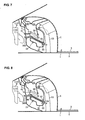
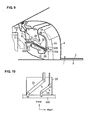
- the evaporator 22 is to be disposed preferably obliquely in such a manner that a distance between its front end and rear end is a specified (predetermined or predeterminable) length or greater. Specifically, as shown e.g. in FIG.
- an angle ⁇ formed between the maximum-area face of the evaporator 22 and a vertical face extending substantially in a vehicle vertical direction is approximately 60 degrees (an acute angle other than approximately 20 - 40 degrees, preferably in a range of between approximately 40 and 80 degrees, more preferably in a range between approximately 50 and 70 degrees) and/or an angle formed between the maximum-area face of the evaporator 22 and the instrument panel center members 53 is also approximately 60 degrees (acute angle other than approximately 20 - 40 degrees, preferably in a range of between approximately 40 and 80 degrees, more preferably in a range between approximately 50 and 70 degrees).
- the evaporator 22 is supported so as to rotate or pivot substantially around the width direction WD (clockwise in FIG. 3) substantially around its rear end at the frontal crash of the vehicle C (or so as to reduce the angle a formed between the maximum-area face of the evaporator 22 and a vertical face extending substantially in a vehicle vertical direction), and the support rigidity of the support bracket 33 supporting the rear end of the evaporator 22 is set to be greater than that of the support bracket 33 supporting the front end of the evaporator 22. If the support bracket 33 is broken, the evaporator 22 can be supported by the instrument panel center members 53.
- the length of the evaporator in the vehicle longitudinal direction LD is longer than the distance of the two instrument panel center members 53.
- Two supply pipes 38 which are made of metal (e.g., steel) are coupled to a front end portion of the evaporator 22, passing through or across or over the dash panel 7. Rear end portions of these supply pipes 38 are bent upward obliquely and their front end portions substantially extend forward horizontally. The supply pipes 38 are coupled to the lower end portion of the evaporator 22, and when the frontal crash of the vehicle C happens, the supply pipes 38 are moved rearward to promote the above-described rotation of the evaporator 22.
- metal e.g., steel
- the heater core 28 preferably is disposed above and/or substantially in parallel to the evaporator 22 as shown in FIG. 3.
- the heater core 28 preferably is made of aluminum and/or substantially formed in the flat and/or rectangular-parallelepiped shape, being smaller in size than, preferably having about half scale of the evaporator 22.
- a front end of the heater core 28 is to be supported at a support member 39 that is provided at the inner wall of the case 21, and its rear end is to be disposed at a specified (predetermined or predeterminable) location such that an aerodynamics damper 40 (opening valve), whose pivotal axis is located at the rear end of the heater core 28 and which is able to swing longitudinally, can substantially cover the upper face of the heater core 28.
- Both side ends of the heater core 28 are to be supported at the inner wall of the case 21.
- the support rigidity of the heater core 38 at the support member 39 is set to be greater than that of the heater core 38 at the above-described both sides or at an attaching portion of the pivotal axis of the damper 40.
- the heater core 28 is configured so as to be easy to rotate or pivot vertically (or substantially around the widthwise direction WD) around the support member 39 at the vehicle frontal crash.
- the heater core 28 rotates or pivots counterclockwise (or in a direction substantially opposite to the evaporator 22) in FIG. 3 substantially around the support member 39.
- supply pipes 41 which preferably are made of aluminum and whose other ends are coupled to the engine 9, passing through or across or over the dash panel 7.
- the cooling water that is heated at the engine 9 is supplied to the heater core 28 via these pipes 41.
- the operation and effects of the vehicle C with the above-described air conditioner unit 20 will be described.
- the power train 13 hits against the substantially laterally-extending portion of the supply pipes 38 and the dash panel 7, and thereby the pipes 38 and the dash panel 7 are moved rearward.
- the evaporator 22 is rotated or pivoted in a first direction (e.g. clockwise), by being pushed up between the dash panel 7 and the instrument panel center members 53, as shown by two-dotted broken lines in FIG. 3.
- the instrument panel center members 53 prevent properly the evaporator 22 substantially from further moving rearward, and thereby promotes the (clockwise) rotation of the evaporator 22. Accordingly, the evaporator 22 can be prevented from being pushed into the vehicle cabin 1, thereby ensuring a safety of passengers.
- the instrument panel center members 53 are provided behind the evaporator 22, extending at an angle different from 0° or 180°, preferably substantially normal to the vehicle longitudinal direction LD and/or width direction WD or substantially vertically, and the angle formed between the maximum-area face of the evaporator 22 and the instrument panel center members 53 preferably is set to be the acute angle. Accordingly, the evaporator 22 can be rotated or pivoted surely at the frontal crash of the vehicle C. Also, the upper ends of the instrument panel center members 53 are fixed to the instrument member 54 extending substantially in the vehicle width direction WD to support the steering wheel 5.
- the crash impact can be properly absorbed or reduced by the rotation of the evaporator 22 and/or the instrument panel 54 and the steering wheel 5 that are supported at the instrument panel center members 53 can be also prevented properly from being moved rearward, thereby further ensuring the safety of passengers.
- the steel or rigid supply pipes 38 preferably are to be coupled to the front end portion of the evaporator 22 and these pipes 38 are provided so as to promote the rotation of the evaporator 22 with a rearward movement thereof at the vehicle frontal crash.
- the rotation of the evaporator 22 can be attained surely with the supply pipes 38 moving rearward.
- the power train 13 is disposed before the supply pipes 38, so the rearward movement of the power train 13 at the vehicle frontal crash can surely cause the above-described rearward movement of the supply pipes 38.
- the heater core 28 that is small sized compared with the evaporator 22. Accordingly, the rotation of the evaporator 22 would not be prevented by the existence of the heater core 28.
- the evaporator 22 preferably is disposed in such a manner that the angle formed between the maximum-area face of the evaporator 22 and the vertical face is other than approximately 20 - 40 degrees. Accordingly, some water produced by dew condensation at peripheries of the pipes 26 and fins 27 can be made drop from the evaporator surely, and thereby the deterioration of the cooling function of the evaporator 22 can be prevented. Also, the evaporator 22 is disposed obliquely and the conditioning air flows passing through the evaporator 22 from the bottom to the upper, so the longitudinal length of the air conditioner unit 20 is made short and the flow resistance can be reduced and the air flow efficiency can be improved as well.
- a vehicle with an air conditioner comprises an instrument panel center member 53 disposed vertically behind an evaporator 22 and fixed to a vehicle structure.
- the evaporator 22 is disposed obliquely in such a manner that its maximum-area face has a crossing angle relative to a horizontal face and a distance between its front and rear ends is a specified length or greater.
- the evaporator 22 is configured so as to be rotated between a vehicle dash panel 7 being moved rearward and the instrument panel center member 53 at a frontal crash of a vehicle C in such a manner that the distance between its front end and rear end becomes shorter. Accordingly, the evaporator 22 can be prevented from being pushed into a vehicle cabin at the vehicle frontal crash, thereby ensuring the safety of the passenger.
Landscapes
- Physics & Mathematics (AREA)
- Thermal Sciences (AREA)
- Engineering & Computer Science (AREA)
- Mechanical Engineering (AREA)
- Air-Conditioning For Vehicles (AREA)
- Body Structure For Vehicles (AREA)
Applications Claiming Priority (1)
| Application Number | Priority Date | Filing Date | Title |
|---|---|---|---|
| JP2005132818A JP4656305B2 (ja) | 2005-04-28 | 2005-04-28 | 空調装置を搭載した車両 |
Publications (2)
| Publication Number | Publication Date |
|---|---|
| EP1717072A1 true EP1717072A1 (fr) | 2006-11-02 |
| EP1717072B1 EP1717072B1 (fr) | 2009-03-25 |
Family
ID=36710034
Family Applications (1)
| Application Number | Title | Priority Date | Filing Date |
|---|---|---|---|
| EP06008211A Ceased EP1717072B1 (fr) | 2005-04-28 | 2006-04-20 | Véhicule avec climatisation et méthode de montage de climatisation dans un véhicule |
Country Status (4)
| Country | Link |
|---|---|
| US (1) | US7963315B2 (fr) |
| EP (1) | EP1717072B1 (fr) |
| JP (1) | JP4656305B2 (fr) |
| DE (1) | DE602006005862D1 (fr) |
Cited By (1)
| Publication number | Priority date | Publication date | Assignee | Title |
|---|---|---|---|---|
| EP2204297A3 (fr) * | 2008-12-30 | 2010-08-04 | Seat, S.A. | Système de montage d'un équipement de climatisation dans un tableau de bord avant de véhicule |
Families Citing this family (4)
| Publication number | Priority date | Publication date | Assignee | Title |
|---|---|---|---|---|
| JP4656305B2 (ja) | 2005-04-28 | 2011-03-23 | マツダ株式会社 | 空調装置を搭載した車両 |
| DE102007019407A1 (de) * | 2006-04-25 | 2007-11-08 | Behr America, Inc., Webberville | Gehäuse für ein Heizungs- und/oder Klimaanlagenmodul und Verfahren zur Herstellung eines solchen Gehäuses |
| FR3088611B1 (fr) * | 2018-11-15 | 2020-10-30 | Renault Sas | Element structurel lacunaire pour planche de bord, traverse associee et planche de bord correspondante |
| US11136997B2 (en) | 2019-07-23 | 2021-10-05 | Ford Global Technologies, Llc | Methods and systems for a compressor housing |
Citations (9)
| Publication number | Priority date | Publication date | Assignee | Title |
|---|---|---|---|---|
| GB2065038A (en) * | 1979-11-17 | 1981-06-24 | Daimler Benz Ag | Motor vehicle with a forward engine and a heating or air-conditioning unit |
| US4437393A (en) * | 1980-06-21 | 1984-03-20 | Daimler-Benz Aktiengesellschaft | Assembly compartment arranged between an engine compartment or trunk and a splash panel of a motor vehicle |
| US4691862A (en) * | 1985-06-06 | 1987-09-08 | Nissan Motor Co., Ltd. | Heater unit for vehicles |
| US4767153A (en) * | 1986-01-09 | 1988-08-30 | Nissan Motor Co., Ltd. | Safety structure of vehicle body adjacent instrument panel |
| US5927382A (en) | 1996-09-26 | 1999-07-27 | Denso Corporation | Air conditioning apparatus for vehicle |
| US6101828A (en) * | 1997-12-25 | 2000-08-15 | Denso Corporation | Air conditioning apparatus for vehicle |
| EP1203711A2 (fr) * | 2000-11-01 | 2002-05-08 | Visteon Global Technologies, Inc. | Assemblage de support de colonne de direction d'un véhicule automobile |
| EP1241032A2 (fr) * | 2001-03-16 | 2002-09-18 | Calsonic Kansei Corporation | Climatiseur pour véhicule |
| US20050045320A1 (en) * | 2003-08-25 | 2005-03-03 | Visteon Global Technologies, Inc. | Compact vehicle temperature control system |
Family Cites Families (10)
| Publication number | Priority date | Publication date | Assignee | Title |
|---|---|---|---|---|
| JPS63176715A (ja) * | 1986-09-25 | 1988-07-21 | Mazda Motor Corp | 自動車の空調ユニツトの構造 |
| JPH1071847A (ja) * | 1996-08-30 | 1998-03-17 | Calsonic Corp | 車両用空気調和装置 |
| DE19752072A1 (de) * | 1997-11-25 | 1999-05-27 | Opel Adam Ag | Kraftfahrzeug mit einer Armaturentafel |
| US6351962B1 (en) * | 1999-12-06 | 2002-03-05 | Denso Corporation | Cockpit module assembly including air conditioner for vehicle |
| US6349561B1 (en) * | 2000-02-24 | 2002-02-26 | Visteon Global Technologies, Inc. | Refrigeration circuit for vehicular air conditioning system |
| JP2003205765A (ja) * | 2002-01-16 | 2003-07-22 | Mazda Motor Corp | 車両の空調ユニット配設構造 |
| JP4173694B2 (ja) * | 2002-06-18 | 2008-10-29 | 株式会社ケーヒン | 車両用隔壁 |
| JP2005014766A (ja) * | 2003-06-26 | 2005-01-20 | Denso Corp | 車両の衝突安全機構 |
| US7845391B2 (en) * | 2004-01-15 | 2010-12-07 | Mitsubishi Heavy Industries, Ltd. | Air-conditioning unit and vehicle air-conditioning apparatus |
| JP4656305B2 (ja) | 2005-04-28 | 2011-03-23 | マツダ株式会社 | 空調装置を搭載した車両 |
-
2005
- 2005-04-28 JP JP2005132818A patent/JP4656305B2/ja not_active Expired - Fee Related
-
2006
- 2006-04-06 US US11/398,645 patent/US7963315B2/en not_active Expired - Fee Related
- 2006-04-20 DE DE602006005862T patent/DE602006005862D1/de not_active Expired - Lifetime
- 2006-04-20 EP EP06008211A patent/EP1717072B1/fr not_active Ceased
Patent Citations (9)
| Publication number | Priority date | Publication date | Assignee | Title |
|---|---|---|---|---|
| GB2065038A (en) * | 1979-11-17 | 1981-06-24 | Daimler Benz Ag | Motor vehicle with a forward engine and a heating or air-conditioning unit |
| US4437393A (en) * | 1980-06-21 | 1984-03-20 | Daimler-Benz Aktiengesellschaft | Assembly compartment arranged between an engine compartment or trunk and a splash panel of a motor vehicle |
| US4691862A (en) * | 1985-06-06 | 1987-09-08 | Nissan Motor Co., Ltd. | Heater unit for vehicles |
| US4767153A (en) * | 1986-01-09 | 1988-08-30 | Nissan Motor Co., Ltd. | Safety structure of vehicle body adjacent instrument panel |
| US5927382A (en) | 1996-09-26 | 1999-07-27 | Denso Corporation | Air conditioning apparatus for vehicle |
| US6101828A (en) * | 1997-12-25 | 2000-08-15 | Denso Corporation | Air conditioning apparatus for vehicle |
| EP1203711A2 (fr) * | 2000-11-01 | 2002-05-08 | Visteon Global Technologies, Inc. | Assemblage de support de colonne de direction d'un véhicule automobile |
| EP1241032A2 (fr) * | 2001-03-16 | 2002-09-18 | Calsonic Kansei Corporation | Climatiseur pour véhicule |
| US20050045320A1 (en) * | 2003-08-25 | 2005-03-03 | Visteon Global Technologies, Inc. | Compact vehicle temperature control system |
Cited By (1)
| Publication number | Priority date | Publication date | Assignee | Title |
|---|---|---|---|---|
| EP2204297A3 (fr) * | 2008-12-30 | 2010-08-04 | Seat, S.A. | Système de montage d'un équipement de climatisation dans un tableau de bord avant de véhicule |
Also Published As
| Publication number | Publication date |
|---|---|
| JP4656305B2 (ja) | 2011-03-23 |
| US20060242979A1 (en) | 2006-11-02 |
| US7963315B2 (en) | 2011-06-21 |
| DE602006005862D1 (de) | 2009-05-07 |
| EP1717072B1 (fr) | 2009-03-25 |
| JP2006306310A (ja) | 2006-11-09 |
Similar Documents
| Publication | Publication Date | Title |
|---|---|---|
| JP5556619B2 (ja) | 車両用空調装置 | |
| US8240164B2 (en) | Air conditioning apparatus having a blower downstream of the heat exchangers | |
| CN100387451C (zh) | 空气调节单元以及车辆空气调节装置 | |
| US6796368B1 (en) | Air conditioning apparatus for vehicle | |
| US20150118948A1 (en) | Air passage opening/closing device | |
| JP2005219531A (ja) | 車両用熱交換器冷却装置 | |
| WO2021075258A1 (fr) | Système de climatisation de véhicule automobile | |
| EP1717072B1 (fr) | Véhicule avec climatisation et méthode de montage de climatisation dans un véhicule | |
| JP3791126B2 (ja) | 車両用空調装置 | |
| JP3799647B2 (ja) | 自動車用空調装置 | |
| JP3817333B2 (ja) | 自動車用空気調和装置 | |
| JP5127204B2 (ja) | 車両用空調装置 | |
| JP3820650B2 (ja) | 車両用空調装置 | |
| JP4013383B2 (ja) | 車両用空調装置 | |
| JP2006199214A (ja) | キャビンのダクト構造 | |
| JP3986501B2 (ja) | 空気調和ユニットおよび車両用空気調和装置 | |
| JP2008044485A (ja) | 車両用空調装置を搭載した車両 | |
| JP4013114B2 (ja) | 車両の空調ユニット配設構造 | |
| JP4397614B2 (ja) | 車両用空調装置 | |
| JP2019006176A (ja) | 車両用空調装置 | |
| JP2026011658A (ja) | 消音装置の取付構造 | |
| JP3574100B2 (ja) | 車両用空調装置 | |
| JP2000225836A (ja) | 車両用空調装置 | |
| JP2000043551A (ja) | 車両用空調装置 | |
| JP2005029049A (ja) | 車両用空調装置 |
Legal Events
| Date | Code | Title | Description |
|---|---|---|---|
| PUAI | Public reference made under article 153(3) epc to a published international application that has entered the european phase |
Free format text: ORIGINAL CODE: 0009012 |
|
| AK | Designated contracting states |
Kind code of ref document: A1 Designated state(s): AT BE BG CH CY CZ DE DK EE ES FI FR GB GR HU IE IS IT LI LT LU LV MC NL PL PT RO SE SI SK TR |
|
| AX | Request for extension of the european patent |
Extension state: AL BA HR MK YU |
|
| 17P | Request for examination filed |
Effective date: 20070405 |
|
| 17Q | First examination report despatched |
Effective date: 20070515 |
|
| AKX | Designation fees paid |
Designated state(s): DE |
|
| GRAP | Despatch of communication of intention to grant a patent |
Free format text: ORIGINAL CODE: EPIDOSNIGR1 |
|
| GRAS | Grant fee paid |
Free format text: ORIGINAL CODE: EPIDOSNIGR3 |
|
| GRAA | (expected) grant |
Free format text: ORIGINAL CODE: 0009210 |
|
| AK | Designated contracting states |
Kind code of ref document: B1 Designated state(s): DE |
|
| REF | Corresponds to: |
Ref document number: 602006005862 Country of ref document: DE Date of ref document: 20090507 Kind code of ref document: P |
|
| PLBE | No opposition filed within time limit |
Free format text: ORIGINAL CODE: 0009261 |
|
| STAA | Information on the status of an ep patent application or granted ep patent |
Free format text: STATUS: NO OPPOSITION FILED WITHIN TIME LIMIT |
|
| 26N | No opposition filed |
Effective date: 20091229 |
|
| PGFP | Annual fee paid to national office [announced via postgrant information from national office to epo] |
Ref country code: DE Payment date: 20180410 Year of fee payment: 13 |
|
| REG | Reference to a national code |
Ref country code: DE Ref legal event code: R119 Ref document number: 602006005862 Country of ref document: DE |
|
| PG25 | Lapsed in a contracting state [announced via postgrant information from national office to epo] |
Ref country code: DE Free format text: LAPSE BECAUSE OF NON-PAYMENT OF DUE FEES Effective date: 20191101 |