EP1717103B1 - Rétroviseur pour véhicule automobile - Google Patents
Rétroviseur pour véhicule automobile Download PDFInfo
- Publication number
- EP1717103B1 EP1717103B1 EP20060008147 EP06008147A EP1717103B1 EP 1717103 B1 EP1717103 B1 EP 1717103B1 EP 20060008147 EP20060008147 EP 20060008147 EP 06008147 A EP06008147 A EP 06008147A EP 1717103 B1 EP1717103 B1 EP 1717103B1
- Authority
- EP
- European Patent Office
- Prior art keywords
- rearview mirror
- contact
- glass
- mirror
- contact element
- Prior art date
- Legal status (The legal status is an assumption and is not a legal conclusion. Google has not performed a legal analysis and makes no representation as to the accuracy of the status listed.)
- Ceased
Links
Images


Classifications
-
- B—PERFORMING OPERATIONS; TRANSPORTING
- B60—VEHICLES IN GENERAL
- B60R—VEHICLES, VEHICLE FITTINGS, OR VEHICLE PARTS, NOT OTHERWISE PROVIDED FOR
- B60R1/00—Optical viewing arrangements; Real-time viewing arrangements for drivers or passengers using optical image capturing systems, e.g. cameras or video systems specially adapted for use in or on vehicles
- B60R1/02—Rear-view mirror arrangements
- B60R1/06—Rear-view mirror arrangements mounted on vehicle exterior
- B60R1/062—Rear-view mirror arrangements mounted on vehicle exterior with remote control for adjusting position
- B60R1/07—Rear-view mirror arrangements mounted on vehicle exterior with remote control for adjusting position by electrically powered actuators
Definitions
- the invention relates to a rearview mirror for a motor vehicle according to the preamble of claim 1.
- Generic rearview mirrors are used in motor vehicles as an interior rearview mirror or as an exterior rearview mirror to allow the driver in the mirror glass of the glass assembly to observe the subsequent traffic.
- a large number of electrical functional elements are integrated into the rearview mirrors. These may be lighting devices, antennas, mirror heaters, electro-chromatically dimmable mirror glasses or other additional functional elements.
- a motorized adjustment of the glass assembly by means of a Glasverstellantriebs is often provided, the drive motors must be electrically connected to the electrical system.
- the lines to the various functional elements of the rearview mirror can be separated at suitable locations, contact elements being provided at each of the line ends.
- these contact points are then contacted with one another in order to ensure the electrical functionality of the electrical functional elements.
- the US 6,247,823 B1 describes a rearview mirror with a plug-in contact.
- the plug of the plug-in contact are aligned such that insertion of the plug is realized in correspondingly arranged sockets by the joining movement.
- the EP 1 370 443 B1 describes a sliding contact for automatically connecting a mirror heater during assembly of the mirror glass on a support plate.
- a disadvantage of the known rear-view mirrors is that the mounting of the rearview mirror is made considerably more difficult by contacting the contact points.
- cable tails are provided with connectors on the various functional elements, which must be mounted by hand during assembly of the rearview mirror. By this separate installation of the contact elements of the assembly effort is significantly increased.
- a rational and largely fully automated assembly of the rearview mirror is thus largely excluded.
- a disadvantage of the known contact-making contactable with the joining movement is that, with the slightest inaccuracies, even a single connector makes assembly impossible. This danger is particularly great when a variety of plugs must be plugged in at the same time.
- the rearview mirror is based on the basic idea that the contact elements at the line ends, at which the electrical line can be separated, are each fixed to a component, these components being joined together during assembly of the rearview mirror.
- the two contact elements are inventively arranged and dimensioned according to the invention such that the mutually associated contact points of the two contact elements are contacted by the joining movement of the components in the assembly of the rearview mirror with each other. This means, in other words, that the electrical contacting is readily produced by the mechanical joining of the corresponding components during mirror mounting at the same time and without additional installation effort. In this way, the separate mounting of the contact elements for the production of electrical functionality can be saved.
- the contact point of at least one first contact element is designed in the manner of a flat conductor track.
- This flat conductor track is arranged on a suitable carrier element, for example on a printed circuit board or a carrier foil.
- a suitable carrier element for example on a printed circuit board or a carrier foil.
- the associated second contact element is placed from above and thereby created in the contact surface of the electrically conductive contact.
- a first contact element is fixed to the rearview mirror itself.
- the housing of the rearview mirror or the amplifier plate provided in the rearview mirror are suitable for this purpose.
- the associated second contact element is arranged opposite to a provided for fixing the rearview mirror to the vehicle body mirror. In this way, it is then possible that the contact of the provided in the rearview mirror electrical functional elements with the electrical system of the vehicle is ensured only by the attachment of the rearview mirror on the mirror.
- the first contact element is in turn fixed on the rearview mirror itself, in particular on the housing or on the intensifier plate of the rearview mirror.
- the associated second contact element is arranged in this alternative embodiment of Glasverstellantrieb so that by mounting the Glasverstellantriebs in the rearview mirror, in particular by attachment to the housing of the rearview mirror or on the amplifier plate of the rearview mirror, the drive motors located in Glasverstellantrieb be contacted without further ado.
- a first contact element is fixed to the rear side of the glass assembly and is contacted with an associated second contact element, which is arranged on Glasverstellantrieb.
- the electrical functional elements integrated in the glass assembly preferably a mirror heater and / or an electrochromically dimmable mirror glass, can be contacted with the electrical supply lines which are looped through the glass adjustment drive.
- the purpose intended second contact element should be releasably secured to Glasverstellantrieb.
- the second contact element can then optionally be mounted or omitted.
- a structurally identical Glasverstellantrieb can be installed, wherein the second contact element is then not mounted on Glasverstellantrieb. Only in embodiments with electrical functional elements in the glass assembly, the second contact element is mounted on Glasverstellantrieb to ensure electrical contact with the glass assembly.
- a support plate is often provided, which is arranged on the back of the glass assembly and positively and / or non-positively fixed to the Glasverstellantrieb, in particular can be plugged.
- These carrier plates are usually made of plastic, which represents an electrical insulation.
- the carrier plate should preferably have a recess. Through this recess then the provided on the glass assembly contact points can be contacted.
- the heating conductor foil is supplied on a roll.
- the protective film is peeled off over the adhesive surface of the heating conductor foil.
- the heating conductor foil is pre-punched with positioning marks and in this way makes it possible to position the heating conductor foil in the correct position over the carrier plate in a very simple manner.
- the first held in a stamped grid Edelleiterfolie is pressed against the support plate and separated out in this way from the stamped grid. Subsequently, the mirror glass can be glued in the same way on the opposite side of the Schuleiterfolie. The entire assembly process of the glass assembly can be carried out largely automatically in this way.
- the contact element for contacting the electrochromic mirror glass should also be integrated into the Schuleiterfolie, so made by suitable contacting these the contact points forming flat conductor tracks at the same time the electrical system contact for mirror heating and the electrochromic mirror glass can be.
- a further prefabricated contact point has to be provided between the electrochromic mirror glass and the heating conductor foil in order to connect the conductor track element provided for contacting the mirror glass to the heating conductor foil at the opposite end to the electrochromic mirror glass.
- the electrical contact between the electrochromic mirror glass and heating conductor foil can optionally be in the form of a solder joint, be formed of an electrically conductive adhesive bond or in the manner of an electrically conductive press connection.
- the opposite second contact element In order to be able to reliably contact the flat conductor track serving as a contact point, the opposite second contact element must have a corresponding construction.
- resiliently mounted contact tongues for electrical contacting to flat conductor tracks have proven to be suitable.
- During assembly of the two components reach the contact tongues from above on the flat conductor track and are pressed elastically due to their resilient mounting against the flat conductor track. Due to the elastic bias of the reeds after assembly electrical contact is reliably ensured even with strong vibrations and prolonged use.
- a sealing element for protecting the contacted contact points from moisture should preferably be provided on the second contact element, for example an adapter carrying the contact tongues.
- the sealing element should preferably be designed in the manner of a closed sealing ring, which can embrace a plurality of contacted contact points in this way.
- the sealing ring should preferably be designed in the manner of a cellular rubber seal or in the manner of a sealing lip.
- a sealing gel in addition to the use of a sealing ring in the space between the sealing ring and the Contact points are arranged a sealing gel. Through the sealing gel moisture, which has overcome the barrier of the sealing ring, held away from the contact points.
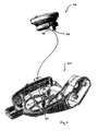
- Fig. 1 an intensifier plate 01 and a Glasverstellantrieb 02 of an outside rearview mirror of a vehicle is shown in perspective.
- the other parts of the outside rearview mirror, which are not required to understand the invention are in Fig. 1 not shown.
- the glass adjusting drive 03 is inserted from above into the intensifier plate 01 and fixed in the screw base 03 by screwing in a fastening screw.
- electrical lines are embedded in the plastic body of the amplifier plate 01. The one end of these electrical lines is contacted during assembly of the amplifier plate to a mirror base with the electrical system of the vehicle.
- the respective opposite end of the electrical leads to a arranged on the inside of the amplifier plate 01 contact element 04, which has a total of eight plug contacts 05.
- At Glasverstellantrieb 02 in turn another contact element 06 is present on the hidden shown a total of eight plug contacts 07 are provided.
- unrecognizable plug contacts 07 on the contact element 06 are provided for making electrical contact with the electrical adjustment elements provided in the glass adjustment drive 02, in particular the drive motors.
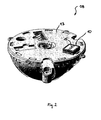
- Fig. 2 shows another, Glasverstellantrieb 08 invention
- the electromechanical adjustment of the in Fig. 3 illustrated glass assembly 09 is provided.
- a contact element 10 is attached, which serves the electrical contacting of the provided on the glass assembly 09 electrical functional elements.
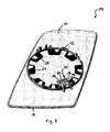
- the glass assembly 09 points to its in Fig. 3 shown back on a support plate 11, which serves the mechanical attachment of the glass assembly 09 on Glasverstellantrieb 08.
- a circular adapter ring 12 is formed, which is attached to the circular support plate 13 of the Glasverstellantriebs 08 during assembly of the rearview mirror.
- On the support plate 11 of the glass assembly 09 opposite and in Fig. 3 not shown page is required to observe the subsequent traffic mirror glass 14 is fixed, from the in Fig. 3 only the outer edge can be seen.
- the mirror glass 14 has as an optional feature on an electro-chromatic Spiegelglasabblendung.
- a mirror heating in the form of a Bankleiterfolie 21 is provided between the mirror glass 14 and the support plate 11.
- the contact element 10 For contacting the provided in the glass assembly 09 electrical functional elements, namely the mirror heating and the electrochromic Spiegelglasabblendung with the electrical system, the contact element 10 has four spring-mounted contact tongues 15, which serve as contact points.
- the contact tongues 15 electrically conductive on Flachleiterbahnenden 16, 17, 18 and 19 to the system, which together form a contact element 32 for electrical contacting of the glass assembly 09.
- the carrier plate 11 in the region of the flat conductor track ends 16, 17, 18 and 19 has a recess 20 which can be penetrated by the outer contour of the contact element 10.
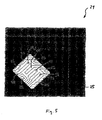
- the flat conductor track ends 16, 17, 18 and 19 are part of the track layout on a heating conductor foil 21, which in Fig. 4 and Fig. 5 is shown in more detail.
- a heating conductor foil 21 which in Fig. 4 and Fig. 5 is shown in more detail.
- a carrier foil 22 see Fig. 5 .
- Various flat conductor tracks are arranged and form Bankffleander 23, which serve as mirror heating.
- the Schuffleander 23 end up in the flat conductor ends 16 and 17, so that the mirror heating by contacting the contact points in the flat conductor ends 16 and 17 can be connected to the electrical system.
- Two further flat conductor tracks, which open into the flat conductor track ends 18 and 19, serve for electrical connection of the electrochromic mirror glass 14.
- the contact element 10 is releasably attached to the Glasverstellantrieb 08, for example, clipped, so that in embodiments that have no mirror heating and no electrochromic mirror glass, the same Glasverstellantrieb 08 can be used, in these basic versions without optional features, the contact element 10 then not on Glasverstellantrieb 08 is mounted.
- Fig. 6 the contact element 10 is shown enlarged with the contact tongues 15.
- the contact element 10 can be clipped by means of clip hooks 27 from above on the holding plate 13 of the Glasverstellantriebs 08.
- the contact tongues 15 are connected to the electrical system of the vehicle.
- a sealing ring 29 made of cellular rubber is arranged on the outer circumference of the contact element 10. This sealing ring arrives during assembly of the glass assembly 09 on Glasverstellantrieb 08 on the upper side of the Schuleiterfolie 21 in the region of the cutout 26 to the plant and protects the contact points between the flat conductor ends 16, 17, 18 and 19 with the opposite contact tongues 15 from penetrating moisture.
- a sealing gel pad 30 is provided in the intermediate space between the contact tongues 15 and the sealing ring 29.
- Fig. 7 shows a second embodiment 10a of a contact element, which differs from the first embodiment 10 in that the moisture protection is ensured by an annular sealing lip 31.
- a sealant pad 30 may optionally be omitted in the embodiment 10a.
Landscapes
- Engineering & Computer Science (AREA)
- Multimedia (AREA)
- Mechanical Engineering (AREA)
- Rear-View Mirror Devices That Are Mounted On The Exterior Of The Vehicle (AREA)
- Electrochromic Elements, Electrophoresis, Or Variable Reflection Or Absorption Elements (AREA)
Claims (17)
- Rétroviseur pour un véhicule automobile, comprenant un ensemble de glace pour l'observation du trafic en arrière et comprenant au moins un élément fonctionnel électrique qui peut être raccordé via au moins une ligne électrique au réseau de bord du véhicule ou à d'autres éléments fonctionnels électriques, au moins un point de séparation étant prévu dans la ligne, dans lequel la ligne peut être séparée en formant deux extrémités de ligne, des éléments de contact étant respectivement prévus auxdites extrémités de ligne, les points de contact des extrémités de ligne étant mis en contact entre eux de manière électriquement conductrice lors du montage du rétroviseur, les éléments de contact (04, 06, 10, 32) étant chacun fixés à un composant (01, 02, 08, 09), les composants (01, 02, 08, 09) étant assemblés les uns avec les autres lors du montage du rétroviseur, les deux éléments de contact (04, 06, 10, 32) étant agencés aux composants (01, 02, 08, 09) de telle manière que les points de contact (05, 07, 15, 16, 17, 18, 19) associés les uns aux autres des deux éléments de contact (04, 06, 10, 32) sont mis en contact entre eux par le mouvement d'assemblage des composants (01, 02, 08, 09) lors du montage du rétroviseur,
caractérisé en ce que
le point de contact (16, 17, 18, 19) d'au moins un premier élément de contact (32) est conçu en forme d'une piste conductrice méplate, qui avec son côté inférieur est agencée sur un élément de support, en particulier une feuille de support (22), et qui dans au moins une région de son côté supérieur, en particulier à l'extrémité de la piste conductrice méplate, peut être mise en contact électrique avec le point de contact (15) d'un second élément de contact (10) associé. - Rétroviseur selon la revendication 1,
caractérisé en ce qu'
un premier élément de contact est fixé au rétroviseur, en particulier au boîtier ou à la plaque amplificatrice (01) du rétroviseur, et un second élément de contact (06) associé est fixé à un pied du rétroviseur qui est prévu à la carrosserie du véhicule pour fixer le rétroviseur. - Rétroviseur selon la revendication 1 ou 2,
caractérisé en ce qu'
un premier élément de contact (05) est fixé au rétroviseur, en particulier au boîtier ou à la plaque amplificatrice (01) du rétroviseur, et un second élément de contact (06) associé est fixé à un entraînement d'ajustage de glace (02). - Rétroviseur selon l'une quelconque des revendications 1 à 3,
caractérisé en ce qu'
un premier élément de contact (32) est fixé au côté postérieur de l'ensemble de glace (09), et un second élément de contact associé (10) est fixé à l'entraînement d'ajustage de glace (08). - Rétroviseur selon la revendication 4,
caractérisé en ce qu'
un chauffage de rétroviseur (21) actionné électriquement et/ou une glace (14) électrochromatique est/sont prévu(e)/s à l'ensemble de glace (09), le chauffage de rétroviseur (21) et/ou la glace électrochromatique (14) peut/peuvent être relié(e)/s au réseau de bord de manière directe ou indirecte via les deux éléments de contact (10, 15) associés. - Rétroviseur selon la revendication 4 ou 5,
caractérisé en ce que
le second élément de contact (10) est fixé à l'entraînement d'ajustage de glace (08) de manière détachable, et est monté seulement optionnellement en fonction de caractéristiques d'équipement spéciales de l'ensemble de glace (09). - Rétroviseur selon l'une quelconque des revendications 4 à 6,
caractérisé en ce que
pour la fixation de l'ensemble de glace (09), une plaque de support (11) est prévue à l'entraînement d'ajustage de glace (08), la plaque de support étant agencée au côté postérieur de l'ensemble de glace (09) et pouvant être fixée, en particulier enfichée, à l'entraînement d'ajustage de glace (08) par engagement positif et/ou par adhérence, la plaque de support (11) présentant un évidement (20) via lequel les points de contact (16, 17, 18, 19) prévus à l'ensemble de glace (09) peuvent être mis en contact. - Rétroviseur selon la revendication 7,
caractérisé en ce que
la feuille de support (22) appartient à une feuille de conducteur chauffant (21) faisant office de chauffage de rétroviseur. - Rétroviseur selon la revendication 8,
caractérisé en ce que
la feuille de conducteur chauffant (21) est fixée à la glace (14) et/ou à la plaque de support (11) au moyen d'une couche adhésive. - Rétroviseur selon la revendication 8 ou 9,
caractérisé en ce que
les points de contact (18, 19) sont intégrés dans l'élément de contact (32) de la feuille de conducteur chauffant (21) pour la mise en contact de la glace électrochromatique prévue à l'ensemble de glace (09), la glace électrochromatique (14) étant mise en contact électrique avec la feuille de conducteur chauffant (21) à au moins un autre point de contact (24). - Rétroviseur selon la revendication 10,
caractérisé en ce que
la glace électrochromatique (14) est mise en contact électrique avec la feuille de conducteur chauffant (21) par une connexion par brasage (24), par une connexion adhésive étant électriquement conductrice ou bien par une connexion de pression étant électriquement conductrice. - Rétroviseur selon l'une quelconque des revendications 7 à 11,
caractérisé en ce que
le second élément de contact (10) présente un moins une languette de contact (15) montée de manière élastique pour la mise en contact du point de contact (16, 17, 18, 19) formé par une piste conductrice méplate. - Rétroviseur selon l'une quelconque des revendications 7 à 12,
caractérisé en ce qu'
un élément d'étanchéité (29, 31) pour protéger contre l'humidité les points de contact (16, 17, 18, 19) qui ont été mis en contact est prévu au second élément de contact (10) pour la mise en contact d'un point de contact (16, 17, 18, 19) formé par une piste conductrice méplate. - Rétroviseur selon la revendication 13,
caractérisé en ce que
l'élément d'étanchéité (29, 31) entoure plusieurs points de contact (16, 17, 18, 19) qui ont été mis en contact de manière étanche au moyen d'une bague d'étanchéité close. - Rétroviseur selon la revendication 14,
caractérisé en ce que
la bague d'étanchéité est conçue sous forme d'un joint en caoutchouc cellulaire (29) ou sous forme d'une lèvre d'étanchéité (31). - Rétroviseur selon la revendication 14,
caractérisé en ce que
l'espace entre la bague d'étanchéité (29) et les points de contact (16, 17, 18, 19) qui ont été mis en contact est rempli avec un gel d'étanchéité (30) supplémentaire. - Rétroviseur selon l'une quelconque des revendications 1 à 16,
caractérisé en ce que
le rétroviseur est conçu sous forme d'un rétroviseur extérieur.
Applications Claiming Priority (1)
| Application Number | Priority Date | Filing Date | Title |
|---|---|---|---|
| DE200510020013 DE102005020013B3 (de) | 2005-04-27 | 2005-04-27 | Rückspiegel für ein Kraftfahrzeug |
Publications (3)
| Publication Number | Publication Date |
|---|---|
| EP1717103A1 EP1717103A1 (fr) | 2006-11-02 |
| EP1717103A8 EP1717103A8 (fr) | 2006-12-27 |
| EP1717103B1 true EP1717103B1 (fr) | 2012-03-28 |
Family
ID=36847873
Family Applications (1)
| Application Number | Title | Priority Date | Filing Date |
|---|---|---|---|
| EP20060008147 Ceased EP1717103B1 (fr) | 2005-04-27 | 2006-04-20 | Rétroviseur pour véhicule automobile |
Country Status (2)
| Country | Link |
|---|---|
| EP (1) | EP1717103B1 (fr) |
| DE (1) | DE102005020013B3 (fr) |
Families Citing this family (3)
| Publication number | Priority date | Publication date | Assignee | Title |
|---|---|---|---|---|
| EP2112022B2 (fr) † | 2008-04-23 | 2014-12-10 | SMR Patents S.à.r.l. | Miroir en verre plastique pour véhicules |
| EP2399781B1 (fr) * | 2010-06-28 | 2013-01-02 | SMR Patents S.à.r.l. | Rétroviseur extérieur doté d'une liaison électrique vers un composant électrique hébergé dans le boîtier du rétroviseur extérieur |
| EP2738043B1 (fr) * | 2012-12-03 | 2015-07-22 | SMR Patents S.à.r.l. | Boîtier et dispositif d'affichage |
Family Cites Families (6)
| Publication number | Priority date | Publication date | Assignee | Title |
|---|---|---|---|---|
| DE3812993A1 (de) * | 1988-04-19 | 1989-11-02 | Bernhard Mittelhaeuser | Aussenrueckblickspiegel fuer kraftfahrzeuge |
| DE29620775U1 (de) * | 1996-11-29 | 1998-03-26 | Hohe GmbH & Co. KG, 97903 Collenberg | Außenspiegel für ein Fahrzeug |
| DE19844269B4 (de) * | 1998-09-26 | 2005-04-07 | Reitter & Schefenacker Gmbh & Co. Kg | Verstellvorrichtung für einen Außenpiegel für Kraftfahrzeuge |
| DE19928384A1 (de) * | 1999-06-21 | 2001-01-11 | Hohe Gmbh & Co Kg | Außenrückspiegel mit Trockenkammer |
| DE29915896U1 (de) * | 1999-09-10 | 1999-12-16 | Donnelly Hohe GmbH & Co. KG, 97903 Collenberg | Außenrückspiegel mit elektrischem Steckkontakt |
| DE10049954A1 (de) * | 2000-10-10 | 2002-05-08 | Buhler Motor Gmbh | Kraftfahrzeug-Rückblickspiegel |
-
2005
- 2005-04-27 DE DE200510020013 patent/DE102005020013B3/de not_active Expired - Fee Related
-
2006
- 2006-04-20 EP EP20060008147 patent/EP1717103B1/fr not_active Ceased
Also Published As
| Publication number | Publication date |
|---|---|
| EP1717103A8 (fr) | 2006-12-27 |
| DE102005020013B3 (de) | 2006-12-07 |
| EP1717103A1 (fr) | 2006-11-02 |
Similar Documents
| Publication | Publication Date | Title |
|---|---|---|
| DE102004031707B4 (de) | Intelligenter Anschlusskasten für Kraftfahrzeuge | |
| DE19841551B4 (de) | Elektrischer Rückspiegel | |
| EP2294624B1 (fr) | Boîte de jonction pour modules photovoltaïques | |
| DE102004025627A1 (de) | Solarmodul mit Anschlusselement | |
| EP0839687B1 (fr) | Rétroviseur extérieur pour véhicules | |
| EP1854168B1 (fr) | Antenne en feuille pour un vehicule | |
| EP2091113B1 (fr) | Système de raccordement pour bandes lumineuses ou lampes | |
| DE10157434B4 (de) | Schaltungsanordnung zum Steuern elektrischer Vorrichtungen in einem Fahrzeug | |
| DE29711539U1 (de) | Motorisch verstellbarer Fahrzeug-Rückspiegel | |
| DE4429983C1 (de) | Elektrisches oder elektronisches Gerät für ein Kraftfahrzeug | |
| DE20113304U1 (de) | Fahrzeuginnenraummodul | |
| WO2007113030A1 (fr) | Module de raccordement pour raccorder une unité de commande ou équivalent à une unité d'entraînement | |
| DE10111371A1 (de) | Felxible Flachbandleitung und Verfahren zum Anschluss eines elektrischen Funktionsbauteils an eine flexible Flachbandleitung | |
| EP0818133A1 (fr) | Unite de commande d'un vehicule automobile | |
| DE19844269A1 (de) | Verstellvorrichtung für einen Außenrückspiegel für Kraftfahrzeuge | |
| EP1717103B1 (fr) | Rétroviseur pour véhicule automobile | |
| DE3901307C2 (de) | Elektrische Anschlußklemme | |
| DE19819056C1 (de) | Steckverbinder für elektrische Flachleitungen | |
| DE2539379C3 (de) | Vorrichtung zum Anschließen und Haltern eines Transistors an eine gedruckte Schaltung | |
| DE102007002193B4 (de) | Mehrteiliges Kontaktierungsbauteil | |
| DE112022001496T5 (de) | Kamerahalterungsbaugruppe | |
| DE102005033593B3 (de) | Kontaktfeder in einem Trägerrahmen eines Antennenverstärkers eines Fahrzeuges | |
| EP3192155A1 (fr) | Moteur électrique pourvu de composants cms et élément de liaison associé | |
| DE19700057C2 (de) | Datenschiene für den Europäischen Installationsbus (EIB) | |
| DE10034615C2 (de) | Verfahren zum Ausbilden eines Steckverbinders aus einer elektrischen Flachleitung sowie Steckverbinder erstellt durch dieses Verfahren sowie Tragekörper zur Ausbildung eines solchen Steckverbinders |
Legal Events
| Date | Code | Title | Description |
|---|---|---|---|
| PUAI | Public reference made under article 153(3) epc to a published international application that has entered the european phase |
Free format text: ORIGINAL CODE: 0009012 |
|
| AK | Designated contracting states |
Kind code of ref document: A1 Designated state(s): AT BE BG CH CY CZ DE DK EE ES FI FR GB GR HU IE IS IT LI LT LU LV MC NL PL PT RO SE SI SK TR |
|
| AX | Request for extension of the european patent |
Extension state: AL BA HR MK YU |
|
| 17P | Request for examination filed |
Effective date: 20061207 |
|
| 17Q | First examination report despatched |
Effective date: 20070122 |
|
| TPAC | Observations filed by third parties |
Free format text: ORIGINAL CODE: EPIDOSNTIPA |
|
| AKX | Designation fees paid |
Designated state(s): DE FR GB |
|
| GRAP | Despatch of communication of intention to grant a patent |
Free format text: ORIGINAL CODE: EPIDOSNIGR1 |
|
| RAP1 | Party data changed (applicant data changed or rights of an application transferred) |
Owner name: MAGNA MIRRORS HOLDING GMBH |
|
| GRAS | Grant fee paid |
Free format text: ORIGINAL CODE: EPIDOSNIGR3 |
|
| GRAA | (expected) grant |
Free format text: ORIGINAL CODE: 0009210 |
|
| AK | Designated contracting states |
Kind code of ref document: B1 Designated state(s): DE FR GB |
|
| REG | Reference to a national code |
Ref country code: GB Ref legal event code: FG4D Free format text: NOT ENGLISH |
|
| REG | Reference to a national code |
Ref country code: DE Ref legal event code: R096 Ref document number: 502006011191 Country of ref document: DE Effective date: 20120524 |
|
| REG | Reference to a national code |
Ref country code: DE Ref legal event code: R097 Ref document number: 502006011191 Country of ref document: DE |
|
| PLBE | No opposition filed within time limit |
Free format text: ORIGINAL CODE: 0009261 |
|
| STAA | Information on the status of an ep patent application or granted ep patent |
Free format text: STATUS: NO OPPOSITION FILED WITHIN TIME LIMIT |
|
| 26N | No opposition filed |
Effective date: 20130103 |
|
| REG | Reference to a national code |
Ref country code: DE Ref legal event code: R082 Ref document number: 502006011191 Country of ref document: DE Representative=s name: , Ref country code: DE Ref legal event code: R082 Ref document number: 502006011191 Country of ref document: DE |
|
| REG | Reference to a national code |
Ref country code: DE Ref legal event code: R097 Ref document number: 502006011191 Country of ref document: DE Effective date: 20130103 |
|
| REG | Reference to a national code |
Ref country code: FR Ref legal event code: PLFP Year of fee payment: 11 |
|
| REG | Reference to a national code |
Ref country code: FR Ref legal event code: PLFP Year of fee payment: 12 |
|
| REG | Reference to a national code |
Ref country code: FR Ref legal event code: PLFP Year of fee payment: 13 |
|
| PGFP | Annual fee paid to national office [announced via postgrant information from national office to epo] |
Ref country code: FR Payment date: 20180420 Year of fee payment: 13 |
|
| PGFP | Annual fee paid to national office [announced via postgrant information from national office to epo] |
Ref country code: GB Payment date: 20180418 Year of fee payment: 13 |
|
| GBPC | Gb: european patent ceased through non-payment of renewal fee |
Effective date: 20190420 |
|
| PG25 | Lapsed in a contracting state [announced via postgrant information from national office to epo] |
Ref country code: GB Free format text: LAPSE BECAUSE OF NON-PAYMENT OF DUE FEES Effective date: 20190420 |
|
| PG25 | Lapsed in a contracting state [announced via postgrant information from national office to epo] |
Ref country code: FR Free format text: LAPSE BECAUSE OF NON-PAYMENT OF DUE FEES Effective date: 20190430 |
|
| PGFP | Annual fee paid to national office [announced via postgrant information from national office to epo] |
Ref country code: DE Payment date: 20240418 Year of fee payment: 19 |
|
| REG | Reference to a national code |
Ref country code: DE Ref legal event code: R119 Ref document number: 502006011191 Country of ref document: DE |
|
| PG25 | Lapsed in a contracting state [announced via postgrant information from national office to epo] |
Ref country code: DE Free format text: LAPSE BECAUSE OF NON-PAYMENT OF DUE FEES Effective date: 20251104 |