EP1717824A2 - Contrôleur d'un solénoide - Google Patents
Contrôleur d'un solénoide Download PDFInfo
- Publication number
- EP1717824A2 EP1717824A2 EP06075866A EP06075866A EP1717824A2 EP 1717824 A2 EP1717824 A2 EP 1717824A2 EP 06075866 A EP06075866 A EP 06075866A EP 06075866 A EP06075866 A EP 06075866A EP 1717824 A2 EP1717824 A2 EP 1717824A2
- Authority
- EP
- European Patent Office
- Prior art keywords
- terminal
- solenoid
- injector
- capacitor
- switching device
- Prior art date
- Legal status (The legal status is an assumption and is not a legal conclusion. Google has not performed a legal analysis and makes no representation as to the accuracy of the status listed.)
- Withdrawn
Links
Images




Classifications
-
- F—MECHANICAL ENGINEERING; LIGHTING; HEATING; WEAPONS; BLASTING
- F02—COMBUSTION ENGINES; HOT-GAS OR COMBUSTION-PRODUCT ENGINE PLANTS
- F02D—CONTROLLING COMBUSTION ENGINES
- F02D41/00—Electrical control of supply of combustible mixture or its constituents
- F02D41/20—Output circuits, e.g. for controlling currents in command coils
-
- H—ELECTRICITY
- H01—ELECTRIC ELEMENTS
- H01F—MAGNETS; INDUCTANCES; TRANSFORMERS; SELECTION OF MATERIALS FOR THEIR MAGNETIC PROPERTIES
- H01F7/00—Magnets
- H01F7/06—Electromagnets; Actuators including electromagnets
- H01F7/08—Electromagnets; Actuators including electromagnets with armatures
- H01F7/18—Circuit arrangements for obtaining desired operating characteristics, e.g. for slow operation, for sequential energisation of windings, for high-speed energisation of windings
- H01F7/1805—Circuit arrangements for holding the operation of electromagnets or for holding the armature in attracted position with reduced energising current
- H01F7/1816—Circuit arrangements for holding the operation of electromagnets or for holding the armature in attracted position with reduced energising current making use of an energy accumulator
-
- H—ELECTRICITY
- H01—ELECTRIC ELEMENTS
- H01F—MAGNETS; INDUCTANCES; TRANSFORMERS; SELECTION OF MATERIALS FOR THEIR MAGNETIC PROPERTIES
- H01F7/00—Magnets
- H01F7/06—Electromagnets; Actuators including electromagnets
- H01F7/08—Electromagnets; Actuators including electromagnets with armatures
- H01F7/18—Circuit arrangements for obtaining desired operating characteristics, e.g. for slow operation, for sequential energisation of windings, for high-speed energisation of windings
- H01F7/1844—Monitoring or fail-safe circuits
-
- F—MECHANICAL ENGINEERING; LIGHTING; HEATING; WEAPONS; BLASTING
- F02—COMBUSTION ENGINES; HOT-GAS OR COMBUSTION-PRODUCT ENGINE PLANTS
- F02D—CONTROLLING COMBUSTION ENGINES
- F02D41/00—Electrical control of supply of combustible mixture or its constituents
- F02D41/20—Output circuits, e.g. for controlling currents in command coils
- F02D2041/2003—Output circuits, e.g. for controlling currents in command coils using means for creating a boost voltage, i.e. generation or use of a voltage higher than the battery voltage, e.g. to speed up injector opening
- F02D2041/2006—Output circuits, e.g. for controlling currents in command coils using means for creating a boost voltage, i.e. generation or use of a voltage higher than the battery voltage, e.g. to speed up injector opening by using a boost capacitor
-
- F—MECHANICAL ENGINEERING; LIGHTING; HEATING; WEAPONS; BLASTING
- F02—COMBUSTION ENGINES; HOT-GAS OR COMBUSTION-PRODUCT ENGINE PLANTS
- F02D—CONTROLLING COMBUSTION ENGINES
- F02D41/00—Electrical control of supply of combustible mixture or its constituents
- F02D41/20—Output circuits, e.g. for controlling currents in command coils
- F02D2041/202—Output circuits, e.g. for controlling currents in command coils characterised by the control of the circuit
- F02D2041/2041—Output circuits, e.g. for controlling currents in command coils characterised by the control of the circuit for controlling the current in the free-wheeling phase
-
- H—ELECTRICITY
- H01—ELECTRIC ELEMENTS
- H01F—MAGNETS; INDUCTANCES; TRANSFORMERS; SELECTION OF MATERIALS FOR THEIR MAGNETIC PROPERTIES
- H01F7/00—Magnets
- H01F7/06—Electromagnets; Actuators including electromagnets
- H01F7/08—Electromagnets; Actuators including electromagnets with armatures
- H01F7/18—Circuit arrangements for obtaining desired operating characteristics, e.g. for slow operation, for sequential energisation of windings, for high-speed energisation of windings
- H01F7/1805—Circuit arrangements for holding the operation of electromagnets or for holding the armature in attracted position with reduced energising current
- H01F7/1811—Circuit arrangements for holding the operation of electromagnets or for holding the armature in attracted position with reduced energising current demagnetising upon switching off, removing residual magnetism
-
- H—ELECTRICITY
- H01—ELECTRIC ELEMENTS
- H01F—MAGNETS; INDUCTANCES; TRANSFORMERS; SELECTION OF MATERIALS FOR THEIR MAGNETIC PROPERTIES
- H01F7/00—Magnets
- H01F7/06—Electromagnets; Actuators including electromagnets
- H01F7/08—Electromagnets; Actuators including electromagnets with armatures
- H01F7/18—Circuit arrangements for obtaining desired operating characteristics, e.g. for slow operation, for sequential energisation of windings, for high-speed energisation of windings
- H01F7/1877—Circuit arrangements for obtaining desired operating characteristics, e.g. for slow operation, for sequential energisation of windings, for high-speed energisation of windings controlling a plurality of loads
Definitions
- the present invention relates to the art of the electronic control of the solenoid in a fuel injector in an internal combustion engine.
- a method of operating a solenoid includes applying a voltage across the solenoid so that a current of a first magnitude flows through the solenoid.
- the voltage across the solenoid is stopped and the flyback energy in the solenoid is routed to a capacitor such that charge is transferred to the capacitor until the current through the solenoid falls to a second magnitude.
- the voltage is reapplied at the same time that the capacitor is isolated from the solenoid until the current through the solenoid again reaches the first magnitude at which time the voltage is interrupted and the flyback energy is used to further charge the capacitor.
- the voltage on the capacitor is applied across the solenoid such that the current through the solenoid reaches a third magnitude.
- FIG. 1 is a schematic diagram of a fuel injector control circuit 10 according to the present invention.
- the diagram 10 shows a first solenoid, such as a fuel injector, 12, labeled “Solenoid 1" in FIG. 1, and a second solenoid, such as a fuel injector, 14, labeled “Solenoid 2.”
- Battery voltage 16 labeled “Battery Supply Voltage,” placed in parallel with a voltage stabilizing capacitor 18, is coupled through the anode-to-cathode junction of a diode 20 and an n-channel transistor 22, labeled "Hi-Side,” to a node 24.
- Node 24 is connected to the upper terminals of the injectors 12 and 14, and coupled to chassis ground through the anode-to-cathode junction of another diode 26 and another n-channel transistor 28, labeled "Reverse Ground Path.”
- the lower terminal of injector 12 at a node 32 is coupled through another n-channel transistor 34, labeled “Lo-Side 1,” to a node 36 which, in turn, is coupled to chassis ground through a solenoid current sensing resistor 38, labeled "Solenoid Current Sense.” Voltage amplifier 40 provides an output signal at terminal 42 indicative of the current through the current sensing resistor 38.
- Node 32 is also coupled through the anode-to-cathode junction of a diode 46, that is in parallel with the drain and source of a p-channel transistor 48, labeled "Reverse 1,” to a node 50 that, in turn, is coupled through a storage capacitor 52, labeled “Storage Capacitor,” an n-channel transistor 54, labeled “Charge Capacitor Enable,” and a charge current sensing resistor 56, labeled "Charge Current Sense,” to chassis ground.
- Voltage amplifier 58 provides a signal at terminal 60 indicative of the current through the charge current sensing resistor 56.
- a third voltage amplifier 62 having one input connected to node 50 and the other input connected to chassis ground, provides an output signal at terminal 64 indicative of the voltage at node 50.
- the lower terminal of injector 14 is coupled through another n-channel transistor 44, labeled "Lo-Side 2,” to the node 36.
- the lower terminal of injector 14 is also coupled through the anode-to-cathode junction of a diode 66, that is in parallel with the drain and source of a p-channel transistor 68, labeled "Reverse 2,” to the node 50.
- the node 50 is coupled through a p-channel transistor 70, labeled "Boost,” and the anode-to-cathode junction of a diode 72 to the junction of the diode 20 and the n-channel transistor 22.
- Diodes 46 and 66 are used because they have better forward bias and switching characteristics than the intrinsic diodes of the transistors 48 and 68, but could be eliminated if the intrinsic diodes of the transistors 48 and 68 have acceptable forward bias and switching characteristics.
- An external high voltage can be connected at terminal 74, labeled “External Charge Supply,” which, in turn, is coupled to node 50 through the anode-to-cathode junction of a diode 76.
- Transistor 34 has its drain coupled to its gate by the series combination of a cathode-to-anode junction of a zener diode 78 and an anode-to-cathode junction of a diode 80. The gate of transistor 34 is driven by a FET driver circuit 82.
- n-channel transistor 44 has its drain coupled to its gate by the series combination of a cathode-to-anode junction of a zener diode 84 and an anode-to-cathode junction of a diode 86, and the gate of transistor 44 is driven by a FET driver circuit 88.
- circuit 10 of FIG. 1 is arranged to drive the two injectors 12 and 14 in the same manner but not at the same time. Although two injectors are shown in FIG. 1, any number of injectors can be included in the circuit 10 of FIG. 1.
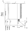
- FIG. 2 is a graphical representation 90 of the voltage 92 at node 32 and the current 94 through the injector 12 driven by a prior art injector driver.
- the initiation of an injector command 96 is coincident with the initiation of a peak mode phase 98 and causes the current 94 through the injector 12 to rise to a desired peak current 100 in approximately 330 ⁇ s.
- a hold mode phase 102 begins and stays active until the end of the injector command 96.
- the injector current 94 is lower than during the peak mode 98, but at a level to hold the armature in the solenoid in the injector 12 in the fuel delivery position after the peak mode 98 operation has caused the injector current 94 to rise high enough to move the solenoid armature into the fuel delivery position.
- Transistor 22 would be selectively enabled to increase the current through the injector 12 and would be disabled to allow the injector 12 current to fall, and transistor 34 would be on throughout the duration of the injector command 96.
- the current through the injector 12 would be sensed by the current sensing resistor 38 and amplifier 40.
- transistor 22 When a predetermined peak current is detected, during both the peak mode 98 and the hold mode 102, transistor 22 would be turned off and the current through the injector 12 would be routed through the diode 30 and the transistor 34 to thereby effectively short circuit the terminals of the injector 12.
- the injector current 94 would have decayed to a predetermined lower current, the transistor 22 would be enabled again.
- FIG. 3 is a graphical representation 110 of the voltage 112 at node 32 and the current 114 through the injector 12 using the driver circuit 10 of FIG. 1 in a first method of operation according to the present invention.
- a charge mode phase 116 is initiated.
- transistors 22 and 54 remain conductive and transistor 34 is initially conductive to allow current to build up in the injector 12.
- transistor 34 When a pre-determined peak current 117 is detected using the current sensing resistor 38 and voltage amplifier 40, transistor 34 is turned off and the flyback energy from the injector 12 is captured by the storage capacitor 52 with the injector 12 current flowing through the diode 46, storage capacitor 52, transistor 54, and charge current sensing resistor 56. Once the current through the charge current sensing resistor 56 has dropped to a second lower level 120, transistor 34 is turned back on and the cycle is repeated.
- the RMS current 118 during the charge mode 116 is less than the current necessary to move the pintle or armature in the solenoid of the injector 12. This method essentially uses the injector 12 in a voltage boost mode configuration.
- Zener diode 78 determines the upper limit of the voltage on node 32 to avoid overstressing the transistor 34. This upper limit in the preferred embodiment is about 50 volts.
- the duration of the charge mode 116 is usually set to last a predetermined time, with the peak mode phase 98 and a current boost mode phase 126 beginning at the termination of the charge mode 116, the voltage amplifier 62 can be used to terminate the charge mode operation once a desired voltage at node 50 has been reached. If the charge mode 116 duration is determined by the output of the voltage amplifier 62, the peak mode 98 and boost mode 126 could be delayed in order to deliver fuel to the engine at the proper time.
- transistors 22, 34, 54, and 70 are conductive to apply the voltage present at node 50 (approximately 50 volts in the preferred embodiment) across the injector 12. Placing this capacitor voltage across the injector 12 sharply decreases the rise time in the peak mode phase 98 of operation from approximately the 336 ⁇ s of FIG. 2 to approximately 104 ⁇ s as shown in FIG. 3.
- the transistors 70 and 54 are turned off. The operation of the circuit 10 after the end of the boost mode phase 126 is the same as the operation of the circuit 10 described above with respect to FIG. 2.
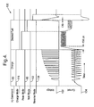
- FIG. 4 is a graphical representation 130 of the voltage 132 at node 32 and the current 134 through the injector 12 using the driver circuit of FIG. 1 in a second method of operation according to the present invention.
- the second method differs from the first method of FIG. 3 in that the charge built up on the storage capacitor 52 is not applied to the injector 12 at the beginning of the peak mode 98, but rather the voltage on the storage capacitor 52 is applied shortly after the end of the injector command 96 in a direction to reverse the voltage across the injector 12 and quickly collapse the magnetic field and eddy currents in the injector 12. This results in improved injector closing response.
- the charge mode 116 is the same as described above for FIG. 3, and the peak mode 98 and hold mode 102 are the same as described above for FIG. 2.
- a delay 136 is provided to allow the injector current 134 to decay to zero amps when the flyback voltage across the injector 12 quickly reduces the injector current 134.
- a reverse mode phase 138 begins by enabling transistors 48, 28 and 54 to apply the reverse voltage to the injector 12.
- the duration of the reverse mode 138 is a predetermined time.
- the rise time of the injector current 134 is improved from 336 ⁇ s of FIG. 2 to 156 ⁇ s in FIG. 4 due to the reduction in the eddy currents in the injector 12 during the charge mode 116. This reduction is most beneficial if the peak mode 98 begins at the end of the charge mode 116.
- FIG. 5 is FIG. 1 with the addition of an external voltage supply 142.
- the external voltage supply 142 is applied to node 50 through the anode-to-cathode junction of a diode 76.
- the transistor 54 is conductive in this third method of operation and the storage capacitor 52 operates as a voltage stabilizing capacitor.
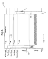
- FIG. 6 is a graphical representation 150 of the voltage 152 at node 32 and the current 154 through the injector 12 using the driver circuit of FIG. 5 in a third method of operation according to the present invention.
- an external voltage supply 142 is applied to terminal 74. Since the external voltage supply 142 is applied to node 50, there is no need for a charge mode 116, and both the boost mode 126 and reverse mode 138 can be used since external voltage supply 142 does not lose charge as does the storage capacitor 52 when current is drawn from node 50.
- FIG. 7 is the driver circuit 10 of FIG. 1 with the diodes 26 and 30 removed.
- the transistor 28 would then be enabled at the appropriate times to provide a current path to chassis ground when either diode 26 or diode 30 were to be conductive in the operation of the driver circuit 10 of FIG. 1.
Landscapes
- Engineering & Computer Science (AREA)
- Physics & Mathematics (AREA)
- Electromagnetism (AREA)
- Power Engineering (AREA)
- Chemical & Material Sciences (AREA)
- Combustion & Propulsion (AREA)
- Mechanical Engineering (AREA)
- General Engineering & Computer Science (AREA)
- Electrical Control Of Air Or Fuel Supplied To Internal-Combustion Engine (AREA)
- Fuel-Injection Apparatus (AREA)
Applications Claiming Priority (1)
| Application Number | Priority Date | Filing Date | Title |
|---|---|---|---|
| US11/114,594 US7349193B2 (en) | 2005-04-26 | 2005-04-26 | Solenoid driver with high-voltage boost and reverse current capability |
Publications (2)
| Publication Number | Publication Date |
|---|---|
| EP1717824A2 true EP1717824A2 (fr) | 2006-11-02 |
| EP1717824A3 EP1717824A3 (fr) | 2011-09-07 |
Family
ID=36782274
Family Applications (1)
| Application Number | Title | Priority Date | Filing Date |
|---|---|---|---|
| EP06075866A Withdrawn EP1717824A3 (fr) | 2005-04-26 | 2006-04-11 | Contrôleur d'un solénoide |
Country Status (2)
| Country | Link |
|---|---|
| US (1) | US7349193B2 (fr) |
| EP (1) | EP1717824A3 (fr) |
Cited By (3)
| Publication number | Priority date | Publication date | Assignee | Title |
|---|---|---|---|---|
| EP2390488A1 (fr) * | 2010-05-31 | 2011-11-30 | Hitachi Automotive Systems, Ltd. | Contrôleur de moteur à combustion interne |
| EP1489731B1 (fr) * | 2003-06-17 | 2015-09-09 | C.R.F. Società Consortile per Azioni | Circuit pour commander des charges inductives à haute efficacité, en particulier pour actionneurs électriques. |
| EP2286507B1 (fr) * | 2008-05-13 | 2016-07-06 | Automatic Switch Company | Système de commande de solénoïde basse puissance et procédé |
Families Citing this family (11)
| Publication number | Priority date | Publication date | Assignee | Title |
|---|---|---|---|---|
| DE102005019709A1 (de) * | 2005-04-28 | 2006-11-02 | Robert Bosch Gmbh | Endstufe mit Zenerspannungs-Symmetrierung |
| US7537145B2 (en) * | 2007-02-01 | 2009-05-26 | Black & Decker Inc. | Multistage solenoid fastening device |
| DE102008022947B4 (de) * | 2008-05-09 | 2021-11-04 | Vitesco Technologies GmbH | Verfahren und Vorrichtung zur Ansteuerung eines Stellantriebs |
| US20090309054A1 (en) * | 2008-06-11 | 2009-12-17 | Automatic Switch Company | System and method of operating a solenoid valve at minimum power levels |
| US8314606B2 (en) * | 2009-11-17 | 2012-11-20 | Renesas Electronics America Inc. | Current sensing and measuring method and apparatus |
| US9812942B2 (en) | 2012-01-10 | 2017-11-07 | Renesas Electronics America Inc. | Distributed driving system |
| DE102012201254A1 (de) | 2012-01-30 | 2013-08-01 | Robert Bosch Gmbh | Ansteuerschaltung für mindestens zwei elektromagnetische Aktoren von Einspritzventilen |
| DE102013203130A1 (de) * | 2013-02-26 | 2014-08-28 | Robert Bosch Gmbh | Verfahren zur Steuerung eines Einspritzvorgangs eines Magnetinjektors |
| CN103400724B (zh) * | 2013-08-14 | 2015-06-03 | 宁波市镇海华泰电器厂 | 兼具抗雷功能的节电静噪交流接触器 |
| WO2015143109A1 (fr) * | 2014-03-20 | 2015-09-24 | GM Global Technology Operations LLC | Entraînement à courant optimal pour commande d'actionneur |
| FR3094408B1 (fr) * | 2019-03-26 | 2021-03-05 | Continental Automotive | Procédé de commande d’un injecteur de carburant haute pression |
Family Cites Families (10)
| Publication number | Priority date | Publication date | Assignee | Title |
|---|---|---|---|---|
| US3097777A (en) * | 1961-01-09 | 1963-07-16 | Rheem Electronics Corp | Tape handling apparatus |
| IT1261360B (it) * | 1993-11-19 | 1996-05-20 | Fiat Ricerche | Sistema elettronico per il controllo di carichi induttivi di iniettoridi un impianto di alimentazione per motori a combustione interna |
| DE19526681B4 (de) * | 1995-07-21 | 2006-06-22 | Fev Motorentechnik Gmbh | Verfahren zur zeitgenauen Steuerung der Ankerbewegung eines elektromagnetisch betätigbaren Stellmittels |
| US5717562A (en) * | 1996-10-15 | 1998-02-10 | Caterpillar Inc. | Solenoid injector driver circuit |
| DE19732854B4 (de) * | 1997-07-30 | 2006-04-20 | Mitsubishi Denki K.K. | Steuervorrichtung zum Steuern einer Kraftstoffeinspritzvorrichtung einer Brennkraftmaschine |
| DE19921938A1 (de) * | 1998-06-15 | 1999-12-16 | Fev Motorentech Gmbh | Verfahren zur Erhöhung der Abwurfgeschwindigkeit des Ankers an einer elektromagnetisch betätigbaren Stelleinrichtung |
| DE19833830A1 (de) * | 1998-07-28 | 2000-02-03 | Bosch Gmbh Robert | Verfahren und Vorrichtung zur Steuerung wenigstens eines Magnetventils |
| US6175484B1 (en) * | 1999-03-01 | 2001-01-16 | Caterpillar Inc. | Energy recovery circuit configuration for solenoid injector driver circuits |
| ITTO20030452A1 (it) * | 2003-06-17 | 2004-12-18 | Fiat Ricerche | Circuito di controllo per il pilotaggio ad alta efficienza |
| ITTO20030609A1 (it) * | 2003-08-05 | 2005-02-06 | Fiat Ricerche | Metodo di funzionamento di un dispositivo di comando di elettroattuatori induttivi. |
-
2005
- 2005-04-26 US US11/114,594 patent/US7349193B2/en not_active Expired - Lifetime
-
2006
- 2006-04-11 EP EP06075866A patent/EP1717824A3/fr not_active Withdrawn
Cited By (7)
| Publication number | Priority date | Publication date | Assignee | Title |
|---|---|---|---|---|
| EP1489731B1 (fr) * | 2003-06-17 | 2015-09-09 | C.R.F. Società Consortile per Azioni | Circuit pour commander des charges inductives à haute efficacité, en particulier pour actionneurs électriques. |
| EP2286507B1 (fr) * | 2008-05-13 | 2016-07-06 | Automatic Switch Company | Système de commande de solénoïde basse puissance et procédé |
| EP2390488A1 (fr) * | 2010-05-31 | 2011-11-30 | Hitachi Automotive Systems, Ltd. | Contrôleur de moteur à combustion interne |
| CN102278219A (zh) * | 2010-05-31 | 2011-12-14 | 日立汽车系统株式会社 | 内燃机控制装置 |
| CN104018948A (zh) * | 2010-05-31 | 2014-09-03 | 日立汽车系统株式会社 | 内燃机控制装置 |
| US8978625B2 (en) | 2010-05-31 | 2015-03-17 | Hitachi Automotive Systems, Ltd. | Internal combustion engine controller |
| CN104018948B (zh) * | 2010-05-31 | 2016-01-20 | 日立汽车系统株式会社 | 内燃机控制装置 |
Also Published As
| Publication number | Publication date |
|---|---|
| US20060238949A1 (en) | 2006-10-26 |
| US7349193B2 (en) | 2008-03-25 |
| EP1717824A3 (fr) | 2011-09-07 |
Similar Documents
| Publication | Publication Date | Title |
|---|---|---|
| CN101230808B (zh) | 内燃机控制装置 | |
| US7349193B2 (en) | Solenoid driver with high-voltage boost and reverse current capability | |
| US5975057A (en) | Fuel injector control circuit and system with boost and battery switching, and method therefor | |
| US8514541B2 (en) | Injector drive circuit | |
| US7057870B2 (en) | Inductive load driver circuit and system | |
| CN104806369B (zh) | 高压共轨柴油发动机喷油器多脉冲喷射控制方法 | |
| JP5140762B2 (ja) | 噴射バルブを駆動制御するための回路装置 | |
| US6766788B2 (en) | Pre-charging strategy for fuel injector fast opening | |
| US20190170078A1 (en) | Injection controller | |
| US11486511B2 (en) | Electromagnetic valve drive device | |
| CN104747332B (zh) | 一种柴油机电控共轨喷油器的驱动电路 | |
| US4770178A (en) | Method and circuit arrangement for controlling an injection valve | |
| US7301256B2 (en) | Method and circuit configuration for operating a piezoelectric actuator | |
| JP2021113538A (ja) | 電磁弁駆動装置 | |
| JPH0758898B2 (ja) | 電磁負荷の高速切替装置 | |
| JP2018096229A (ja) | 噴射制御装置 | |
| US7598732B2 (en) | Circuit and method for generating a current pulse in a waveguide | |
| JP7135809B2 (ja) | 噴射制御装置 | |
| CN111322165A (zh) | 燃料喷射阀驱动装置 | |
| JP2014118860A (ja) | 電磁弁駆動装置 | |
| JP2020188374A (ja) | 電磁弁駆動装置 | |
| CN104373662A (zh) | 控制电磁阀的方法和装置 | |
| JP6575333B2 (ja) | 燃料噴射制御装置 | |
| US20110273220A1 (en) | Optimal mosfet driver circuit for reducing electromagnetic interference and noise | |
| EP1669577B1 (fr) | Circuit de commande pour charge inductive avec détection de surintensité |
Legal Events
| Date | Code | Title | Description |
|---|---|---|---|
| PUAI | Public reference made under article 153(3) epc to a published international application that has entered the european phase |
Free format text: ORIGINAL CODE: 0009012 |
|
| AK | Designated contracting states |
Kind code of ref document: A2 Designated state(s): AT BE BG CH CY CZ DE DK EE ES FI FR GB GR HU IE IS IT LI LT LU LV MC NL PL PT RO SE SI SK TR |
|
| AX | Request for extension of the european patent |
Extension state: AL BA HR MK YU |
|
| PUAL | Search report despatched |
Free format text: ORIGINAL CODE: 0009013 |
|
| AK | Designated contracting states |
Kind code of ref document: A3 Designated state(s): AT BE BG CH CY CZ DE DK EE ES FI FR GB GR HU IE IS IT LI LT LU LV MC NL PL PT RO SE SI SK TR |
|
| AX | Request for extension of the european patent |
Extension state: AL BA HR MK YU |
|
| RIC1 | Information provided on ipc code assigned before grant |
Ipc: H01F 7/06 20060101AFI20110803BHEP |
|
| AKY | No designation fees paid | ||
| REG | Reference to a national code |
Ref country code: DE Ref legal event code: R108 Effective date: 20120516 |
|
| STAA | Information on the status of an ep patent application or granted ep patent |
Free format text: STATUS: THE APPLICATION IS DEEMED TO BE WITHDRAWN |
|
| 18D | Application deemed to be withdrawn |
Effective date: 20120308 |