EP1717911A2 - Luminaire, dispositif de contrôle, barre omnibus, disposition de circuit et adaptateur à un bar omnibus - Google Patents
Luminaire, dispositif de contrôle, barre omnibus, disposition de circuit et adaptateur à un bar omnibus Download PDFInfo
- Publication number
- EP1717911A2 EP1717911A2 EP06007916A EP06007916A EP1717911A2 EP 1717911 A2 EP1717911 A2 EP 1717911A2 EP 06007916 A EP06007916 A EP 06007916A EP 06007916 A EP06007916 A EP 06007916A EP 1717911 A2 EP1717911 A2 EP 1717911A2
- Authority
- EP
- European Patent Office
- Prior art keywords
- busbar
- fuse
- luminaire
- voltage
- operating device
- Prior art date
- Legal status (The legal status is an assumption and is not a legal conclusion. Google has not performed a legal analysis and makes no representation as to the accuracy of the status listed.)
- Granted
Links
- 239000004020 conductor Substances 0.000 claims description 82
- 210000002105 tongue Anatomy 0.000 claims description 26
- 230000007935 neutral effect Effects 0.000 claims description 12
- 230000001960 triggered effect Effects 0.000 claims description 8
- 230000008878 coupling Effects 0.000 abstract description 3
- 238000010168 coupling process Methods 0.000 abstract description 3
- 238000005859 coupling reaction Methods 0.000 abstract description 3
- 238000003780 insertion Methods 0.000 description 8
- 230000037431 insertion Effects 0.000 description 8
- 238000005192 partition Methods 0.000 description 5
- 238000010276 construction Methods 0.000 description 4
- 238000009434 installation Methods 0.000 description 4
- 230000005540 biological transmission Effects 0.000 description 3
- 230000013011 mating Effects 0.000 description 3
- 238000011144 upstream manufacturing Methods 0.000 description 3
- RYGMFSIKBFXOCR-UHFFFAOYSA-N Copper Chemical compound [Cu] RYGMFSIKBFXOCR-UHFFFAOYSA-N 0.000 description 2
- VYPSYNLAJGMNEJ-UHFFFAOYSA-N Silicium dioxide Chemical compound O=[Si]=O VYPSYNLAJGMNEJ-UHFFFAOYSA-N 0.000 description 2
- 229910052802 copper Inorganic materials 0.000 description 2
- 239000010949 copper Substances 0.000 description 2
- 238000010586 diagram Methods 0.000 description 2
- 239000012777 electrically insulating material Substances 0.000 description 2
- 239000003550 marker Substances 0.000 description 2
- 238000002844 melting Methods 0.000 description 2
- 230000008018 melting Effects 0.000 description 2
- 229910052751 metal Inorganic materials 0.000 description 2
- 239000002184 metal Substances 0.000 description 2
- UKGJZDSUJSPAJL-YPUOHESYSA-N (e)-n-[(1r)-1-[3,5-difluoro-4-(methanesulfonamido)phenyl]ethyl]-3-[2-propyl-6-(trifluoromethyl)pyridin-3-yl]prop-2-enamide Chemical compound CCCC1=NC(C(F)(F)F)=CC=C1\C=C\C(=O)N[C@H](C)C1=CC(F)=C(NS(C)(=O)=O)C(F)=C1 UKGJZDSUJSPAJL-YPUOHESYSA-N 0.000 description 1
- 230000002411 adverse Effects 0.000 description 1
- 229910052782 aluminium Inorganic materials 0.000 description 1
- XAGFODPZIPBFFR-UHFFFAOYSA-N aluminium Chemical compound [Al] XAGFODPZIPBFFR-UHFFFAOYSA-N 0.000 description 1
- 230000004323 axial length Effects 0.000 description 1
- 238000005452 bending Methods 0.000 description 1
- 230000002457 bidirectional effect Effects 0.000 description 1
- 230000000903 blocking effect Effects 0.000 description 1
- 230000015556 catabolic process Effects 0.000 description 1
- 239000003795 chemical substances by application Substances 0.000 description 1
- 230000001066 destructive effect Effects 0.000 description 1
- 238000001514 detection method Methods 0.000 description 1
- 238000004870 electrical engineering Methods 0.000 description 1
- 230000005611 electricity Effects 0.000 description 1
- 238000010438 heat treatment Methods 0.000 description 1
- 238000002347 injection Methods 0.000 description 1
- 239000007924 injection Substances 0.000 description 1
- 238000009413 insulation Methods 0.000 description 1
- 239000000155 melt Substances 0.000 description 1
- 239000002244 precipitate Substances 0.000 description 1
- 238000004886 process control Methods 0.000 description 1
- 230000005855 radiation Effects 0.000 description 1
- 238000010079 rubber tapping Methods 0.000 description 1
- 239000004576 sand Substances 0.000 description 1
Images




Classifications
-
- H—ELECTRICITY
- H01—ELECTRIC ELEMENTS
- H01R—ELECTRICALLY-CONDUCTIVE CONNECTIONS; STRUCTURAL ASSOCIATIONS OF A PLURALITY OF MUTUALLY-INSULATED ELECTRICAL CONNECTING ELEMENTS; COUPLING DEVICES; CURRENT COLLECTORS
- H01R33/00—Coupling devices specially adapted for supporting apparatus and having one part acting as a holder providing support and electrical connection via a counterpart which is structurally associated with the apparatus, e.g. lamp holders; Separate parts thereof
- H01R33/945—Holders with built-in electrical component
- H01R33/955—Holders with built-in electrical component with switch operated manually and independent of engagement or disengagement of coupling
-
- H—ELECTRICITY
- H01—ELECTRIC ELEMENTS
- H01R—ELECTRICALLY-CONDUCTIVE CONNECTIONS; STRUCTURAL ASSOCIATIONS OF A PLURALITY OF MUTUALLY-INSULATED ELECTRICAL CONNECTING ELEMENTS; COUPLING DEVICES; CURRENT COLLECTORS
- H01R25/00—Coupling parts adapted for simultaneous co-operation with two or more identical counterparts, e.g. for distributing energy to two or more circuits
- H01R25/14—Rails or bus-bars constructed so that the counterparts can be connected thereto at any point along their length
-
- H—ELECTRICITY
- H01—ELECTRIC ELEMENTS
- H01R—ELECTRICALLY-CONDUCTIVE CONNECTIONS; STRUCTURAL ASSOCIATIONS OF A PLURALITY OF MUTUALLY-INSULATED ELECTRICAL CONNECTING ELEMENTS; COUPLING DEVICES; CURRENT COLLECTORS
- H01R25/00—Coupling parts adapted for simultaneous co-operation with two or more identical counterparts, e.g. for distributing energy to two or more circuits
- H01R25/14—Rails or bus-bars constructed so that the counterparts can be connected thereto at any point along their length
- H01R25/142—Their counterparts
-
- H—ELECTRICITY
- H01—ELECTRIC ELEMENTS
- H01R—ELECTRICALLY-CONDUCTIVE CONNECTIONS; STRUCTURAL ASSOCIATIONS OF A PLURALITY OF MUTUALLY-INSULATED ELECTRICAL CONNECTING ELEMENTS; COUPLING DEVICES; CURRENT COLLECTORS
- H01R33/00—Coupling devices specially adapted for supporting apparatus and having one part acting as a holder providing support and electrical connection via a counterpart which is structurally associated with the apparatus, e.g. lamp holders; Separate parts thereof
- H01R33/945—Holders with built-in electrical component
-
- H—ELECTRICITY
- H01—ELECTRIC ELEMENTS
- H01R—ELECTRICALLY-CONDUCTIVE CONNECTIONS; STRUCTURAL ASSOCIATIONS OF A PLURALITY OF MUTUALLY-INSULATED ELECTRICAL CONNECTING ELEMENTS; COUPLING DEVICES; CURRENT COLLECTORS
- H01R33/00—Coupling devices specially adapted for supporting apparatus and having one part acting as a holder providing support and electrical connection via a counterpart which is structurally associated with the apparatus, e.g. lamp holders; Separate parts thereof
- H01R33/945—Holders with built-in electrical component
- H01R33/95—Holders with built-in electrical component with fuse; with thermal switch
-
- H—ELECTRICITY
- H01—ELECTRIC ELEMENTS
- H01R—ELECTRICALLY-CONDUCTIVE CONNECTIONS; STRUCTURAL ASSOCIATIONS OF A PLURALITY OF MUTUALLY-INSULATED ELECTRICAL CONNECTING ELEMENTS; COUPLING DEVICES; CURRENT COLLECTORS
- H01R13/00—Details of coupling devices of the kinds covered by groups H01R12/70 or H01R24/00 - H01R33/00
- H01R13/44—Means for preventing access to live contacts
- H01R13/447—Shutter or cover plate
Definitions
- the invention initially relates to a luminaire according to the preamble of claim 1.
- Such lights are known and widely used. They have also been manufactured by the Applicant for decades.
- the bulbs are connected to power supply lines that provide the supply or operating voltage for the bulbs.
- the lamp has three electronic ballasts, so that the three bulbs are individually controlled.
- the ballast may for example be a working according to the DALI protocol ballast, which is individually addressable and connected to a signal line.
- the luminaire can be integrated into a network of luminaires and receive control information via the signal line via a central control. For example, the information may be transmitted from the central controller to one of the lamps of the luminaire to enter a certain dimming state, e.g. also for the purpose of color mixing, to flash, to turn on, to turn off or the like.
- the power supply line which usually includes a phase conductor and a neutral conductor, is typically connected to the luminaire via a first connection and transmits, for example, an operating voltage AC of 230 V or 110 V.
- a second connection For connecting the signal line to the luminaire or to the Luminaire associated operating device, so for example the electronic ballast, a second connection provided.
- the signal line is typically one two-core cable, via which voltages up to 25 V, for example, are transmitted.
- the signal line is normally laid separately from the power supply lines.
- the object of the invention is to provide a lamp that offers greater security against assembly errors.
- the invention solves this problem with the features of claim 1, in particular with those of the characterizing part, and is accordingly characterized in that the second connection is associated with a fuse against overvoltage, which is formed exchangeable or switchable.
- the principle of the invention thus consists essentially in providing a fuse which can be triggered when a nominal voltage is exceeded. If there is a faulty mounting, that is to say a faulty connection of the lines, so that the significantly higher operating voltage is inadvertently applied to the second connection for the signal line, the fuse can be tripped. If the fuse is advantageously designed as a fuse, the melted thread can melt as a result of heating and thus protect the downstream of the fuse arranged light or the operating device of the lamp and the electronics located there against overvoltage by interrupting the circuit.
- the fuse is interchangeable in the event of destructive tripping, such as a fuse.
- a fuse is advantageously arranged at an easily accessible location of the lamp and can be supported, for example, by conventional spring clips and replaced after release by a new fuse.
- the fuse may also be designed to be switchable, so that it triggers automatically upon detection of a nominal voltage exceeding overvoltage, and subsequently either manually switched from its tripped, the power line interrupting state in a current-conducting state or automatically switches back, for example, after a certain period of time.
- the fuse triggers very quickly and safely and permanently disconnects even high voltages of up to 400 V in the tripped state.
- This high breakdown strength of the tripped fuse is required in the event that instead of two signal lines, two phase conductors of different potential are connected to the second terminal.
- the fuse when the lamp is to be connected to a power rail.
- the fuse can safely trip in the event of faulty mounting and a faulty assignment of the conductor in the busbar and protect the lamp or the operating device of the lamp.
- the arrangement of the replaceable fuse or a manually switchable fuse in an easily accessible place mean that only a housing part of the lamp or an operating device of the lamp must be removed, wherein After removal of the housing part, for example, a mounting device for the fuse is accessible, so that the fuse can be removed and replaced by a new fuse.
- the lamp is associated with a control gear on which the first and / or the second terminal is arranged.
- the operating device of the lamp for example, an electronic ballast, a transformer or another
- the lamp directly associated device is referred to, with which the function of the lamp is controlled.
- the operating device is typically arranged directly next to the luminaire and may be located, for example, in the housing of the luminaire or in a separate operating device housing. In the event that the lamp is connected via a busbar adapter to the busbar, the operating device may also be located within a housing of the busbar adapter.
- two inputs for signal lines are assigned to the second terminal, which are short-circuited with each other via an electronic component, in particular via a varistor, that causes a large current flow through the fuse when a desired voltage between the two inputs is exceeded becomes. This current flow can trigger the fuse.
- the electronic component While at lower voltages, so in the case of a proper connection, the electronic component practically does not appear, for example, because its electrical resistance is very high, so that flows through the electronic component normally no current, can exceed a target voltage , namely, in the case of a faulty mounting, through the electronic component through a current flow, because due to the large voltage, for example, above a threshold voltage of 60 V, the electrical resistance through the Component through reduced.
- a target voltage namely, in the case of a faulty mounting
- Such a per se known device is for example a varistor (variable resistor).
- the fuse is triggered only above a voltage of 30 V or 50 V, in particular above 230 V, further in particular above 300V.
- This embodiment of the invention initially takes into account that the control information transmitted via the signal line as signals typically have only lower voltages of less than 30 V, but in any case of less than 230 V.
- voltage amplitudes of more than 400 V may occur, so that the fuse and the varistor must be designed accordingly.
- the voltage above which the fuse is triggered should, according to the invention, be selected such that it exceeds the voltage used to transmit the control information plus a certain surcharge to compensate for tolerances, for example, on the order of a few volts or a few tens of volts.
- control information corresponds to the DALI protocol (Digital Addressable Lighting Interface).
- DALI Digital Addressable Lighting Interface
- This protocol which was developed by the DALI working group at the Central Association of the German Electrical Engineering and Electronics Industry (ZVEI), is, for example, described in detail in the pre-published Handbook DALI of DALI AG, 2nd edition, 2001, publisher Richard Pflaum Verlag Münch en, described.
- the invention further relates to an operating device for a luminaire, in particular an electronic ballast, according to the preamble of claim 6.
- Such an operating device may be part of a lamp or separately from the lamp, preferably immediately adjacent to the lamp, arranged.
- electronic ballasts are also other devices for a lamp as operating equipment into consideration, with which the lamp can be dimmed, switched on or off or with which the radiation behavior or the color of the lamp can be influenced in any other way or a light source of the lamp can be addressed ,
- a control gear of the prior art typically has a first terminal for connection to a power supply line, with which the supply voltage for the operation of a light source of the lamp is transmitted.
- the operating device furthermore has a second connection for a signal line, with which control information for controlling the luminaire is transmitted.
- the control information may be formed, for example, according to the DALI protocol.
- An output of the operating device is typically connected to the lighting means, so that depending on the control information or control commands received, the operating device can perform a corresponding control of the lighting means or of the lighting means.
- the object of the invention is to develop the well-known by public prior use operating device of the preamble of claim 6 such that a greater security against assembly errors is achieved.
- the invention solves this problem with the features of claim 6, in particular with those of the characterizing part, and is accordingly characterized in that the second terminal is associated with a fuse against overvoltage, which is formed exchangeable or switchable.
- the fuse corresponds to the fuse previously described in connection with a lamp. This is again designed exchangeable or switchable.
- the fuse can be incorporated directly into the operating device or upstream of the operating device.
- the invention relates to a busbar according to the preamble of claim 10.
- Such a busbar is for example from the DE 100 25 646 A1 known.
- the known busbar has power supply lines (standard phases 1, 2 and 3), ie phase conductors, which serve to supply a lamp with operating voltage.
- the known busbar and control lines which can serve for light control and thus represent signal lines in the sense of the preamble of claim 10, can be passed through the control information to the light.
- the luminaire has a first connection, via which it can be connected to the phase conductor of the busbar, and via at least one second connection, by means of which it can be connected to the signal line of the busbar.
- the two connections on the luminaire correspond to tapping points in the conductor rails of the busbar.
- the luminaire may in turn have an operating device which, as a result of receiving control information, can control the luminous means accordingly.
- the operating device may also only be associated with the two terminals of the luminaire.
- the object of the invention is to further develop a busbar according to the preamble of claim 10 such that it better protects the lamp or a control gear for the lamp against consequences of incorrect installation or misconnection to the busbar.
- the invention solves this problem with the features of claim 10, in particular with those of the characterizing part, and is accordingly characterized in that the second terminal is assigned a fuse against overvoltage, which is designed to be interchangeable or switchable.
- An essential advantage of the busbar according to the invention is that a conventional busbar, which has, for example, three phase conductors and a neutral conductor, now also a luminaire, which receives control information via a signal line, can be connected without causing assembly errors serious consequences.
- the arrangement of a fuse against overvoltage which is designed to be interchangeable or switchable, allows protection of the high-quality equipment or the lamp in the event of overvoltage due to a mounting error. By replacing the fuse or by switching back the fuse from the tripped state in a state of rest in which it passes, the operability of the lamp or the operating device can be restored after a great effort to correct installation.
- the fuse can be arranged, for example, on the busbar or od directly or indirectly fixed to an adapter. The like. Be arranged, which is attached to the power rail.
- the invention further relates to a circuit arrangement according to the preamble of claim 14.
- the object of this invention is a circuit arrangement for a lamp or for a control gear or to design for a busbar less prone to incorrect assembly.
- the invention solves this problem with the features of claim 14, in particular with those of the characterizing part, and is accordingly characterized in that the second connection is associated with a fuse against overvoltage, which is formed exchangeable or switchable.
- the circuit arrangement according to the invention can also be produced separately from a luminaire or an operating device or a busbar and connected as a separate component to a lamp or to a control gear or to a power rail.
- the invention further relates to a busbar according to the preamble of claim 18.
- the known busbar is manufactured, for example, under the name 3-phase busbar for decades by the applicant. It typically comprises three phase conductors and a neutral conductor, via which one or more lamps can be supplied with operating voltage.
- a busbar adapter is typically used in the formed in the manner of a U-profile busbar and mechanically and electrically locked to the busbar.
- the different phase conductors can optionally be contacted to the lamp, for example to connect to a group of luminaires, which can be controlled as lighting group.
- the object of the invention is to develop the known busbar such that the control of the lights is simplified.
- the invention solves this problem with the features of claim 18, in particular with those of the characterizing part, and is accordingly characterized in that a circuit is provided which is one of the two. Conductor as signal line for supplying the luminaire with control information switches.
- the principle of the invention consists essentially in a conventional busbar, e.g. a 3-phase busbar to be connected by a circuit such that one or more of the existing conductors, preferably two conductors, are used in a conventional manner to power the luminaire, wherein at least one, advantageously two, of the existing conductors, in a novel way Signal line to supply the lamp with control information can be used.
- a conventional busbar e.g. a 3-phase busbar to be connected by a circuit such that one or more of the existing conductors, preferably two conductors, are used in a conventional manner to power the luminaire, wherein at least one, advantageously two, of the existing conductors, in a novel way Signal line to supply the lamp with control information can be used.
- the newly provided circuit may preferably comprise a circuit part connecting one end of the bus bar to a central controller for a network of lights.
- the invention makes it possible to use existing busbar systems, which need only be connected in a different way than the conventional one, the busbar not having three phase conductors and a neutral, but a neutral conductor, a phase conductor and a control unit of the DALI network or another Network is connected.
- a marking element is arranged on the busbar, which indicates that one of the conductors is used for the transmission of control information.
- the marking element can further advantageously be detachably fastened to the busbar, so that it can be used as an additional element or accessory. Further advantageously, the marking element is clipped to the busbar, so that without special aids a mounting of the marking element can be made on the busbar.
- the invention relates to a busbar adapter according to the preamble of claim 25.
- busbar adapter is for example from the DE 103 12 012 A1 the applicant, to which reference is made for the purpose of avoiding repetition hereof and the content of which is hereby included for the purpose of recourse to individual features or groups of features in the content of the present patent application.
- the known busbar adapter serves for the mechanical and electrical connection of a lamp with a busbar.
- the adapter if an operating device is present, and the mechanical and electrical connection of the operating device, and possibly also at the same time also serve the light with the busbar.
- the housing of the busbar adapter can also be incorporated, for example, the operating device with.
- the known busbar adapter of the applicant comes in an advantageous manner already with a very small number of components and allows a particularly simple installation.
- the known busbar adapter has for this purpose a first and a second switching shaft, on the one hand via a phase conductor contact tongue and on the other hand have a neutral contact tongue, with which the conductor rails in the busbar are contacted.
- the object of this invention is to develop a busbar adapter according to the preamble of claim 1 such that in a simple design, a light having a first terminal for connection to a power supply line and a second terminal for connection a signal line, with the busbar is connectable.
- each switching shaft has two rotatably connected to the switching shaft contact elements.
- the principle of the invention consists essentially in assigning two switching elements each two contact elements. All contact elements can be accommodated by skillful arrangement despite the very tight space in the switching shafts.
- Each contact element has a plug-in element, preferably a tongue.
- the plug element can be connected to a connection conductor which has a mating plug element.
- the mating plug element may for example be a flat plug sleeve.
- the plug element preferably each plug element, is arranged in the vicinity of the pivot axis of the switching shaft.
- each switching shaft is assigned in each case two contact elements, the conventional construction of the in the DE 103 12 012 A1 recourse to the adapter described.
- Each switching shaft has an axis of rotation, which is aligned in the assembled state substantially perpendicular to the longitudinal extent of the busbar.
- the actuating surfaces for carrying out a rotational movement of the respective shift shaft are accordingly located outside the interior of the bus bar and allow a comfortable attack by a user, with the ability to transmit large torques.
- the Actuating surfaces arranged on a widened axial portion of the respective shift shaft or on a separate operating lever.
- the busbar adapter has a common outlet for all four or more connection conductors.
- a switching shaft on which two contact elements are arranged, has a passage for at least two further connecting conductors, wherein these two connecting conductors contact the plug-in elements of the contact elements of the respective other switching shaft.
- the plug-in elements of a switching shaft for example the switching shaft, which has the contact elements for contacting the signal lines, executed in the assembled state of the bus bar adapter to the bottom of the busbar are, whereas the plug-in elements of the contact elements of the other switching shaft are directed away from the bottom of the busbar.
- the mounting of the busbar adapter can be done in a simple manner.
- the busbar adapter can be manufactured with only a very small number of components.
- the fact that an arrangement of two contact elements on a switching shaft is possible despite the tight contact conditions in the switching shaft due to the predetermined by the insertion slot in the busbar dimensions is surprising.
- the two contact elements are each separated by a plastic or other electrically insulating material.
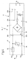
- the luminaire 10 comprises in a conventional construction a housing 11, in the interior 12 of which a luminous means 13 is fixedly arranged.
- the light source for example an incandescent lamp
- the leads connect the lighting means 13 with a schematically indicated operating device 15 for the lighting means, for example in the manner of an electronic ballast.
- the electronic ballast 15 has, in addition to the output 16 for connecting the supply lines 14a and 14b, a first connection 17 for connection to power supply lines 19a and 19b and a second connection 18 for connecting the operating device 15 and thus the light 10 with signal lines 20a and 20b.
- the second terminal 18 thus belongs both to the operating device 15 and to the lamp 10.
- Fig. 3 lamp corresponds to the basic structure of the prior art, however, contains a replaceable fuse explained below.
- the luminaire 10 according to the invention or the operating device 15 according to the invention can also have a plurality of first connections 17 and a plurality of second connections 18.
- Fig. 4 shows a schematic block diagram of a conventional operating device 15 ', in the manner of an electronic Ballast, which supplemented by an indicated circuit 21 can be used as inventive operating device 15 in the lamp 10 of FIG. 3 application.
- the operating device designated 15 'in FIG. 4 is thus a prior art operating device which has an output 16 for the supply lines 14a, 14b to the lighting device 13, a first connection 17 with two connection points 23a and 23b for connection to the voltage supply lines 19a and 19b and a second terminal 18 'with two connection points 22a and 22b, which serve in the conventional operating device 15' for connection to the signal lines 20a and 20b.
- the connection points 22a, 22b thus represent the inputs of a conventional electronic ballast 15 '.
- the signal lines 20a and 20b are connected in the luminaire 10 according to the invention or in an operating device 15 according to the invention.
- the connection points 24a and 24b only the lower voltage that transmits the control information to.
- the connection points 22a and 22b is correspondingly only the lower voltage.
- connection points 24a and 24b If, as a result of a faulty assembly whose possible occurrence will be discussed below, a higher voltage is applied to the connection points 24a and 24b, for example the operating voltage transmitted by the voltage supply lines 19a and 19b is, for example, equal to e.g. 230 V or in the case of a faulty connection to two phase conductors, a voltage in the order of 400 V, the normally a current flow between the connection points 22a and 22b blocking varistor 26 can switch to a conductive state. Namely, a varistor 26 has the peculiarity that it is not current-conducting below a threshold voltage and becomes current-conducting above a threshold voltage. If the threshold voltage is chosen, e.g.
- the voltage range for transmitting the control information is below the threshold voltage and the voltage range, which is conventionally the voltage supply of the lamp 10, is above the threshold voltage, in the event of a mismatch of the varistor 26 is electrically conductive, so that through the varistor 26 a large Electricity flows. This large current also flows through the fuse 25 and triggers it.
- the fuse 25 is designed as a fuse and has a, for example in a sand-filled quartz glass tube arranged on metal thread, which melts when a threshold current is exceeded and after the melting through the connection points 24b and 22b sure, i. impact resistant, and permanently electrically separated from each other.
- the fuse 25 it is sufficient after correction of the connection of the signal lines 20a, 20b and the Power supply lines 19a, 19b to replace the fuse 25 with a new fuse, without it being necessary to replace the operating device 15 or parts of the electronics 27.
- the varistor 26 may remain in the circuit 21.
- a switchable, not shown fuse can be used instead of a conventional fuse, as it is often used in electrical equipment, and is held for example by means of metal spring legs, so that it can be solved by manual attack.
- a switchable, not shown fuse can be used. This can be formed either manually resettable, so that after triggering the fuse 25 and correcting the connection lines, a user can reset a switch.
- the fuse may also be automatically reset and, for example, after a certain period of time, for example 10 or 20 minutes, return to its conducting state.
- the selected fuse 25 triggers very quickly, so that any damage to the subsequent electronics is prevented.
- fuse 25 is a FF315mA 700 V fuse into consideration.
- the varistor may be, for example, a S05K60 varistor from Siemens.
- the operating device designated 15 'in FIG. 4 may be a conventional DALI ballast which can process control information corresponding to the DALI protocol.
- the circuit 21 with the fuse 25 and the varistor 26 may in this way be connected upstream of the conventional DALI ballast 15 'and, for example, also be connected via plug connections or other electrical connections to the input 18' of the conventional operating device 15 '.
- circuit 21 in an inventive operating device 15.
- Fig. 3 indicates this is and represents the conventional operating device 15 with the second terminal 18 together with the circuit 21 as a unit.
- the second connection 18 of the operating device 15 according to FIGS. 3 and 4 also corresponds to the second connection 18 of the luminaire 10 according to the invention, since the operating device 15 is part of the luminaire 10 or belongs to the luminaire 10.
- an operating device is in addition to an electronic ballast and any other device of a lamp 10 into consideration, which can address at least one lamp 13 and is preferably addressable.
- the fuse 25 and / or the circuit 21 may be arranged separately from an operating device 15 to a lamp 10 and, for example, form a separate component. Alternatively, however, an immediate assignment of the fuse 15 or the circuit 21 in or on the housing of the operating device 15 or in or on the housing of the lamp 10 done. Similarly, the fuse 25 and / or the circuit 21 may be disposed in or on a bus bar adapter described later.
- the operating device 15 typically has a first connection 17 for power supply lines, a second connection 18 for signal lines and an output 16 for connection to at least one light source 13, the control information obtained via the signal lines 20a, 20b addressing the at least one light source , for example, dimming or switching.
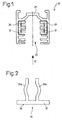
- FIG. 1 can be used in the inventive manner as a busbar for transmitting the operating voltage of a lamp and for transmitting control information.
- the known 3-phase busbar 28 consists of a, in particular made of aluminum, substantially U-shaped profile 29, which has an insertion slot 30 for the head region 72 of a busbar adapter 39 (FIG. 5).
- a busbar 28 and the mechanical and electrical connection with a busbar adapter 39 or with a lamp 10 is hereby on the German patent application DE 103 12 012 A1 the applicant, the content of which is hereby included in the content of the present patent application, also for the purpose of reference to individual features.
- the prior art bus bar 28 includes a neutral and 3-phase conductors.
- a conventional busbar adapter for example according to the DE 103 12 012 A1 , a user can choose to which of the 3-phase conductor the respective lamp is to be connected. In this way, three groups of lights can be fixed to a power rail and controlled in groups in a conventional manner.
- the conventional 3-phase busbar can be switched such that two of the four conductors, eg the conductors 33 and 34, are connected as a signal line can be transmitted via the control information to the light 10.
- the other two conductors 31 and 32 are still used as power supply lines for the luminaire and are respectively switched as a phase conductor and as a neutral. While the power supply lines 31 and 32, thus corresponding to the power supply lines 19a and 19b of FIG. 3, transmit a high operating voltage of, for example, 230V, only the conductors 33 and 34 corresponding to the signal lines 20a and 20b of FIG Control information of a lower voltage, for example 25 V transmitted.
- the circuit according to the invention of the known busbar provides, on the one hand, that the signal lines 33 and 34 of the busbar 28 are connected to a control, not shown, of a network of the luminaires, the control, not shown, coupling the control information to the signal lines 33 and 34. If a bidirectional transmission of control information is provided, the information may also be decoupled from the signal line 33, 34.
- the circuit according to the invention of the known busbar 28 further provides that the lamp 10 to be connected to the busbar 28 and / or an operating device 15 assigned to the luminaire for the luminaire and / or a busbar adapter 39 for connecting the luminaire 10 to the busbar 28 a second terminal 18 or corresponding connection points 24a, 24b provides that can be connected to the conductors 33, 34 of the bus bar 28, being transmitted via this terminal 18 or via these connection points 24a, 24b control information.
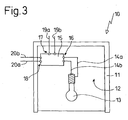
- Fig. 2 shows only schematically indicated a marking element 35 in the manner of a clip, which has a cover plate 37 and two spring legs 36a and 36b.
- the Marking element 35 is inserted in the insertion direction of the arrow E in the receptacle 30 of the bus bar 28 and clipped there, with the insertion of the marking element 35, the two free ends of the spring legs 36a, 36b to move toward each other and slightly after reaching a preferably locked by latching means detent position can expand, so that a secure hold of the marking element 35 is achieved in the busbar 28.
- the cover plate 37 is provided on its underside with a signal surface 38 which may be labeled and may include, for example, a marker indicating that the bus bar 28 is switched to a particular state.
- the marker 35 indicates that the conventional bus bar 28 is in a state where the conductors 33 and 34 are shaded as signal lines due to the circuit of the present invention.
- the user is shown the peeling state of the bus bar 28 in a simple manner, whereby a very simple display option is provided by the clipable design of the marking element 35.
- a user can in this way be informed, by the marking element 35, whether he has received e.g. or not equipped with a DALI ballast can use this luminaire in this busbar.
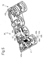
- Fig. 5 shows the busbar adapter according to the invention, which is designated in its entirety by 39, in a perspective view.
- the two housing halves 40a and 40b are unfolded.
- the housing corresponds in terms of its basic structure substantially to the housing of the busbar adapter according to the DE 103 12 012 A1 , the contents of which are hereby included in the content of the present application in order to avoid repetition and for the purpose of reference to individual features.
- the busbar adapter As in the known busbar adapter are in one of the two housing halves, namely in the left with respect to FIG. 5 housing half 40a, two switching shafts 41 and 42 about their respective longitudinal axis, which is indicated in Fig. 6 and designated there with 43 and 44 respectively , rotatably arranged.
- the first shift shaft 41 can be actuated by a manual attack on an operating lever 70
- the second shift shaft 42 can be actuated by attack on a widened, provided with a knurled edge 71 in a simple manner.
- the two housing halves 40a and 40b are pivoted about a film-hinge-like axis against each other and clipped together.
- the flat portion of the busbar adapter 39 designated in FIG. 5 by 72, is inserted into the insertion opening 30 of the busbar 28 according to FIG. 1 for mounting on the busbar 28.
- the first shift shaft 41 can be rotated by 90 °, wherein later to be described contact tongues 73a and 73b, retaining tongues 65a, 65b and an optionally provided Kodierzunge 66 from slots in the half-casings 40a, 40b emerge and into the corresponding grooves in the Busbar can occur.
- the second switching shaft 42 can be pivoted by 90 °, with corresponding contact tongues 73c and 73d emerge from corresponding slots or openings in the housing and the conductors 33, 34 can contact.
- the two switching shafts 41, 42 may, as is also the case with the known busbar adapter, be locked together via a locking arrangement, so that the second switching shaft 42 can only be turned into its contacting state when the first switching shaft 41 is in a contacting state. Under certain circumstances, such an arrangement may also be dispensed with in the busbar adapter according to the invention.
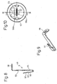
- Fig. 7 indicates in an exploded view that the second Schalfinrelle 42 two contact elements 48 a and 48 b are assigned, which are inserted in the insertion direction x in the hollow switching shaft 42.
- the selector shaft 42 is shown in a longitudinal section in FIG. 11 and comprises a head section 51, an axial section 50 and a foot section 52, which is significantly widened in relation to the head section 51.
- the switching shaft 42 is hollow overall, and includes two chambers 54 a and 54 b, which are separated by a partition 53 from each other.
- the partition wall 53 and the switching shaft 42 are made of an electrically insulating material, preferably made of plastic, and are manufactured as an injection molded part.
- the foot portion 52 has a plate 55 which is provided with two apertures 56a and 56b, so that the switching shaft 42 is provided over its entire axial length with a through opening.
- a to be introduced into the second switching shaft 42 contact element 48 is shown in Fig. 8 in cross section. It comprises a section 58 for forming the contact tongue, which contacts the corresponding conductor rail (eg conductor 33 according to FIG. 1) in the bus bar 28, and that from a central section 59 substantially at right angles is bent.
- An end portion 60 of the contact element is bent over and comprises at its free end a plug-in element 61 in the form of a tongue.
- the plug 61 is slightly offset parallel to the end portion 60.
- a nose 64 are located on the side facing away from the plug 61 side of the central portion 59th
- the two contact elements 48 a, 48 b are electrically separated from each other by the partition 53.
- the connecting conductors for the two contact elements 48a, 48b which are not shown in FIG. 11 and lead to the second terminal 18 of the operating device 15 or the luminaire 10, each have a blade receptacle at its end, which can be connected to the plug 61.
- An assembly of the blade receptacle on the tongue 61 can also be done before the contact element 48 is inserted into the second switching shaft 42. In this case, the contact element 48 and the blade receptacle with the end of the connecting conductor is fastened together on the switching shaft 42.
- the tongue 61 is slightly spaced from the partition wall 53 due to the bend 62, so that there is sufficient space for the flat receptacle, not shown. In principle, this also allows the mounting of the connection conductor with the blade receptacle on the contact element 48 or 48a or 48b, if the contact element is already fixed to the switching shaft 42.
- the tongue 61 extends both substantially along the pivot axis 44 of the second switching shaft 42, and is directed toward the base of the profile 29 of the conductor rail 28 in the assembled state of the contact element 48. A contacting of the tongue 61 through the connecting conductor thus takes place with respect to FIG. 8 from above. This allows, as shown in FIG. 5 only hinted, a supply of the two associated connecting conductors 69c and 69d from above into the switching shaft 42. This leads to a very space-saving overall design of the busbar adapter 39, which is not externally at all from the busbars Adapter of the prior art must be different.
- a cover member 63 is provided which closes the foot portion 52 of the second switching shaft 42 and thus completely covers the contact elements 48a and 48b.
- Fig. 6 shows that the contact elements 45a and 45b are formed substantially at right angles and have at their lower free end in each case a plug-in element 47a and 47b in the manner of a tongue.
- the tongue is used for connection to a mating plug element arranged at one end of a connection conductor 69a, 69b in the manner of a flat plug-in sleeve.
- a contact tongue 73a, 73b which in turn serves for connection to the conductor rails (eg conductors 32 and 31 according to FIG. 1) of the bus bar 28.
- the contact element 45a or 45b corresponds to virtually identical to that in Figures 9 to 12 in the DE 103 12 012 A1 described contact element.
- the attachment of such a contact element 45a and 45b is described in this patent application, so that reference is made to avoid repetition.
- FIG. 5 A special feature of the arrangement is shown in FIG. 5, from which it can be seen that the two connecting conductors 69c and 69d for the second switching shaft 42 are passed through the first switching shaft 41.
- an earth conductor not shown in FIG. 5 can be passed as a further connection conductor through the switching shaft, as shown for example in FIG DE 103 12 012 A1 is shown.
- the first switching shaft 41 is now provided with a first passageway 68a and a second passageway 68b for at least two connection conductors 69c and 69d.
- the connection conductors 69a and 69b associated with the contact elements 45a and 45b leave the foot portion 52 of the first switching shaft 41 together with the connection conductors 69c and 69d, so that the busbar adapter 39 has a common outlet 74 for all four connection conductors, or taking into account a ground conductor, a common outlet for five connection conductors. This common outlet facilitates the connection of the connecting cables with the lamp to be connected to the busbar adapter.
- a partition 46 can be arranged in the interior of the hollow, first control shaft 41. Under certain circumstances, however, these can also be dispensed with if the connecting conductors 69c and 69d are sufficiently insulated and have double insulation, for example.
- the first shift shaft 41 differs from the second shift shaft 42 still by retaining tongues 65a, 65b and a Kodierzunge 66.
- the first shift shaft 41 has a structure which basically in Fig. 8 of DE 103 12 012 A1 shown construction of a switching shaft identical. An additional Kodierzunge 66 is provided, but will not be further discussed in terms of their function at this point.
- contact elements 45a and 45b are inserted into corresponding chambers 67a and 67b in the first shift shaft 41 and can be secured axially by means of corresponding locking lugs 75 (FIG. 6), which engage behind corresponding wall regions 76 of the first shift shaft 41.
- the busbar adapter 39 has on the first switching shaft 41 two contact elements 45a and 45b, which can be brought into contact with the neutral conductor 31 of the busbar 28 and the phase conductor 32 of the busbar.
- the second switching shaft 42 has two contact elements 48 a and 48 b, which can be brought into contact with the signal lines 33, 34 of the bus bar 28. In this way, a lamp 10 can be connected as shown in FIG. 3 with a single busbar adapter 39 to the bus bar 28.
- the contact tongue 73a thus corresponds, for example, to a neutral contact tongue
- the contact tongue 73b corresponds to a phase conductor contact tongue
- the contact tongues 73c and 73d correspond to the signal line contact tongues.
Landscapes
- Circuit Arrangement For Electric Light Sources In General (AREA)
- Details Of Connecting Devices For Male And Female Coupling (AREA)
Applications Claiming Priority (1)
| Application Number | Priority Date | Filing Date | Title |
|---|---|---|---|
| DE102005019632A DE102005019632A1 (de) | 2005-04-26 | 2005-04-26 | Leuchte, Betriebsgerät, Stromschiene, Schaltungsanordnung und Stromschienen-Adapter |
Publications (3)
| Publication Number | Publication Date |
|---|---|
| EP1717911A2 true EP1717911A2 (fr) | 2006-11-02 |
| EP1717911A3 EP1717911A3 (fr) | 2009-07-22 |
| EP1717911B1 EP1717911B1 (fr) | 2012-07-25 |
Family
ID=36859713
Family Applications (1)
| Application Number | Title | Priority Date | Filing Date |
|---|---|---|---|
| EP06007916A Expired - Lifetime EP1717911B1 (fr) | 2005-04-26 | 2006-04-14 | Luminaire |
Country Status (3)
| Country | Link |
|---|---|
| US (1) | US7320610B2 (fr) |
| EP (1) | EP1717911B1 (fr) |
| DE (1) | DE102005019632A1 (fr) |
Cited By (2)
| Publication number | Priority date | Publication date | Assignee | Title |
|---|---|---|---|---|
| WO2014083475A3 (fr) * | 2012-11-30 | 2014-11-06 | Koninklijke Philips N.V. | Dispositif de pilotage pour piloter une charge et dispositif de connecteur pour fournir une puissance électrique à une pluralité d'éléments de charge |
| EP2962371A4 (fr) * | 2013-03-01 | 2016-12-07 | Universal Electric Corp | Points d'accès distincts dans une barre blindée électrique |
Families Citing this family (16)
| Publication number | Priority date | Publication date | Assignee | Title |
|---|---|---|---|---|
| US7503778B2 (en) * | 2005-12-30 | 2009-03-17 | Cooper Technologies Company | Lighting system and method |
| US7416422B2 (en) * | 2005-12-30 | 2008-08-26 | Cooper Technologies Company | Lighting system and method |
| US7425140B2 (en) | 2005-12-30 | 2008-09-16 | Cooper Technologies Company | Lighting system and method |
| DE102006035557A1 (de) * | 2006-04-21 | 2007-11-15 | Erco Leuchten Gmbh | Leuchte |
| US7648263B2 (en) | 2007-10-30 | 2010-01-19 | Cooper Technologies Company | Push button release for luminaires in a track lighting system |
| US9847636B2 (en) | 2012-10-03 | 2017-12-19 | Ideal Industries, Inc. | Low voltage buss system |
| DE102012007084B4 (de) * | 2012-04-11 | 2014-04-24 | Hoffmeister Leuchten Gmbh | Adapter |
| US8899999B2 (en) | 2012-09-24 | 2014-12-02 | Abl Ip Holding Llc | Track adapter and lighting fixture |
| US10186801B2 (en) | 2012-10-03 | 2019-01-22 | Ideal Industries, Inc. | Low voltage buss system |
| US9912100B2 (en) | 2012-10-03 | 2018-03-06 | Ideal Industries, Inc. | Low voltage buss system |
| US9059533B2 (en) * | 2013-02-02 | 2015-06-16 | Dte Electric Company | Lockout and tagging device and assembly for a switchable energy isolation device such as a terminal block |
| US10284180B2 (en) * | 2017-06-09 | 2019-05-07 | Nxp B.V. | Circuits for correction of signals susceptible to baseline wander |
| DE102021110389A1 (de) * | 2021-04-23 | 2022-10-27 | Zumtobel Lighting Gmbh | Kontaktierungselement zum Anschließen an eine Tragschiene |
| CN113629468B (zh) * | 2021-08-12 | 2024-04-09 | 深圳市和鸿达机电安装有限公司 | 一种电气安装用电气防护装置及其系统 |
| ES2914342B2 (es) * | 2021-12-14 | 2022-10-26 | Antares Iluminacion S A U | Sistema de iluminacion con un carril flexible continuo |
| EP4415186A1 (fr) * | 2023-02-08 | 2024-08-14 | Zumtobel Lighting GmbH | Système de goulotte configurable pour systèmes d'éclairage |
Family Cites Families (17)
| Publication number | Priority date | Publication date | Assignee | Title |
|---|---|---|---|---|
| DE391382C (de) | 1921-08-18 | 1924-03-03 | Elek Zitaetswerk Lonza | Verfahren zur Reinigung von Azetylen |
| GB1471885A (en) * | 1973-05-23 | 1977-04-27 | Communications Patents Ltd | Leaky cable communication systems |
| FR2236297B1 (fr) * | 1973-07-06 | 1979-01-26 | Rotaflex Ltd | |
| DE3111080A1 (de) * | 1981-03-20 | 1982-09-30 | Heinrich Kopp Gmbh & Co Kg, 8756 Kahl | Ueberspannungsschutzvorrichtung fuer elektrische hausinstallationsanlagen |
| AT391382B (de) * | 1987-10-20 | 1990-09-25 | Zumtobel Ag | Adapter mit einem gehaeuse zum anschluss von lampen, insbesondere von gasentladungs- und niederspannungsgluehlampen |
| US4979081A (en) * | 1989-12-07 | 1990-12-18 | Courtney Pope Lighting Limited | Electrical supply system |
| FI101756B (fi) * | 1996-03-13 | 1998-08-14 | Nordic Aluminium Oyj | Virranottolaite kosketinkiskoa varten |
| US5664876A (en) * | 1996-06-11 | 1997-09-09 | Cooper Industries, Inc. | Tamper resistant cover for track lighting |
| US5903426A (en) * | 1996-10-18 | 1999-05-11 | Balluff, Inc. | Overvoltage protection apparatus for a data interface |
| DE19743047A1 (de) * | 1997-09-29 | 1999-04-08 | Zumtobel Staff Gmbh & Co Kg | Leuchte |
| US6203339B1 (en) * | 1999-06-04 | 2001-03-20 | Nordic Aluminum, Ltd. | Adapter for dual circuit track lighting system |
| DE10212232A1 (de) * | 2002-03-19 | 2003-10-09 | Semperlux Ag | Stromschiene mit Datenleitung |
| AU2002953306A0 (en) * | 2002-12-12 | 2003-01-09 | Jme Marketing Services Pty Ltd | Electrical connector rail |
| DE10312066B4 (de) * | 2003-03-18 | 2005-12-29 | Erco Leuchten Gmbh | Stromschienen-Adapter |
| DE10312012A1 (de) * | 2003-03-18 | 2004-11-04 | Erco Leuchten Gmbh | Stromschienen-Adapter |
| DE202004002004U1 (de) * | 2004-02-11 | 2005-06-30 | Psi Printer Systems International Gmbh | Druckkopf für einen Matrix-Nadeldrucker |
| DE202004020011U1 (de) * | 2004-12-27 | 2005-03-17 | Hidde Gregor | Konfigurierbares Strom- und Lichtschienensystem |
-
2005
- 2005-04-26 DE DE102005019632A patent/DE102005019632A1/de not_active Withdrawn
-
2006
- 2006-04-14 EP EP06007916A patent/EP1717911B1/fr not_active Expired - Lifetime
- 2006-04-21 US US11/409,560 patent/US7320610B2/en not_active Expired - Fee Related
Cited By (3)
| Publication number | Priority date | Publication date | Assignee | Title |
|---|---|---|---|---|
| WO2014083475A3 (fr) * | 2012-11-30 | 2014-11-06 | Koninklijke Philips N.V. | Dispositif de pilotage pour piloter une charge et dispositif de connecteur pour fournir une puissance électrique à une pluralité d'éléments de charge |
| EP2962371A4 (fr) * | 2013-03-01 | 2016-12-07 | Universal Electric Corp | Points d'accès distincts dans une barre blindée électrique |
| US9564747B2 (en) | 2013-03-01 | 2017-02-07 | Universal Electric Corporation | System and method for providing discrete access points in an electrical busway |
Also Published As
| Publication number | Publication date |
|---|---|
| EP1717911A3 (fr) | 2009-07-22 |
| US7320610B2 (en) | 2008-01-22 |
| EP1717911B1 (fr) | 2012-07-25 |
| DE102005019632A1 (de) | 2006-11-09 |
| US20070015388A1 (en) | 2007-01-18 |
Similar Documents
| Publication | Publication Date | Title |
|---|---|---|
| EP1717911B1 (fr) | Luminaire | |
| DE102012011676B4 (de) | Befestigungsklemme und Baueinheit mit zwei Befestigungsklemmen und mehreren nebeneinander angeordneten Reihenklemmen | |
| WO2004073127A1 (fr) | Systeme de commutateur de protection | |
| EP3016122B1 (fr) | Système de disjoncteur multipolaire pour jeux de barres collectrices | |
| EP0790541A2 (fr) | Dispositif de connexion pour un système d'installation électrique | |
| AT524922A1 (de) | Adapter für eine Beleuchtungsanordnung | |
| EP2671286B1 (fr) | Bloc de distributeur | |
| EP3701599B1 (fr) | Distributeur de branchements électriques | |
| DE102013111857A1 (de) | Gesicherter Sammelschienenadapter | |
| DE2952132B1 (de) | Abschaltbare elektrische Einbau-Sicherungssockel für mit Endkontaktkappen versehene Sicherungseinsätze und trennbare Nulleiterkontakten | |
| EP3830905B1 (fr) | Bloc de connecteurs de contrôle, bloc de bornes de contrôle et méthode de déverrouillage d'un bloc de bornes de contrôle | |
| EP4327415B1 (fr) | Dispositif de contact à contact d'alimentation complémentaire configurable | |
| DE2829721C3 (de) | Mosaikbaustein für Schalt- und Meldewarten | |
| DE202005006760U1 (de) | Leuchte, Betriebsgerät, Stromschiene, Schaltungsanordnung und Stromschienen-Adapter | |
| EP3127190A1 (fr) | Système d'enfichage électrique configurable | |
| EP4107767B1 (fr) | Dispositif de protection contre les surtensions, ensembles de protection contre les surtensions comportant un tel dispositif de protection contre les surtensions et procédé d'assemblage d'un ensemble de protection contre les surtensions | |
| DE4438215C2 (de) | NH-Sicherungs-Lasttrennschalter mit Sicherungsüberwachung | |
| CH697400B1 (de) | Vorrichtung zum Anschliessen einer elektrischen Last an eine Energiequelle. | |
| DE3686249T2 (de) | Vorgefertigte elektrische anschliessvorrichtung zur verbindung an stromschienen. | |
| EP0806826B1 (fr) | Dispositif de découplage pour circuit de protection contre les surtensions | |
| EP3115297B1 (fr) | Appareil electrique pour un aeronef, systeme d'appareil pour un aeronef, unite de liaison, siege d'avion pour passager et gamme d'appareils electriques pour aeronefs | |
| DE102007048412A1 (de) | Schutzschalteinrichtung und Schutzschaltgerät | |
| EP3859909B1 (fr) | Sortie d'un agencement linéaire de distributeur de courant doté d'une carte de circuit imprimé | |
| DE102006022640A1 (de) | Adapter, Anschlusseinheit, Anordnung eines Leuchtmittels an einer Schiene, Beleuchtungssystem und Verfahren zum Installieren eines Beleuchtungssystems | |
| DE1588312B2 (de) | Sicherungstrenner mit einer ueberwachungseinrichtung fuer die niederspannungs-hochleistungs-sicherungseinsaetze |
Legal Events
| Date | Code | Title | Description |
|---|---|---|---|
| PUAI | Public reference made under article 153(3) epc to a published international application that has entered the european phase |
Free format text: ORIGINAL CODE: 0009012 |
|
| AK | Designated contracting states |
Kind code of ref document: A2 Designated state(s): AT BE BG CH CY CZ DE DK EE ES FI FR GB GR HU IE IS IT LI LT LU LV MC NL PL PT RO SE SI SK TR |
|
| AX | Request for extension of the european patent |
Extension state: AL BA HR MK YU |
|
| REG | Reference to a national code |
Ref country code: HK Ref legal event code: DE Ref document number: 1091953 Country of ref document: HK |
|
| RAP1 | Party data changed (applicant data changed or rights of an application transferred) |
Owner name: ERCO GMBH |
|
| PUAL | Search report despatched |
Free format text: ORIGINAL CODE: 0009013 |
|
| AK | Designated contracting states |
Kind code of ref document: A3 Designated state(s): AT BE BG CH CY CZ DE DK EE ES FI FR GB GR HU IE IS IT LI LT LU LV MC NL PL PT RO SE SI SK TR |
|
| AX | Request for extension of the european patent |
Extension state: AL BA HR MK YU |
|
| 17P | Request for examination filed |
Effective date: 20100122 |
|
| AKX | Designation fees paid |
Designated state(s): AT BE BG CH CY CZ DE DK EE ES FI FR GB GR HU IE IS IT LI LT LU LV MC NL PL PT RO SE SI SK TR |
|
| REG | Reference to a national code |
Ref country code: DE Ref legal event code: R079 Ref document number: 502006011749 Country of ref document: DE Free format text: PREVIOUS MAIN CLASS: H01R0033950000 Ipc: H01R0025140000 |
|
| GRAP | Despatch of communication of intention to grant a patent |
Free format text: ORIGINAL CODE: EPIDOSNIGR1 |
|
| RIC1 | Information provided on ipc code assigned before grant |
Ipc: H01R 33/945 20060101ALI20120210BHEP Ipc: H01R 25/14 20060101AFI20120210BHEP Ipc: H01R 33/955 20060101ALI20120210BHEP Ipc: H01R 33/95 20060101ALI20120210BHEP |
|
| RTI1 | Title (correction) |
Free format text: LAMP |
|
| GRAS | Grant fee paid |
Free format text: ORIGINAL CODE: EPIDOSNIGR3 |
|
| GRAA | (expected) grant |
Free format text: ORIGINAL CODE: 0009210 |
|
| AK | Designated contracting states |
Kind code of ref document: B1 Designated state(s): AT BE BG CH CY CZ DE DK EE ES FI FR GB GR HU IE IS IT LI LT LU LV MC NL PL PT RO SE SI SK TR |
|
| REG | Reference to a national code |
Ref country code: GB Ref legal event code: FG4D Free format text: NOT ENGLISH |
|
| REG | Reference to a national code |
Ref country code: CH Ref legal event code: EP |
|
| REG | Reference to a national code |
Ref country code: IE Ref legal event code: FG4D Free format text: LANGUAGE OF EP DOCUMENT: GERMAN Ref country code: AT Ref legal event code: REF Ref document number: 568035 Country of ref document: AT Kind code of ref document: T Effective date: 20120815 |
|
| REG | Reference to a national code |
Ref country code: DE Ref legal event code: R096 Ref document number: 502006011749 Country of ref document: DE Effective date: 20120920 |
|
| REG | Reference to a national code |
Ref country code: HK Ref legal event code: WD Ref document number: 1091953 Country of ref document: HK |
|
| REG | Reference to a national code |
Ref country code: NL Ref legal event code: VDEP Effective date: 20120725 |
|
| REG | Reference to a national code |
Ref country code: LT Ref legal event code: MG4D Effective date: 20120725 |
|
| PG25 | Lapsed in a contracting state [announced via postgrant information from national office to epo] |
Ref country code: LT Free format text: LAPSE BECAUSE OF FAILURE TO SUBMIT A TRANSLATION OF THE DESCRIPTION OR TO PAY THE FEE WITHIN THE PRESCRIBED TIME-LIMIT Effective date: 20120725 Ref country code: IS Free format text: LAPSE BECAUSE OF FAILURE TO SUBMIT A TRANSLATION OF THE DESCRIPTION OR TO PAY THE FEE WITHIN THE PRESCRIBED TIME-LIMIT Effective date: 20121125 Ref country code: CY Free format text: LAPSE BECAUSE OF FAILURE TO SUBMIT A TRANSLATION OF THE DESCRIPTION OR TO PAY THE FEE WITHIN THE PRESCRIBED TIME-LIMIT Effective date: 20120725 Ref country code: FI Free format text: LAPSE BECAUSE OF FAILURE TO SUBMIT A TRANSLATION OF THE DESCRIPTION OR TO PAY THE FEE WITHIN THE PRESCRIBED TIME-LIMIT Effective date: 20120725 |
|
| PG25 | Lapsed in a contracting state [announced via postgrant information from national office to epo] |
Ref country code: SE Free format text: LAPSE BECAUSE OF FAILURE TO SUBMIT A TRANSLATION OF THE DESCRIPTION OR TO PAY THE FEE WITHIN THE PRESCRIBED TIME-LIMIT Effective date: 20120725 Ref country code: GR Free format text: LAPSE BECAUSE OF FAILURE TO SUBMIT A TRANSLATION OF THE DESCRIPTION OR TO PAY THE FEE WITHIN THE PRESCRIBED TIME-LIMIT Effective date: 20121026 Ref country code: PL Free format text: LAPSE BECAUSE OF FAILURE TO SUBMIT A TRANSLATION OF THE DESCRIPTION OR TO PAY THE FEE WITHIN THE PRESCRIBED TIME-LIMIT Effective date: 20120725 Ref country code: PT Free format text: LAPSE BECAUSE OF FAILURE TO SUBMIT A TRANSLATION OF THE DESCRIPTION OR TO PAY THE FEE WITHIN THE PRESCRIBED TIME-LIMIT Effective date: 20121126 Ref country code: SI Free format text: LAPSE BECAUSE OF FAILURE TO SUBMIT A TRANSLATION OF THE DESCRIPTION OR TO PAY THE FEE WITHIN THE PRESCRIBED TIME-LIMIT Effective date: 20120725 Ref country code: LV Free format text: LAPSE BECAUSE OF FAILURE TO SUBMIT A TRANSLATION OF THE DESCRIPTION OR TO PAY THE FEE WITHIN THE PRESCRIBED TIME-LIMIT Effective date: 20120725 |
|
| PG25 | Lapsed in a contracting state [announced via postgrant information from national office to epo] |
Ref country code: NL Free format text: LAPSE BECAUSE OF FAILURE TO SUBMIT A TRANSLATION OF THE DESCRIPTION OR TO PAY THE FEE WITHIN THE PRESCRIBED TIME-LIMIT Effective date: 20120725 |
|
| PG25 | Lapsed in a contracting state [announced via postgrant information from national office to epo] |
Ref country code: DK Free format text: LAPSE BECAUSE OF FAILURE TO SUBMIT A TRANSLATION OF THE DESCRIPTION OR TO PAY THE FEE WITHIN THE PRESCRIBED TIME-LIMIT Effective date: 20120725 Ref country code: RO Free format text: LAPSE BECAUSE OF FAILURE TO SUBMIT A TRANSLATION OF THE DESCRIPTION OR TO PAY THE FEE WITHIN THE PRESCRIBED TIME-LIMIT Effective date: 20120725 Ref country code: CZ Free format text: LAPSE BECAUSE OF FAILURE TO SUBMIT A TRANSLATION OF THE DESCRIPTION OR TO PAY THE FEE WITHIN THE PRESCRIBED TIME-LIMIT Effective date: 20120725 Ref country code: ES Free format text: LAPSE BECAUSE OF FAILURE TO SUBMIT A TRANSLATION OF THE DESCRIPTION OR TO PAY THE FEE WITHIN THE PRESCRIBED TIME-LIMIT Effective date: 20121105 Ref country code: EE Free format text: LAPSE BECAUSE OF FAILURE TO SUBMIT A TRANSLATION OF THE DESCRIPTION OR TO PAY THE FEE WITHIN THE PRESCRIBED TIME-LIMIT Effective date: 20120725 |
|
| PG25 | Lapsed in a contracting state [announced via postgrant information from national office to epo] |
Ref country code: SK Free format text: LAPSE BECAUSE OF FAILURE TO SUBMIT A TRANSLATION OF THE DESCRIPTION OR TO PAY THE FEE WITHIN THE PRESCRIBED TIME-LIMIT Effective date: 20120725 Ref country code: IT Free format text: LAPSE BECAUSE OF FAILURE TO SUBMIT A TRANSLATION OF THE DESCRIPTION OR TO PAY THE FEE WITHIN THE PRESCRIBED TIME-LIMIT Effective date: 20120725 |
|
| PLBE | No opposition filed within time limit |
Free format text: ORIGINAL CODE: 0009261 |
|
| STAA | Information on the status of an ep patent application or granted ep patent |
Free format text: STATUS: NO OPPOSITION FILED WITHIN TIME LIMIT |
|
| 26N | No opposition filed |
Effective date: 20130426 |
|
| PG25 | Lapsed in a contracting state [announced via postgrant information from national office to epo] |
Ref country code: BG Free format text: LAPSE BECAUSE OF FAILURE TO SUBMIT A TRANSLATION OF THE DESCRIPTION OR TO PAY THE FEE WITHIN THE PRESCRIBED TIME-LIMIT Effective date: 20121025 |
|
| PGFP | Annual fee paid to national office [announced via postgrant information from national office to epo] |
Ref country code: DE Payment date: 20130226 Year of fee payment: 8 |
|
| REG | Reference to a national code |
Ref country code: DE Ref legal event code: R097 Ref document number: 502006011749 Country of ref document: DE Effective date: 20130426 |
|
| BERE | Be: lapsed |
Owner name: ERCO G.M.B.H. Effective date: 20130430 |
|
| PG25 | Lapsed in a contracting state [announced via postgrant information from national office to epo] |
Ref country code: MC Free format text: LAPSE BECAUSE OF FAILURE TO SUBMIT A TRANSLATION OF THE DESCRIPTION OR TO PAY THE FEE WITHIN THE PRESCRIBED TIME-LIMIT Effective date: 20120725 |
|
| REG | Reference to a national code |
Ref country code: CH Ref legal event code: PL |
|
| GBPC | Gb: european patent ceased through non-payment of renewal fee |
Effective date: 20130414 |
|
| REG | Reference to a national code |
Ref country code: IE Ref legal event code: MM4A |
|
| PG25 | Lapsed in a contracting state [announced via postgrant information from national office to epo] |
Ref country code: CH Free format text: LAPSE BECAUSE OF NON-PAYMENT OF DUE FEES Effective date: 20130430 Ref country code: BE Free format text: LAPSE BECAUSE OF NON-PAYMENT OF DUE FEES Effective date: 20130430 Ref country code: LI Free format text: LAPSE BECAUSE OF NON-PAYMENT OF DUE FEES Effective date: 20130430 Ref country code: GB Free format text: LAPSE BECAUSE OF NON-PAYMENT OF DUE FEES Effective date: 20130414 |
|
| REG | Reference to a national code |
Ref country code: FR Ref legal event code: ST Effective date: 20131231 |
|
| PG25 | Lapsed in a contracting state [announced via postgrant information from national office to epo] |
Ref country code: FR Free format text: LAPSE BECAUSE OF NON-PAYMENT OF DUE FEES Effective date: 20130430 |
|
| PG25 | Lapsed in a contracting state [announced via postgrant information from national office to epo] |
Ref country code: IE Free format text: LAPSE BECAUSE OF NON-PAYMENT OF DUE FEES Effective date: 20130414 |
|
| REG | Reference to a national code |
Ref country code: AT Ref legal event code: MM01 Ref document number: 568035 Country of ref document: AT Kind code of ref document: T Effective date: 20130414 |
|
| PG25 | Lapsed in a contracting state [announced via postgrant information from national office to epo] |
Ref country code: AT Free format text: LAPSE BECAUSE OF NON-PAYMENT OF DUE FEES Effective date: 20130414 |
|
| REG | Reference to a national code |
Ref country code: DE Ref legal event code: R119 Ref document number: 502006011749 Country of ref document: DE |
|
| PG25 | Lapsed in a contracting state [announced via postgrant information from national office to epo] |
Ref country code: DE Free format text: LAPSE BECAUSE OF NON-PAYMENT OF DUE FEES Effective date: 20141101 |
|
| REG | Reference to a national code |
Ref country code: DE Ref legal event code: R119 Ref document number: 502006011749 Country of ref document: DE Effective date: 20141101 |
|
| PG25 | Lapsed in a contracting state [announced via postgrant information from national office to epo] |
Ref country code: TR Free format text: LAPSE BECAUSE OF FAILURE TO SUBMIT A TRANSLATION OF THE DESCRIPTION OR TO PAY THE FEE WITHIN THE PRESCRIBED TIME-LIMIT Effective date: 20120725 |
|
| PG25 | Lapsed in a contracting state [announced via postgrant information from national office to epo] |
Ref country code: HU Free format text: LAPSE BECAUSE OF FAILURE TO SUBMIT A TRANSLATION OF THE DESCRIPTION OR TO PAY THE FEE WITHIN THE PRESCRIBED TIME-LIMIT; INVALID AB INITIO Effective date: 20060414 Ref country code: LU Free format text: LAPSE BECAUSE OF NON-PAYMENT OF DUE FEES Effective date: 20130414 |