EP1719428B1 - Boucle et procédé pour fabriquer cette boucle - Google Patents
Boucle et procédé pour fabriquer cette boucle Download PDFInfo
- Publication number
- EP1719428B1 EP1719428B1 EP05425283A EP05425283A EP1719428B1 EP 1719428 B1 EP1719428 B1 EP 1719428B1 EP 05425283 A EP05425283 A EP 05425283A EP 05425283 A EP05425283 A EP 05425283A EP 1719428 B1 EP1719428 B1 EP 1719428B1
- Authority
- EP
- European Patent Office
- Prior art keywords
- buckle
- tongue
- frame
- facing sides
- sides
- Prior art date
- Legal status (The legal status is an assumption and is not a legal conclusion. Google has not performed a legal analysis and makes no representation as to the accuracy of the status listed.)
- Expired - Lifetime
Links
Images

Classifications
-
- A—HUMAN NECESSITIES
- A44—HABERDASHERY; JEWELLERY
- A44B—BUTTONS, PINS, BUCKLES, SLIDE FASTENERS, OR THE LIKE
- A44B11/00—Buckles; Similar fasteners for interconnecting straps or the like, e.g. for safety belts
- A44B11/20—Buckles; Similar fasteners for interconnecting straps or the like, e.g. for safety belts engaging holes or the like in strap
- A44B11/24—Buckle with movable prong
Definitions
- the present invention refers to a buckle; the present invention further refers to a method for manufacturing the aforesaid buckle.
- loops comprising a tongue or fixed pin onto which a belt hole can be fitted, so that the belt is fastened to the loop.
- Loops of this kind are disclosed, for instance, in DE 463,743 and in US 1,388,401 .
- Loops of this kind have the undoubted advantage that they do not require the execution of stitchings or rivetings on the belt, since it is sufficient that the belt has some holes within which the pin could be inserted.
- the hooking and the unhooking of a belt from said buckles turn out to be complicated and not very easy.
- buckles comprising a frame having a substantially rectangular profile, a transverse stem and a tongue pivotally mounted onto said stem, said tongue being able to engage itself into a belt hole in order to hold said belt firm against said frame.
- Buckles of this kind are disclosed, for instance, in WO 00/07478 and in FR 547,709 .
- GB 646,523 relates to a device for attaching a buckle to a strap comprising a flat plate that receives one end of the strap and is provided with one or more pins adapted to engage one or more complementary hole in the strap.
- FR 2,646,063 relates to a decorative buckle comprising a tongue pivotally mounted on a first crosspiece and a second crosspiece, parallel to the first one, carrying a pin extending in the opposite direction with respect to said tongue.
- FR 1,186,576 relates to a buckle comprising a crosspiece carrying both a tongue and a tab onto which a pin is mounted, said pin extending in the opposite direction with respect to said tongue.
- FR 547,709 relates to a buckle comprising two different tongues.
- US 2,531,226 relates to a buckle having a frame onto which a tongue is pivotally mounted; a pin projects upward from the frame, the tongue portion extending over the top of the pin.
- US 3,175,266 discloses a fastener obtained from a flat metallic sheet by successive folding operations.
- the object of the present invention is therefore to overcome the drawbacks of the known buckles, manufacturing a buckle that can be used in combination with a belt or with two belts not needing stitchings or rivetings and that allows to hook and unhook said belt/s with extreme ease.
- the buckle according to the invention can be used with any belt, on condition that it is provided with holes, without need of stitchings or rivetings; on the other side, thanks to the presence of the pivoting tongue, the hooking and unhooking of a belt from the buckle according to the invention take place in an extremely easy way.
- the buckle according to the invention Since, thanks to the structure of the buckle according to the invention, belts have not to be bent onto themselves to be stitched or riveted to the buckle, using the buckle according to the invention the overall size of the buckle and the belts fastened thereto can be decreased, particularly in terms of thickness.
- the pivoting tongue preferably has a triangular or funnel-like shape, the base size being substantially equal to the internal transversal size of the buckle frame, so that no employ of a lock is required to maintain the tongue itself centered with respect to the buckle frame.
- the buckle according to the invention can be produced with costs and production times very reduced.
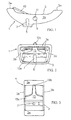
- buckle 1 according to the invention comprises a frame 3 having a substantially rectangular profile, formed by four sides parallel two by two, two of which are shorter sides 3a and two of which are longer sides 3b. Said greater sides 3b have a curved profile (as clearly visible in Figures 1 and 2), which gives the typical "bateau" shape to frame 3.
- Said frame 1 comprises a crosspiece 5 that joins the two longer sides 3b and on which is obtained, preferably in middle position with respect to said sides 3b, a fixed pin 7, suitable for entering into the buckle hole.
- Said pin 7 can be straight, as represented in the Figures, or, preferably, hook-like bent, so to hold the aforesaid belt more effectively.
- buckle 1 further comprises a transverse stem 9 placed between the longer sides 3b, whose ends are received in appropriate holes 11 obtained in said sides, and a tongue 13 pivotally mounted onto said stem 9.
- Said tongue 13 length is substantially equal to the distance between said holes 11 and one of the shorter sides 3a of frame 3, so that its tip 13b - suitable for entering into the buckle hole - can rest onto said shorter side 3a, so to cooperate with said side in order to hold said belt.
- said shorter side 3a onto which the tongue 13 tip rests is preferably the shorter side closer to the fixed pin 7, and toward which said pin 7 is in case hook-like bent.
- stem 9, onto which tongue 13 is mounted in lifted and staggered position with respect to crosspiece 5 can be fastened to frame 3 so that pin 7 is positioned below tongue 13 and comprised between stem 9 and the shorter side 3a onto which said tongue tip 13b rests.
- pin 7 does not interfere with the pivoting movement of said tongue; on the contrary, as it will be better disclosed afterwards, said pin 7 and said tongue 13, thanks to the staggered position, can effectively cooperate to better hold the belts.
- said tongue has a triangular or funnel-like shape so that said tongue width at base 13a can be made substantially equal to the internal distance between the longer sides 3b of frame 3; this way, tip 13b of tongue 13 will turn out to be always centered with respect to frame 3, not needing locks to hold the tongue in the right position.
- tongue 13 is mounted onto frame 3, the base 13a around said transverse stem 9 thus passing through tongue 13 transversely.
- the transverse stem 9 can also be eliminated, directly introducing into holes 11 the ends of said base 13a said tongue 13, in case providing them with appropriate projections.
- buckle 1 is preferably made of metal, but any material being sufficiently stiff to give the buckle the required mechanical resistance can be used, in particular plastic materials such as polypropylene or nylon.
- buckle 1 is preferably made by melting and following casting in proper moulds.
- frame 3 and stem 9 can be manufactured as separated pieces (in this case, taking care of defining the facing holes 11 I in walls 3b of frame 3 for introducing stem 9), but also said frame and said stem can be manufactured as a single body employing a single mould.
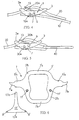
- buckle 1 With reference to Figure 4, an application of buckle 1 according to the invention is shown in order to hold and to connect two belts 10,20 formed by strips of flexible material (for instance, leather or plastic) provided with a plurality of aligned holes.
- flexible material for instance, leather or plastic
- the first belt 10 is fastened to buckle 1 thanks to the fixed pin 7, which enters into a hole 10a of said first belt 10, holding it.
- the second belt 20 passes through frame 3 of buckle 1 and it is fastened to said buckle thanks to tongue 13, which enters through a hole 20a of said second belt and hold it pressed against side 3a of frame 3, holding it.
- said tongue base presses on the first belt 10, helping to firmly hold it.
- the fixed pin 7 enters into a first hole 30a of belt 30, obtained near said belt end, holding it.
- the belt 30 is then bent onto itself and passes again inside frame 3 of buckle 1, so that the tongue 13 tip can enter through a second hole 30b of said belt 30, holding it in the wanted configuration.
- Said represented configuration can turn out to be useful, for instance, in the sadlery field, in order to connect a metal ring 40 to belt 30, as represented in Figure 5.
- the staggered position of stem 9 onto which tongue 13 is mounted with respect to pin 7 causes said tongue base to press on belt 30 near pin 7, helping to firmly hold it.
- frame 3' and tongue 13' of buckle 1' are initially manufactured as flat elements (Figure 6), for instance obtained by pressing a tinplate sheet.
- the frame 3' has a substantially rectangular profile and comprises two shorter sides 3'a and two longer sides 3'b.
- tongue 13' has a funnel-like shape, with a tip 13'b and a widened base 13'a.
- said longer sides 3'b are further provided two arms 5'a, one on each side, having a length substantially equal to half the distance between said longer sides 3'b, each ending with a tooth 7'a.
- buckle 1' In order to manufacture buckle 1' (Figure 7), teeth 7'a are bent of 90° with respect to arms 5'a, said arms 5'a are in their turn bent of 90° with respect to the longer sides 3'b of frame 3' and finally said sides 3'b are bent of 90° with respect to the shorter sides 3'a.
- the "bateau" shape is given to frame 3' and the two arms 5'a, which are bent toward the inside of said frame 3', form a crosspiece 5'; moreover, the two teeth 7'a, which are placed side by side each other, form a pin 7', onto which a belt hole can be inserted.
- tongue 13' is mounted by making projections 9' at the base 13'a of said tongue to enter into holes 11' that are provided on the longer sides 3'b of frame 3'.
Landscapes
- Buckles (AREA)
- Yarns And Mechanical Finishing Of Yarns Or Ropes (AREA)
- Supports For Plants (AREA)
- Slide Fasteners, Snap Fasteners, And Hook Fasteners (AREA)
- Automotive Seat Belt Assembly (AREA)
Claims (13)
- Boucle (1 ; 1') comprenant :- un cadre (3 ; 3') de profil essentiellement rectangulaire, formé par quatre côtés (3a, 3b ; 3'a, 3'b) parallèles deux à deux, un élément transversal (5 ; 5') placé entre lesdits deux côtés opposés (3b ; 3'b) dudit cadre ;- un ergot fixe (7 ; 7') placé sur ledit élément transversal (5 ; 5'), de préférence en position médiane entre lesdits deux côtés opposés ;- une languette (13 ; 13') montée dans le sens transversal et de manière à pouvoir pivoter par rapport auxdits deux côtés opposés (3b ; 3'b) ;caractérisée en ce que lesdits deux côtés opposés (3b ; 3'b) présentent un profil incurvé et en ce que ladite languette (13 ; 13') est montée entre lesdits deux côtés opposés incurvés (3b ; 3'b) en position surélevée et décalée par rapport audit élément transversal (5 ; 5') portant ledit ergot fixe (7 ; 7').
- Boucle (1 ; 1') selon la revendication 1, dans laquelle ladite languette a une forme triangulaire ou en entonnoir et s'élargit de la pointe (13b ; 13'b) vers la base (13a ; 13'a).
- Boucle (1 ; 1') selon la revendication 2, dans laquelle la largeur de la base de ladite languette (13 ; 13') est essentiellement égale à la distance intérieure qui sépare lesdits deux côtés opposés (3b ; 3'b).
- Boucle (1) selon l'une quelconque des revendications précédentes, dans laquelle ladite boucle comprend une tige (9) montée dans le sens transversal entre lesdits deux côtés opposés (3b) et dans laquelle la base (13a) de ladite languette (13) est repliée et repiquée autour de ladite tige.
- Boucle (1) selon la revendication 4, dans laquelle lesdits côtés opposés (3b) comportent une paire de trous opposés (11) pour recevoir les extrémités de ladite tige (9).
- Boucle (1) selon la revendication 3, dans laquelle lesdits deux côtés opposés comprennent une paire de trous opposés (11') pour recevoir des protubérances correspondantes (9') formées au niveau des extrémités de la base (13'a) de ladite languette (13').
- Boucle (1 ; 1') selon la revendication 5 ou 6, dans laquelle la longueur de ladite languette (13 ; 13') de la base (13a ; 13'a) à la pointe (13b ; 13'b) est essentiellement égale à la distance qui sépare lesdits trous (11 ; 11') et l'un des côtés (3a ; 3'a) du cadre (3 ; 3') perpendiculaire auxdits deux côtés opposés, de sorte que ladite pointe de ladite languette peut reposer sur ledit côté perpendiculaire.
- Boucle (1 ; 1') selon la revendication 7, dans laquelle ledit côté perpendiculaire (3a ; 3'a) sur lequel repose ladite pointe de ladite languette est le côté le plus proche dudit élément transversal (5 ; 5').
- Boucle (1') selon la revendication 1, dans laquelle ledit élément transversal (5') est formé par deux bras (5'a), qui sont chacun fixés à l'un desdits deux côtés opposés (3'b), ont chacun une longueur essentiellement égale à la moitié de la distance qui sépare lesdits deux côtés et se terminent chacun par une dent courbée (7'a), lesdites dents (7'a) desdits bras (5'a) apparaissant ainsi en vis-à-vis et formant ainsi ledit ergot (7').
- Boucle (1 ; 1) selon l'une quelconque des revendications précédentes, dans laquelle ledit ergot (7, 7') est replié en forme de crochet.
- Boucle (1 ; 1') selon l'une quelconque des revendications précédentes, dans laquelle ladite boucle est faite de métal.
- Boucle (1 ; 1') selon l'une quelconque des revendications 1 à 10 précédentes, dans laquelle ladite boucle est faite de matière plastique, en particulier de polypropylène ou de nylon.
- Procédé de fabrication d'une boucle (1'), comprenant l'étape consistant à :- fournir une feuille de fer blanc ;caractérisé en ce qu'il comprend en outre les étapes consistant à :- découper, dans ladite feuille, par exemple par pressage, un cadre (3') de profil essentiellement rectangulaire, formé par quatre côtés (3'a, 3'b) parallèles deux à deux, deux côtés opposés (3'b) dudit cadre présentant un profil incurvé et comportant chacun un bras (5'a) ayant une longueur essentiellement égale à la moitié de la distance qui sépare lesdits deux côtés opposés et se terminant par une dent (7'a) ;- former une paire de trous opposés (11') dans lesdits côtés opposés (3'b) en position surélevée et décalée par rapport auxdits bras (5'a) ;- former, dans ladite feuille, une languette (13'), ayant une forme triangulaire ou en entonnoir, qui s'élargit de la pointe (13'b) vers la base (13'a), ladite base (13'a) ayant une largeur essentiellement égale à la distance qui sépare lesdits deux côtés opposés (3'b) dudit cadre (3') et comportant une protubérance (9') à chaque extrémité ;- plier lesdites dents (7'a) à environ 90° par rapport auxdits bras (5'a) ;- plier ledit bras (5'a) à environ 90° par rapport auxdits côtés opposés (3'b) ;- plier lesdits deux côtés opposés (3'b) à environ 90° par rapport aux deux autres côtés (3'a) dudit cadre (3'), de sorte que lesdits bras (5'a) soient tournés vers l'intérieur dudit cadre (3') ; et- monter ladite languette (13') sur ledit cadre (3') en faisant entrer lesdites protubérances (9') dans lesdits trous (11').
Priority Applications (4)
| Application Number | Priority Date | Filing Date | Title |
|---|---|---|---|
| ES05425283T ES2296120T3 (es) | 2005-05-03 | 2005-05-03 | Hebilla y procedimiento de fabricacion de dicha hebilla. |
| DE602005002934T DE602005002934T2 (de) | 2005-05-03 | 2005-05-03 | Schnalle und Verfahren zur Herstellung der Schnalle |
| AT05425283T ATE375735T1 (de) | 2005-05-03 | 2005-05-03 | Schnalle und verfahren zur herstellung der schnalle |
| EP05425283A EP1719428B1 (fr) | 2005-05-03 | 2005-05-03 | Boucle et procédé pour fabriquer cette boucle |
Applications Claiming Priority (1)
| Application Number | Priority Date | Filing Date | Title |
|---|---|---|---|
| EP05425283A EP1719428B1 (fr) | 2005-05-03 | 2005-05-03 | Boucle et procédé pour fabriquer cette boucle |
Publications (2)
| Publication Number | Publication Date |
|---|---|
| EP1719428A1 EP1719428A1 (fr) | 2006-11-08 |
| EP1719428B1 true EP1719428B1 (fr) | 2007-10-17 |
Family
ID=35197693
Family Applications (1)
| Application Number | Title | Priority Date | Filing Date |
|---|---|---|---|
| EP05425283A Expired - Lifetime EP1719428B1 (fr) | 2005-05-03 | 2005-05-03 | Boucle et procédé pour fabriquer cette boucle |
Country Status (4)
| Country | Link |
|---|---|
| EP (1) | EP1719428B1 (fr) |
| AT (1) | ATE375735T1 (fr) |
| DE (1) | DE602005002934T2 (fr) |
| ES (1) | ES2296120T3 (fr) |
Family Cites Families (8)
| Publication number | Priority date | Publication date | Assignee | Title |
|---|---|---|---|---|
| DE1791C (de) * | 1878-01-16 | O. LEVERKUS in Manchester | Doppelschnalle zur Verbindung von zwei freien Enden | |
| FR547709A (fr) * | 1922-01-25 | 1922-12-22 | Boucle de harnachement | |
| US1479515A (en) * | 1922-11-06 | 1924-01-01 | Russell Theodore | Tongue buckle |
| GB646523A (en) * | 1948-03-08 | 1950-11-22 | Epiard Freres | A device for attaching a buckle to a strap and a buckle particularly adapted for such a device |
| US2531226A (en) * | 1949-04-01 | 1950-11-21 | Licursi Matthew | Buckle |
| FR1186576A (fr) * | 1957-11-19 | 1959-08-27 | Boucle avec languette attenante | |
| US3175266A (en) * | 1963-04-23 | 1965-03-30 | Louis J Mcmullen | Fastener |
| FR2646063B1 (fr) * | 1989-04-21 | 1991-08-16 | Henon Gerard | Boucle de decoration pour article de maroquinerie |
-
2005
- 2005-05-03 EP EP05425283A patent/EP1719428B1/fr not_active Expired - Lifetime
- 2005-05-03 AT AT05425283T patent/ATE375735T1/de not_active IP Right Cessation
- 2005-05-03 DE DE602005002934T patent/DE602005002934T2/de not_active Expired - Fee Related
- 2005-05-03 ES ES05425283T patent/ES2296120T3/es not_active Expired - Lifetime
Also Published As
| Publication number | Publication date |
|---|---|
| DE602005002934T2 (de) | 2008-08-07 |
| EP1719428A1 (fr) | 2006-11-08 |
| ES2296120T3 (es) | 2008-04-16 |
| DE602005002934D1 (de) | 2007-11-29 |
| ATE375735T1 (de) | 2007-11-15 |
Similar Documents
| Publication | Publication Date | Title |
|---|---|---|
| US7617801B2 (en) | Buckle for pet collar | |
| EP0804886A2 (fr) | Curseur à verrouillage automatique et appareillage de moulage du couvercle du curseur | |
| CA2184659C (fr) | Substitut de bouton utilise comme moyen d'assemblage | |
| US20130269629A1 (en) | Magnetic buckle for a pet collar or the like | |
| US5189763A (en) | Strap clasp | |
| JP2001286307A (ja) | 紐止め具 | |
| US8429798B1 (en) | Fastening device | |
| CN102573555B (zh) | 带扣 | |
| EP1719428B1 (fr) | Boucle et procédé pour fabriquer cette boucle | |
| US7797800B2 (en) | Buckle for connecting a wrist strap to the handgrip of a pole for use in sporting activities | |
| JP2000184905A (ja) | 開閉用押圧止具 | |
| EP0303893A1 (fr) | Boucle en matière plastique | |
| HK1046222B (zh) | 一种主要用於手表表带的连接两条柔性带的卡紧扣 | |
| US20150042091A1 (en) | Brunnian link making device and method | |
| EP2047744B1 (fr) | Boucle pour collier d'animal domestique | |
| KR20100097202A (ko) | 후크 앤 아이 파스너 | |
| US795308A (en) | Fastener for attaching loops and buckles to belts, straps, collars, &c. | |
| US2405271A (en) | Fastening means | |
| IT201800004167A1 (it) | Dispositivo di chiusura a sgancio rapido per monili | |
| JP3064313U (ja) | ホック係合体 | |
| KR200387187Y1 (ko) | 혁대 | |
| US734951A (en) | Metal fastener. | |
| US266652A (en) | Island | |
| KR20070101973A (ko) | 결속구 | |
| JP3442712B2 (ja) | 開閉用押圧止具 |
Legal Events
| Date | Code | Title | Description |
|---|---|---|---|
| PUAI | Public reference made under article 153(3) epc to a published international application that has entered the european phase |
Free format text: ORIGINAL CODE: 0009012 |
|
| AK | Designated contracting states |
Kind code of ref document: A1 Designated state(s): AT BE BG CH CY CZ DE DK EE ES FI FR GB GR HU IE IS IT LI LT LU MC NL PL PT RO SE SI SK TR |
|
| AX | Request for extension of the european patent |
Extension state: AL BA HR LV MK YU |
|
| 17P | Request for examination filed |
Effective date: 20061103 |
|
| GRAP | Despatch of communication of intention to grant a patent |
Free format text: ORIGINAL CODE: EPIDOSNIGR1 |
|
| AKX | Designation fees paid |
Designated state(s): AT BE BG CH CY CZ DE DK EE ES FI FR GB GR HU IE IS IT LI LT LU MC NL PL PT RO SE SI SK TR |
|
| GRAS | Grant fee paid |
Free format text: ORIGINAL CODE: EPIDOSNIGR3 |
|
| GRAA | (expected) grant |
Free format text: ORIGINAL CODE: 0009210 |
|
| AK | Designated contracting states |
Kind code of ref document: B1 Designated state(s): AT BE BG CH CY CZ DE DK EE ES FI FR GB GR HU IE IS IT LI LT LU MC NL PL PT RO SE SI SK TR |
|
| REG | Reference to a national code |
Ref country code: GB Ref legal event code: FG4D |
|
| REG | Reference to a national code |
Ref country code: CH Ref legal event code: EP |
|
| REG | Reference to a national code |
Ref country code: IE Ref legal event code: FG4D |
|
| REF | Corresponds to: |
Ref document number: 602005002934 Country of ref document: DE Date of ref document: 20071129 Kind code of ref document: P |
|
| REG | Reference to a national code |
Ref country code: CH Ref legal event code: NV Representative=s name: KEMIA SA |
|
| NLV1 | Nl: lapsed or annulled due to failure to fulfill the requirements of art. 29p and 29m of the patents act | ||
| REG | Reference to a national code |
Ref country code: ES Ref legal event code: FG2A Ref document number: 2296120 Country of ref document: ES Kind code of ref document: T3 |
|
| PG25 | Lapsed in a contracting state [announced via postgrant information from national office to epo] |
Ref country code: NL Free format text: LAPSE BECAUSE OF FAILURE TO SUBMIT A TRANSLATION OF THE DESCRIPTION OR TO PAY THE FEE WITHIN THE PRESCRIBED TIME-LIMIT Effective date: 20071017 Ref country code: SE Free format text: LAPSE BECAUSE OF FAILURE TO SUBMIT A TRANSLATION OF THE DESCRIPTION OR TO PAY THE FEE WITHIN THE PRESCRIBED TIME-LIMIT Effective date: 20080117 |
|
| PG25 | Lapsed in a contracting state [announced via postgrant information from national office to epo] |
Ref country code: BG Free format text: LAPSE BECAUSE OF FAILURE TO SUBMIT A TRANSLATION OF THE DESCRIPTION OR TO PAY THE FEE WITHIN THE PRESCRIBED TIME-LIMIT Effective date: 20080117 Ref country code: IS Free format text: LAPSE BECAUSE OF FAILURE TO SUBMIT A TRANSLATION OF THE DESCRIPTION OR TO PAY THE FEE WITHIN THE PRESCRIBED TIME-LIMIT Effective date: 20080217 Ref country code: LT Free format text: LAPSE BECAUSE OF FAILURE TO SUBMIT A TRANSLATION OF THE DESCRIPTION OR TO PAY THE FEE WITHIN THE PRESCRIBED TIME-LIMIT Effective date: 20071017 Ref country code: SI Free format text: LAPSE BECAUSE OF FAILURE TO SUBMIT A TRANSLATION OF THE DESCRIPTION OR TO PAY THE FEE WITHIN THE PRESCRIBED TIME-LIMIT Effective date: 20071017 Ref country code: PT Free format text: LAPSE BECAUSE OF FAILURE TO SUBMIT A TRANSLATION OF THE DESCRIPTION OR TO PAY THE FEE WITHIN THE PRESCRIBED TIME-LIMIT Effective date: 20080317 Ref country code: PL Free format text: LAPSE BECAUSE OF FAILURE TO SUBMIT A TRANSLATION OF THE DESCRIPTION OR TO PAY THE FEE WITHIN THE PRESCRIBED TIME-LIMIT Effective date: 20071017 |
|
| PG25 | Lapsed in a contracting state [announced via postgrant information from national office to epo] |
Ref country code: AT Free format text: LAPSE BECAUSE OF FAILURE TO SUBMIT A TRANSLATION OF THE DESCRIPTION OR TO PAY THE FEE WITHIN THE PRESCRIBED TIME-LIMIT Effective date: 20071017 |
|
| ET | Fr: translation filed | ||
| PG25 | Lapsed in a contracting state [announced via postgrant information from national office to epo] |
Ref country code: CZ Free format text: LAPSE BECAUSE OF FAILURE TO SUBMIT A TRANSLATION OF THE DESCRIPTION OR TO PAY THE FEE WITHIN THE PRESCRIBED TIME-LIMIT Effective date: 20071017 Ref country code: DK Free format text: LAPSE BECAUSE OF FAILURE TO SUBMIT A TRANSLATION OF THE DESCRIPTION OR TO PAY THE FEE WITHIN THE PRESCRIBED TIME-LIMIT Effective date: 20071017 |
|
| PGFP | Annual fee paid to national office [announced via postgrant information from national office to epo] |
Ref country code: ES Payment date: 20080527 Year of fee payment: 4 |
|
| PLBE | No opposition filed within time limit |
Free format text: ORIGINAL CODE: 0009261 |
|
| STAA | Information on the status of an ep patent application or granted ep patent |
Free format text: STATUS: NO OPPOSITION FILED WITHIN TIME LIMIT |
|
| PG25 | Lapsed in a contracting state [announced via postgrant information from national office to epo] |
Ref country code: SK Free format text: LAPSE BECAUSE OF FAILURE TO SUBMIT A TRANSLATION OF THE DESCRIPTION OR TO PAY THE FEE WITHIN THE PRESCRIBED TIME-LIMIT Effective date: 20071017 Ref country code: BE Free format text: LAPSE BECAUSE OF FAILURE TO SUBMIT A TRANSLATION OF THE DESCRIPTION OR TO PAY THE FEE WITHIN THE PRESCRIBED TIME-LIMIT Effective date: 20071017 Ref country code: RO Free format text: LAPSE BECAUSE OF FAILURE TO SUBMIT A TRANSLATION OF THE DESCRIPTION OR TO PAY THE FEE WITHIN THE PRESCRIBED TIME-LIMIT Effective date: 20071017 |
|
| 26N | No opposition filed |
Effective date: 20080718 |
|
| PGFP | Annual fee paid to national office [announced via postgrant information from national office to epo] |
Ref country code: DE Payment date: 20080725 Year of fee payment: 4 Ref country code: IE Payment date: 20080529 Year of fee payment: 4 |
|
| PG25 | Lapsed in a contracting state [announced via postgrant information from national office to epo] |
Ref country code: MC Free format text: LAPSE BECAUSE OF NON-PAYMENT OF DUE FEES Effective date: 20080531 |
|
| PG25 | Lapsed in a contracting state [announced via postgrant information from national office to epo] |
Ref country code: EE Free format text: LAPSE BECAUSE OF FAILURE TO SUBMIT A TRANSLATION OF THE DESCRIPTION OR TO PAY THE FEE WITHIN THE PRESCRIBED TIME-LIMIT Effective date: 20071017 Ref country code: GR Free format text: LAPSE BECAUSE OF FAILURE TO SUBMIT A TRANSLATION OF THE DESCRIPTION OR TO PAY THE FEE WITHIN THE PRESCRIBED TIME-LIMIT Effective date: 20080118 |
|
| PG25 | Lapsed in a contracting state [announced via postgrant information from national office to epo] |
Ref country code: FI Free format text: LAPSE BECAUSE OF FAILURE TO SUBMIT A TRANSLATION OF THE DESCRIPTION OR TO PAY THE FEE WITHIN THE PRESCRIBED TIME-LIMIT Effective date: 20071017 |
|
| PG25 | Lapsed in a contracting state [announced via postgrant information from national office to epo] |
Ref country code: CY Free format text: LAPSE BECAUSE OF FAILURE TO SUBMIT A TRANSLATION OF THE DESCRIPTION OR TO PAY THE FEE WITHIN THE PRESCRIBED TIME-LIMIT Effective date: 20071017 |
|
| REG | Reference to a national code |
Ref country code: CH Ref legal event code: PL |
|
| GBPC | Gb: european patent ceased through non-payment of renewal fee |
Effective date: 20090503 |
|
| PG25 | Lapsed in a contracting state [announced via postgrant information from national office to epo] |
Ref country code: LI Free format text: LAPSE BECAUSE OF NON-PAYMENT OF DUE FEES Effective date: 20090531 Ref country code: CH Free format text: LAPSE BECAUSE OF NON-PAYMENT OF DUE FEES Effective date: 20090531 |
|
| REG | Reference to a national code |
Ref country code: FR Ref legal event code: ST Effective date: 20100129 |
|
| PG25 | Lapsed in a contracting state [announced via postgrant information from national office to epo] |
Ref country code: IE Free format text: LAPSE BECAUSE OF NON-PAYMENT OF DUE FEES Effective date: 20090504 Ref country code: FR Free format text: LAPSE BECAUSE OF NON-PAYMENT OF DUE FEES Effective date: 20090602 |
|
| PGFP | Annual fee paid to national office [announced via postgrant information from national office to epo] |
Ref country code: FR Payment date: 20080516 Year of fee payment: 4 |
|
| PG25 | Lapsed in a contracting state [announced via postgrant information from national office to epo] |
Ref country code: GB Free format text: LAPSE BECAUSE OF NON-PAYMENT OF DUE FEES Effective date: 20090503 |
|
| PG25 | Lapsed in a contracting state [announced via postgrant information from national office to epo] |
Ref country code: DE Free format text: LAPSE BECAUSE OF NON-PAYMENT OF DUE FEES Effective date: 20091201 |
|
| REG | Reference to a national code |
Ref country code: ES Ref legal event code: FD2A Effective date: 20090504 |
|
| PG25 | Lapsed in a contracting state [announced via postgrant information from national office to epo] |
Ref country code: LU Free format text: LAPSE BECAUSE OF NON-PAYMENT OF DUE FEES Effective date: 20080503 Ref country code: HU Free format text: LAPSE BECAUSE OF FAILURE TO SUBMIT A TRANSLATION OF THE DESCRIPTION OR TO PAY THE FEE WITHIN THE PRESCRIBED TIME-LIMIT Effective date: 20080418 |
|
| PG25 | Lapsed in a contracting state [announced via postgrant information from national office to epo] |
Ref country code: TR Free format text: LAPSE BECAUSE OF FAILURE TO SUBMIT A TRANSLATION OF THE DESCRIPTION OR TO PAY THE FEE WITHIN THE PRESCRIBED TIME-LIMIT Effective date: 20071017 |
|
| PG25 | Lapsed in a contracting state [announced via postgrant information from national office to epo] |
Ref country code: ES Free format text: LAPSE BECAUSE OF NON-PAYMENT OF DUE FEES Effective date: 20090504 |
|
| PGFP | Annual fee paid to national office [announced via postgrant information from national office to epo] |
Ref country code: IT Payment date: 20080531 Year of fee payment: 4 |