EP1719434A2 - System zur Bewegung von Elementen eines Möbelstücks - Google Patents
System zur Bewegung von Elementen eines Möbelstücks Download PDFInfo
- Publication number
- EP1719434A2 EP1719434A2 EP06009022A EP06009022A EP1719434A2 EP 1719434 A2 EP1719434 A2 EP 1719434A2 EP 06009022 A EP06009022 A EP 06009022A EP 06009022 A EP06009022 A EP 06009022A EP 1719434 A2 EP1719434 A2 EP 1719434A2
- Authority
- EP
- European Patent Office
- Prior art keywords
- fitment
- space
- base body
- guiding
- vertical
- Prior art date
- Legal status (The legal status is an assumption and is not a legal conclusion. Google has not performed a legal analysis and makes no representation as to the accuracy of the status listed.)
- Withdrawn
Links
- 238000004873 anchoring Methods 0.000 claims abstract 3
- 238000011144 upstream manufacturing Methods 0.000 claims description 6
- 238000005096 rolling process Methods 0.000 claims description 3
- 230000008878 coupling Effects 0.000 claims 1
- 238000010168 coupling process Methods 0.000 claims 1
- 238000005859 coupling reaction Methods 0.000 claims 1
- 230000004913 activation Effects 0.000 description 1
- 230000002265 prevention Effects 0.000 description 1
- 238000006467 substitution reaction Methods 0.000 description 1
Images

Classifications
-
- A—HUMAN NECESSITIES
- A47—FURNITURE; DOMESTIC ARTICLES OR APPLIANCES; COFFEE MILLS; SPICE MILLS; SUCTION CLEANERS IN GENERAL
- A47B—TABLES; DESKS; OFFICE FURNITURE; CABINETS; DRAWERS; GENERAL DETAILS OF FURNITURE
- A47B96/00—Details of cabinets, racks or shelf units not covered by a single one of groups A47B43/00 - A47B95/00; General details of furniture
- A47B96/16—Drawers or movable shelves coupled to doors
-
- A—HUMAN NECESSITIES
- A47—FURNITURE; DOMESTIC ARTICLES OR APPLIANCES; COFFEE MILLS; SPICE MILLS; SUCTION CLEANERS IN GENERAL
- A47B—TABLES; DESKS; OFFICE FURNITURE; CABINETS; DRAWERS; GENERAL DETAILS OF FURNITURE
- A47B81/00—Cabinets or racks specially adapted for other particular purposes, e.g. for storing guns or skis
- A47B81/002—Corner cabinets; Cabinets designed for being placed in a corner or a niche
-
- A—HUMAN NECESSITIES
- A47—FURNITURE; DOMESTIC ARTICLES OR APPLIANCES; COFFEE MILLS; SPICE MILLS; SUCTION CLEANERS IN GENERAL
- A47B—TABLES; DESKS; OFFICE FURNITURE; CABINETS; DRAWERS; GENERAL DETAILS OF FURNITURE
- A47B2210/00—General construction of drawers, guides and guide devices
- A47B2210/05—Metal wire baskets for vertical drawers
-
- A—HUMAN NECESSITIES
- A47—FURNITURE; DOMESTIC ARTICLES OR APPLIANCES; COFFEE MILLS; SPICE MILLS; SUCTION CLEANERS IN GENERAL
- A47B—TABLES; DESKS; OFFICE FURNITURE; CABINETS; DRAWERS; GENERAL DETAILS OF FURNITURE
- A47B88/00—Drawers for tables, cabinets or like furniture; Guides for drawers
- A47B88/40—Sliding drawers; Slides or guides therefor
- A47B88/42—Vertically-oriented drawers, i.e. drawers where the height exceeds the width
Definitions
- the present invention relates to the technical field concerning the moving fitments in a piece of furniture, e.g. an angle-shaped element.
- the document EP 0 441 919 describes a piece of furniture, aimed at being installed in a corner of a room and having two horizontally sliding, built-in fitments, inner and outer, situated one beside the other in a basic unit.
- the outer and inner fitments are connected by levers, which allow the inner built-in fitment to be moved toward or away from the free space, while the outer fitment, mounted on a rotating guide, is removed from the basic unit in a position corresponding to its front face and rotated by at least 90° with respect to a vertical axis.
- the outer and inner fitment include: a flat sliding frame, arranged vertically; a plurality of baskets, suspended on one side on respective flat sliding frames, extending horizontally from the frames.
- the sliding frame of the inner fitment is removably mounted on a flat, stationary guide frame.
- the piece of furniture described in the above document has disadvantages deriving from the assembling of its parts.
- the object of the present invention is to propose a system for moving fitments in an angle-shaped piece of furniture, which allows its easy and rapid assembling.
- Another object of the present invention is to propose a system obtained by elements, which can be assembled also by not particularly skilled operators.
- a further object of the present invention is to propose a system of a simple concept and obtained at low cost.
- the enclosed Figures show a system for moving fitments in a piece of furniture, e.g. angle shaped.
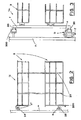
- the system includes: a base body 1, whose inner, rear, vertical wall P carries, longitudinally fastened thereto, known guiding means, e.g. a lower track 23 and an upper track 24, to whose inner, transverse, vertical wall Pt, the lower part of a guiding arm B is articulated, rotating with respect to a vertical axis Z.
- known guiding means e.g. a lower track 23 and an upper track 24, to whose inner, transverse, vertical wall Pt, the lower part of a guiding arm B is articulated, rotating with respect to a vertical axis Z.
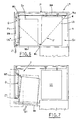
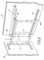
- a stationary guide 300 is fastened to the upper part of the wall Pt, as shown in Figure 3.
- the base body 1 has a first space S1, delimited thereinside, near its opening A, and a second inner space S2, adjacent to the first space S1.
- the outer fitment Ue ( Figure 3) includes a vertical frame T, on which baskets 3, e.g. two, are suspended.
- the vertical frame T has guiding elements 30 of known type, whose lower part couple telescopically with the rotating guiding arm B and whose upper part couples with the stationary guide 300.
- the inner fitment Ui ( Figure 2) includes containers 2, e.g. two, mutually connected by vertical uprights 22 and carrying known guiding and/or rolling means R, R*.
- the first guiding means R are defined by a roll having a horizontal axis and the second guiding means R* include rolls having vertical axis, guided respectively in the lower track 23 and the upper track 24.
- the inner fitment Ui carries, fastened thereto, connecting elements 200, e.g. as shown in Figure 2, brackets fixed to the lower container 2.
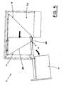
- the outer fitment Ue and the inner fitment Ui are connected by connecting means F, including a cable 4, which is set loop-like on three idle elements 5a, 5b, 5c (e.g. pulleys), fastened e.g. to the bottom of the base body 1.
- connecting means F including a cable 4, which is set loop-like on three idle elements 5a, 5b, 5c (e.g. pulleys), fastened e.g. to the bottom of the base body 1.
- the cable 4 is fastened to the connecting elements 200 of the inner fitment Ui and fixed in a point K to the rotating guiding arm B, to define an upstream branch 40 and a downstream branch 49.
- the connecting means F include also tension means 6 of known type, e.g. coaxial springs or outer tension devices, fastened to the base body 1, so as to act on the cable 4 in order to keep it taut.
- tension means 6 of known type, e.g. coaxial springs or outer tension devices, fastened to the base body 1, so as to act on the cable 4 in order to keep it taut.
- the outer fitment Ue and the inner fitment Ui take:
- the guiding elements 30, sliding in the stationary guide 300 are removed from the latter and the guiding arm B rotates on the vertical axis Z, which consequently draws the upstream branch 40 of the cable 4 to make the inner fitment Ui move longitudinally, so as to free the second space S2 and occupy the first space S1, thus making the containers 2 accessible.
- the user After having used the containers 2, the user must restore the first closing position I, therefore he/she must make the guiding arm B rotate in the direction opposite to the arrow W, bring the outer fitment Ue back to the intermediate position M and then push it inwards, in the direction opposite to the arrow J.
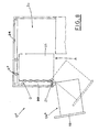
- the upper part of the inner, transverse, vertical wall Pt of the base body 1 ( Figure 9), carries fastened thereto, a stationary guide 39, in which a shaped path G is made, and the lower part of the same wall Pt carries, articulated thereto, a guiding arm B1, rotating on a vertical axis Z1.
- the axis Z1 is contained in a vertical upright V, which is integral with the guiding arm B1 and which extends upwards up to the stationary guide 39.
- the outer fitment Ue* obtained according to the second embodiment ( Figure 9), includes a vertical frame T1, whose outer upright carries, fastened thereto, a door 10 of the piece of furniture.
- the baskets are suspended on the frame T1, which has first and second guiding elements 38, 37 of known type: the first guiding elements 38 couple telescopically with the rotating guiding arm B1 and the second guiding elements 37 couple with the stationary guide 39, so as to enter the shaped guiding path G.
- the inner fitment Ui like the one described in the first embodiment, and the outer fitment Ue* are connected by the same connecting means F ( Figure 6), as described previously, with reference to the first embodiment.
- the outer fitment Ue* and the inner fitment Ui take: a first closing position I* ( Figure 6), in which the outer fitment Ue* is situated in the first space S1 and the inner fitment Ui in the second space S2; a second position O* ( Figure 8), in which the outer fitment Ue* is rotated outwards on the vertical axis Z1, to free the first space S1 and the inner fitment Ui is moved longitudinally to occupy the first space S1 and to free the second space S2.
- the guiding arm B1 rotates, in step relation with the sliding of the first and second guiding elements 38, 37, with respect to the vertical axis Z1 ( Figures 7, 9), which causes the rotation of the outer fitment Ue* in the direction of the arrow W1 ( Figure 7), until the outer fitment Ue* is removed laterally from the first space S1.
- the rotation of the guiding arm B1 causes the subsequent activation, as already described with reference to the first embodiment, of the connecting means F, which make the inner fitment Ui move longitudinally, to free the second space S2 and occupy the first space S1.
- the user After having used the baskets 3 and/or the containers 2, the user must resume the first closing position I*, therefore he/she must make the guiding arm B1 rotate in the direction opposite to the arrow W1 and push the outer fitment Ue* inwards, in the direction opposite to the arrow J1.
- the system for moving fitments in a piece of furniture proposed by the present invention includes advantageously the connecting means F, including a cable 4, which is mounted loop-like on the pulleys 5a, 5b, 5c and which can be easily positioned on the bottom, or on the top of the base body 1 by any operator, which results in a considerable reduction of assembling time and costs.
- the tension means 6, associated to the connecting means F, allow the cable 4 to maintain the initial tautness in all the intermediate positions of the passage of the outer fitments Ue, Ue* and the inner fitment Ui from the first position I, I*, to the second position O, O*, and vice versa.
- the combination of the guiding means 23, 24, the guiding arm B, B1, the stationary guide 300, 39 and the connecting means F, increases the operation safety of the system for moving the outer and inner fitments Ue, Ue*, Ui, that is prevention of the movement jamming and locking in the positions assumed by the outer and inner fitments Ue, Ue*, Ui.
- the simplicity of the connecting means F facilitates the rapid and cheap substitution of the cable and/or the pulleys.
- the above described system for moving fitments is particularly advantageous because of its adaptability to pieces of furniture of different dimensions, since the pulleys 5a, 5b, 5c, the tension means 6 are suitably placed, and the used guiding means 23, 23 and the cable 4 have suitable dimensions, in relation to the length of the base body 1.
Landscapes
- Drawers Of Furniture (AREA)
- Hinges (AREA)
Applications Claiming Priority (1)
| Application Number | Priority Date | Filing Date | Title |
|---|---|---|---|
| IT000305A ITBO20050305A1 (it) | 2005-05-03 | 2005-05-03 | Sistema per la movimentazione di unita' in un elemento di mobile |
Publications (2)
| Publication Number | Publication Date |
|---|---|
| EP1719434A2 true EP1719434A2 (de) | 2006-11-08 |
| EP1719434A3 EP1719434A3 (de) | 2007-01-17 |
Family
ID=36888975
Family Applications (1)
| Application Number | Title | Priority Date | Filing Date |
|---|---|---|---|
| EP06009022A Withdrawn EP1719434A3 (de) | 2005-05-03 | 2006-05-02 | System zur Bewegung von Elementen eines Möbelstücks |
Country Status (2)
| Country | Link |
|---|---|
| EP (1) | EP1719434A3 (de) |
| IT (1) | ITBO20050305A1 (de) |
Cited By (2)
| Publication number | Priority date | Publication date | Assignee | Title |
|---|---|---|---|---|
| EP1961677A1 (de) * | 2007-02-23 | 2008-08-27 | VIBO S.p.A. | Behälter |
| EP1974631A1 (de) * | 2007-03-24 | 2008-10-01 | Vauth-Sagel Holding GmbH & Co. KG | Ausziehbeschlag für einen Schrank mit einer abgewinkelten Front |
Citations (1)
| Publication number | Priority date | Publication date | Assignee | Title |
|---|---|---|---|---|
| EP0441919A1 (de) | 1989-09-04 | 1991-08-21 | Pekametall Ag | Möbeleinheit zum aufstellen in einer rechtwinkligen ecke eines raumes. |
Family Cites Families (3)
| Publication number | Priority date | Publication date | Assignee | Title |
|---|---|---|---|---|
| US5127721A (en) * | 1991-03-05 | 1992-07-07 | Michael Inden | Retractable storage system for confined spaces |
| DE29903410U1 (de) * | 1999-02-15 | 1999-08-12 | Yang, Oni, Taipeh/TČai-pei | Speichervorrichtung |
| EP1050246B1 (de) * | 1999-05-05 | 2005-06-15 | Peka-Metall Ag | Schrankelement |
-
2005
- 2005-05-03 IT IT000305A patent/ITBO20050305A1/it unknown
-
2006
- 2006-05-02 EP EP06009022A patent/EP1719434A3/de not_active Withdrawn
Patent Citations (1)
| Publication number | Priority date | Publication date | Assignee | Title |
|---|---|---|---|---|
| EP0441919A1 (de) | 1989-09-04 | 1991-08-21 | Pekametall Ag | Möbeleinheit zum aufstellen in einer rechtwinkligen ecke eines raumes. |
Cited By (3)
| Publication number | Priority date | Publication date | Assignee | Title |
|---|---|---|---|---|
| EP1961677A1 (de) * | 2007-02-23 | 2008-08-27 | VIBO S.p.A. | Behälter |
| EP1974631A1 (de) * | 2007-03-24 | 2008-10-01 | Vauth-Sagel Holding GmbH & Co. KG | Ausziehbeschlag für einen Schrank mit einer abgewinkelten Front |
| WO2008116577A1 (de) * | 2007-03-24 | 2008-10-02 | Vauth-Sagel Holding Gmbh & Co. Kg | Ausziehbeschlag für einen schrank mit einer abgewinkelten front |
Also Published As
| Publication number | Publication date |
|---|---|
| ITBO20050305A1 (it) | 2005-08-02 |
| EP1719434A3 (de) | 2007-01-17 |
Similar Documents
| Publication | Publication Date | Title |
|---|---|---|
| US4729612A (en) | Hinge support system | |
| EP2262397B1 (de) | Vorrichtung zur öffnung und schliessung eines beweglichen teils eines möbelstücks | |
| EP2032791B1 (de) | Schrank oder ähnliches möbelstück mit einer zusammenklappbaren schiebetür | |
| US20180128032A1 (en) | Piece of Furniture, in Particular a Cabinet Unit | |
| US9731829B2 (en) | Table arrangement | |
| EP2722460B1 (de) | Ausfahrbares und aufrollbares Sonnendach nach Art einer Pergola mit elekrtischer Verriegelung in der Endstellung | |
| TWI612920B (zh) | 傢俱件之推入裝置 | |
| KR20100122459A (ko) | 연장식 풀아웃 요소를 구비한 찬장 유닛 | |
| EP2881029B1 (de) | Einbauhaushaltsgerät mit einer an der Gerätetür befestigten dekorativen Platte | |
| CN108086842A (zh) | 一种用于家具推拉开闭的可调节同步机构 | |
| EP3654803A1 (de) | Möbel oder haushaltsgerät und verfahren zum öffnen einer tür | |
| AU2016318279A1 (en) | Dispensing device | |
| WO2014148977A1 (en) | Method and device for a height adjustable cabinet interior | |
| EP1359826B1 (de) | Lagervorrichtung | |
| EP3254586A1 (de) | Möbelstück mit schiebe und hubmechanismus einer ablage | |
| EP1719434A2 (de) | System zur Bewegung von Elementen eines Möbelstücks | |
| US20150159418A1 (en) | Piece of furniture and device for moving a furniture flap of a piece of furniture | |
| KR101654922B1 (ko) | 슬라이딩 도어의 반자동 개폐장치 | |
| KR101623044B1 (ko) | 슬라이딩 도어의 반자동 개폐장치 | |
| KR100384083B1 (ko) | 가구 부품 | |
| JP5081504B2 (ja) | 障子引寄せ装置 | |
| JPH04208632A (ja) | 建設機械用キャビンのフロントウインド開閉装置 | |
| JP4113809B2 (ja) | グリル装置 | |
| ITFO960015A1 (it) | Meccanismo per la movimetazione automatica di un carrello, per pattumiere od altro, attraverso il movimento dello sportello del | |
| DE4238372A1 (de) | Spülmaschine |
Legal Events
| Date | Code | Title | Description |
|---|---|---|---|
| PUAI | Public reference made under article 153(3) epc to a published international application that has entered the european phase |
Free format text: ORIGINAL CODE: 0009012 |
|
| AK | Designated contracting states |
Kind code of ref document: A2 Designated state(s): AT BE BG CH CY CZ DE DK EE ES FI FR GB GR HU IE IS IT LI LT LU LV MC NL PL PT RO SE SI SK TR |
|
| AX | Request for extension of the european patent |
Extension state: AL BA HR MK YU |
|
| PUAL | Search report despatched |
Free format text: ORIGINAL CODE: 0009013 |
|
| AK | Designated contracting states |
Kind code of ref document: A3 Designated state(s): AT BE BG CH CY CZ DE DK EE ES FI FR GB GR HU IE IS IT LI LT LU LV MC NL PL PT RO SE SI SK TR |
|
| AX | Request for extension of the european patent |
Extension state: AL BA HR MK YU |
|
| AKX | Designation fees paid | ||
| REG | Reference to a national code |
Ref country code: DE Ref legal event code: 8566 |
|
| STAA | Information on the status of an ep patent application or granted ep patent |
Free format text: STATUS: THE APPLICATION IS DEEMED TO BE WITHDRAWN |
|
| 18D | Application deemed to be withdrawn |
Effective date: 20070718 |