EP1719594B1 - Vorrichtung zum Abrunden von Plattenecken - Google Patents
Vorrichtung zum Abrunden von Plattenecken Download PDFInfo
- Publication number
- EP1719594B1 EP1719594B1 EP06075945A EP06075945A EP1719594B1 EP 1719594 B1 EP1719594 B1 EP 1719594B1 EP 06075945 A EP06075945 A EP 06075945A EP 06075945 A EP06075945 A EP 06075945A EP 1719594 B1 EP1719594 B1 EP 1719594B1
- Authority
- EP
- European Patent Office
- Prior art keywords
- milling
- panel
- motor
- milling unit
- carriage
- Prior art date
- Legal status (The legal status is an assumption and is not a legal conclusion. Google has not performed a legal analysis and makes no representation as to the accuracy of the status listed.)
- Expired - Lifetime
Links
Images

Classifications
-
- B—PERFORMING OPERATIONS; TRANSPORTING
- B27—WORKING OR PRESERVING WOOD OR SIMILAR MATERIAL; NAILING OR STAPLING MACHINES IN GENERAL
- B27D—WORKING VENEER OR PLYWOOD
- B27D5/00—Other working of veneer or plywood specially adapted to veneer or plywood
- B27D5/006—Trimming, chamfering or bevelling edgings, e.g. lists
Definitions
- the present invention relates to a device for rounding corners of panels in accordance with the preamble of claim 1. More specifically, the device in question is intended to perform an angular machining operation involving joining and rounding in the region of the four corners usually present in panels.
- the device may advantageously be provided on modular machines, including those of very complex design, for edging panels, equipped with various working units arranged in-line and comprising for example, end-butting, milling, sanding, gluing, trimming or other units.
- an automatic panel rounding device is known from Italian patent application No. IT MI99A002342 ( EP-A-1 099 523 ) in the name of the same Applicant, said device envisaging two separate milling tools able to perform machining of the front and rear edges of the panel, respectively, each tool being able to travel along an inclined surface so as to follow the panel during its displacement and rotate by means of a support rotatable through 180 degrees so as to allow complete machining of the edges of the panel.
- synchronization means for coordinating the displacement and the rotation of each tool advantageously comprising a connecting rod/crank mechanism hinged on one side to the rotating support of the tool and on the other side to the inclined surface, are envisaged.
- the main drawback of this device is that it requires two separate milling tools, each provided with a separate drive system for performing complete 360° machining on the two end sides of the panel.
- EP 750536 Another device is described in European Patent EP 750536 , which envisages the use of a carriage supporting, mounted thereon, a single milling tool which performs rounding of the corners on the front side and the rear side of the panel.
- the carriage is operated so as to advance, guided in the direction of feeding of the panel, at the same speed as the latter.
- the milling tool is mounted on the carriage by means of a support rotating about a horizontal axis.
- the milling tool performs a first machining operation on the corner of the front side of the panel, rotating through 180 degrees.
- the carriage interrupts its travel movement and waits for the rear end side of the panel to pass by and then starts to follow it again so as to allow the milling tool to perform a second machining operation on the corner of the rear side of the panel, performing a further rotation through another 180 degrees.
- the milling tool is advantageously required to rotate about the front and rear sides of the panels at variable speeds depending on the angular position assumed, so as to follow in the most correct manner the progression of the profiles of the edges of the panels, performing milling thereof.
- the main object of the present invention is therefore to overcome the drawbacks associated with the devices of the known type by providing a device for rounding corners of panels, which allows complex milling operations to be performed in an optimum manner on the corners of the panel sides.
- Another object of the present invention is to provide a device which has small dimensions.
- Another object of the present invention is to provide a device which is constructionally simple and operationally entirely reliable.
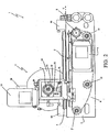
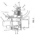
- 1 denotes in its entirety the device for rounding corners of panels in particular made of wood according to the present invention.
- the device 1 in question may be used individually or provided on complex machines for edging panels in series with other working units such as an end-butting unit, a milling unit, a sanding unit, a gluing unit, a trimming unit or other units.
- the device 1 is rested on the ground by means of a support structure 2 which may therefore be in common with that of an edging machine equipped with other working units (not shown).
- This structure 2 is provided with means for feeding a panel, in particular made of chipboard, MDF or the like (not shown), for example consisting of a tracked conveyor belt of a conventional type per se, able to cause feeding of the panels individually and in a horizontal position, in succession with respect to each other between an entrance way and an exit way of the device 1.
- a panel in particular made of chipboard, MDF or the like (not shown), for example consisting of a tracked conveyor belt of a conventional type per se, able to cause feeding of the panels individually and in a horizontal position, in succession with respect to each other between an entrance way and an exit way of the device 1.
- a mobile carriage 4 supporting a milling unit 3 is actuated so as to be displaced by a first motor 7, over a suitable displacement path S, with a direction of advancing movement Y parallel to the direction of the panel, along a guide 5 formed on the support structure 2.
- the first motor 7 (preferably a worm gearmotor) is connected to the carriage 4 by means of flexible transmission means.
- the latter advantageously consist of a chain 6 wound endlessly around a driving wheel 8, a tensioning wheel 9 and two transmission wheels 10.
- the first motor 7 advantageously consists of a normal asynchronous motor, which is therefore available on the market at a low cost.
- This motor 7 is controlled by an inverter connected to the PLC having an electronic positioning system by means of which it is possible to control the rotation of the rotor with the magnetic poles and therefore, ultimately, control the position of the carriage 4 and the milling unit 3 along the guide 5.
- the movement of the panels is assisted by an encoder which is also connected to the PLC and is able to produce a pulsed signal capable of actuating the inverter of the first motor 7 so that the carriage moves perfectly in synchronism with the panels.
- the first motor 7 causes the displacement of the milling unit at the same speed as the panels and therefore this unit in terms of this displacement may be regarded as being at a standstill with respect to the panels.
- the first motor 7 may also be provided with an encoder connected to the PLC so as to ensure a greater precision during positioning of the milling unit 3 along its displacement path S.
- Two mechanical end-of-travel safety stops 90 are in any case envisaged for limiting the displacement path of the milling unit 3.
- the milling unit 3 is rotatably mounted on the carriage 4 by means of a shaft 12, about a transverse axis X at right angles to the direction of advancing movement Y of the mobile carriage 4.
- this milling unit 3 comprises a second motor 13 with, keyed on its shaft, a milling tool 14 having a radial shape for performing a rounding operation on the corners of the edges along the panel sides.
- the form of the shape to be imparted to the corners may be of any nature according to requirements or the rounding radius of the milling tool 14.
- the milling unit 3 is operated so as to rotate about the shaft 12 with a transverse axis X by a third motor 15 integral with the carriage 4 and electrically coupled to the first motor 7 so as to synchronize, in accordance with predefined operating steps, the rotation of the milling unit 3 together with its displacement along the path S above the carriage.
- the third motor 15 consists of a worm gearmotor controlled by means of an inverter connected to the PLC and provided with a pulsed positioning device for correct angular positioning of the milling unit 3.
- this third motor 15 is provided with an encoder for ensuring greater prevision during angular positioning of the unit 3.
- first motor and/or the third motor may also be controlled by other electrical actuating systems (actuating systems for brushless motors, of the DC type, etc.), without thereby departing from the scope of claim 1.
- electrical actuating systems actuating systems for brushless motors, of the DC type, etc.
- a frontal joining device 30 and a vertical joining device 31 are advantageously envisaged, the latter consisting of an idle disk which is free to rotate with its axis parallel to the axis of the tool 14.
- Pneumatic actuators are envisaged for keeping the two joining devices 30 and 31 constantly pressed against the panel and thus ensure the correct working position of the tool 14.
- the milling unit 3 is provided with a support 40 consisting of a plate with a frontally disk-shaped form on which a milling head 42, which supports the tool 14 and the two joining devices 30 and 31, is slidably mounted along second guides 41.
- a first pneumatic actuator 50 is then mounted as shown in Figure 1 on the support 40 and is actuated by the PLC so as to move the head 42 along the second guides 41 until it pushes the vertical joining device 31 up against the bottom surface of the panel.
- This first pneumatic actuator 50 preferably operates under tensile load when it is arranged above the milling head 42 (as shown in the accompanying figures), during a first step involving machining of the front side of the panel, and is instead under no load when it is positioned underneath the milling head 42, during a second step involving machining of the rear side of the panel.
- Switching of the air between the two operating conditions of the first actuator 50 is caused by actuation of a valve 51 which is mounted on the carriage 4 behind the disk-shaped support 40 and which supports an actuating stem carrying at the top a roller 52 kept resiliently in contact with a cam 53 consisting of an eccentric part keyed directly onto the rotating shaft 12 of the milling unit 3.
- a second pneumatic actuator 60 is envisaged for displacing the milling head 42 transversely with respect to the direction of feeding X of the panel until the front joining device 30 is brought into contact against the side edge of the panel.
- a third pneumatic actuator 70 which is actuated by a special switch, is able to exclude operation of the milling unit 3.
- this third actuator 70 causes the displacement of the milling head 42 between a raised working position, where it intercepts the panel and by means of the tool 14 performs rounding of its angular profiles, and a lowered disengaged position, where it does not interfere with the horizontal displacement of the panel.
- a photocell detects the arrival of the panel, signalling its passing movement through an entrance way to the PLC which activates the milling unit 3 which causes separate following of the carriage 4 with the milling unit on top as well as rotation of the latter in accordance with the two operating steps mentioned above.
- Activation of the movement of the milling unit 3 in order to perform the second machining operation is obtained by means of a sensor connected to the PLC which detects the length of the panel and therefore is able to indicate when the latter has passed beyond the said milling unit.
- the precise safe positioning of the milling unit 3 with respect to its two possible displacement and rotational movements is ensured by a plurality of sensors consisting, for example, of proximity sensors able to detect the presence of reference points situated along the displacement path S of the milling unit 3 as well as on the disk-shaped support plate 40.
- Mechanical safety means are in any case envisaged not only for horizontal displacement (end-of-travel device 90), but also for preventing uncontrolled rotation of the milling unit greater than 360°.
- a cable-holder chain is envisaged for powering electrically the second motor 13 of the milling tool 14 and the sensors for controlling the angular position of the milling unit 3.
- the device 1 according to the invention is particularly compact, simple and inexpensive to manufacture and operationally entirely reliable.
- a further advantage of the device 1 in question is that it allows independent management of the speed of displacement and speed of rotation of the milling unit 3.
Landscapes
- Life Sciences & Earth Sciences (AREA)
- Engineering & Computer Science (AREA)
- Mechanical Engineering (AREA)
- Wood Science & Technology (AREA)
- Forests & Forestry (AREA)
- Milling Processes (AREA)
- Supplying Of Containers To The Packaging Station (AREA)
- Vehicle Body Suspensions (AREA)
- Electrophonic Musical Instruments (AREA)
- Grinding Of Cylindrical And Plane Surfaces (AREA)
- Control Of Resistance Heating (AREA)
- Replacing, Conveying, And Pick-Finding For Filamentary Materials (AREA)
Claims (11)
- Vorrichtung zum Abrunden von Plattenecken mit:einer Tragkonstruktion (2);dadurch gekennzeichnet, dass die Fräsanlage (3) derart betätigt wird, dass sie sich durch einen dritten, in den Fahrwagen integrierten Motor (15), der mit dem ersten Motor (7) elektrisch verbunden ist, mit einer Querachse (X) um die Welle dreht, so dass die Drehung der Fräsanlage (3) gemäß vorher festgelegten Arbeitsschritten mit ihrer Verschiebung über dem mobilen Fahrwagen synchronisiert wird.- einer Zuführungseinrichtung, die an der Tragkonstruktion montiert ist, und die mindestens eine Platte, die zwei Stirnseiten besitzt, mit einer kontinuierlichen Bewegung zwischen mindestens einem Eingang und mindestens einem Ausgang der Vorrichtung befördern kann;- einem mobilen Fahrwagen (4), der lenkbar an der Tragkonstruktion montiert ist, und durch einen ersten Motor (7) bewegt wird, so dass er parallel zu der Platte und gleichzeitig mit letzterer in Vorwärtsbewegung (Y) verschoben wird;- einer Fräsanlage (3), die drehbar an dem mobilen Fahrwagen um eine Welle mit einer Achse (X) quer zur Vorwärtsbewegung (Y) des Fahrwagens montiert ist, wobei die Fräsanlage einen zweiten Motor (13) besitzt, der verkeilt auf seiner Drehwelle ein Fräswerkzeug (14) zur Durchführung des Abrundens der Winkelprofile der Stirnseiten der sich vorwärts bewegenden Platte aufweist;
- Vorrichtung nach Anspruch 1, dadurch gekennzeichnet, dass der erste Motor (7) und/oder der dritte Motor (15) durch ein elektrisches Steuerungssystem gesteuert werden.
- Vorrichtung nach Anspruch 2, dadurch gekennzeichnet, dass der erste Motor (7) durch einen Wechselrichter gesteuert wird.
- Vorrichtung nach Anspruch 2, dadurch gekennzeichnet, dass der dritte Motor (15) durch einen Wechselrichter gesteuert wird.
- Vorrichtung nach einem der vorhergehenden Ansprüche, dadurch gekennzeichnet, dass der erste und/oder der dritte Motor (7, 15) mit einem Wechselrichter ausgestattet sind.
- Vorrichtung nach Anspruch 1, dadurch gekennzeichnet, dass die Fräsanlage mindestens eine frontale Verbindungsvorrichtung (30) und mindestens eine vertikale Verbindungsvorrichtung (31) besitzt.
- Vorrichtung nach Anspruch 6, dadurch gekennzeichnet, dass die Fräsanlage (3) folgendes aufweist:- eine Auflage (40), auf der ein Fräskopf (42), der das Fräswerkzeug und die Verbindungsvorrichtungen hält, entlang zweiten Führungen (41) verschiebbar montiert ist;- einen ersten pneumatischen Stellantrieb (50), der an der Auflage montiert ist, und den Kopf (42) den zweiten Führungen entlang verschieben kann, so dass die vertikale Verbindungsvorrichtung (31) konstant gegen die Platte gedrückt wird.
- Vorrichtung nach Anspruch 7, dadurch gekennzeichnet, dass der erste pneumatische Stellantrieb (50) unter Zugbelastung arbeitet, wenn er über dem Fräskopf (42) angeordnet ist, und keiner Belastung unterworfen ist, wenn er sich unter dem Fräskopf befindet.
- Vorrichtung nach Anspruch 8, dadurch gekennzeichnet, dass sie ein Ventil (51) besitzt, das an dem Fahrwagen (4) montiert ist, und durch einen Nocken (53) betätigt wird, der mit der Welle (12) der Fräsanlage verkeilt ist, und den Druck des ersten pneumatischen Stellantriebes (50) aktivieren kann.
- Vorrichtung nach Anspruch 6, dadurch gekennzeichnet, dass die Fräsanlage folgendes besitzt:- eine Auflage (40), auf der ein Fräskopf (42), der das Fräswerkzeug und die Verbindungsvorrichtungen hält, entlang zweiten Führungen verschiebbar montiert ist;- einen zweiten pneumatischen Stellantrieb (60), der an der Auflage montiert ist, und den Kopf quer zu der Zuführungsrichtung der Platte verschieben kann, so dass die frontale Verbindungsvorrichtung konstant gegen die Platte gedrückt wird.
- Vorrichtung nach Anspruch 1, dadurch gekennzeichnet, dass die Fräsanlage einen dritten pneumatischen Stellantrieb (70) besitzt, der den Fräskopf (42) zwischen einer Arbeitsposition, in der er die Platte abfängt, und das Abrunden der Winkelprofile ihrer Stirnseiten mittels des Fräswerkzeuges durchführt, und einer ausgekoppelten Position, in der die Platte den Fräskopf nicht abfängt, verschieben kann.
Applications Claiming Priority (1)
| Application Number | Priority Date | Filing Date | Title |
|---|---|---|---|
| IT000120A ITPD20050120A1 (it) | 2005-05-02 | 2005-05-02 | Dispositivo per l'arrotondatura angolare di pannelli |
Publications (2)
| Publication Number | Publication Date |
|---|---|
| EP1719594A1 EP1719594A1 (de) | 2006-11-08 |
| EP1719594B1 true EP1719594B1 (de) | 2008-06-18 |
Family
ID=36781524
Family Applications (1)
| Application Number | Title | Priority Date | Filing Date |
|---|---|---|---|
| EP06075945A Expired - Lifetime EP1719594B1 (de) | 2005-05-02 | 2006-04-24 | Vorrichtung zum Abrunden von Plattenecken |
Country Status (4)
| Country | Link |
|---|---|
| EP (1) | EP1719594B1 (de) |
| AT (1) | ATE398515T1 (de) |
| DE (1) | DE602006001485D1 (de) |
| IT (1) | ITPD20050120A1 (de) |
Families Citing this family (3)
| Publication number | Priority date | Publication date | Assignee | Title |
|---|---|---|---|---|
| CA2873316C (en) * | 2006-09-11 | 2017-04-18 | Unilin, Bvba | Covering panel with bevelled edges having varying cross-section, and apparatus and method of making the same |
| IT1399939B1 (it) | 2010-04-30 | 2013-05-09 | Fravol Exp Srl | Utensile fresatore con profilo perfezionato per l'arrotondatura angolare di bordi di pannelli |
| PL3294507T3 (pl) * | 2015-05-11 | 2020-01-31 | Ulmadan-R.D. Aps | Sposób ciągłej obróbki krawędzi płyt i urządzenie do obróbki krawędzi |
Family Cites Families (3)
| Publication number | Priority date | Publication date | Assignee | Title |
|---|---|---|---|---|
| NL165401C (nl) * | 1977-01-06 | 1981-04-15 | Helmes Maschf Bv | Machine voor het frezen van een pen aan het kopse uiteinde van een houten werkstuk en werkwijze voor het bedrijven van deze machine. |
| DE4408596A1 (de) * | 1994-03-15 | 1995-09-21 | Reich Spezialmaschinen Gmbh | Kantenanleimmaschine mit einer Fräsvorrichtung |
| IT1314019B1 (it) * | 1999-11-09 | 2002-12-03 | Fravol Exp S R L | Macchina bordatrice automatica, perfezionata. |
-
2005
- 2005-05-02 IT IT000120A patent/ITPD20050120A1/it unknown
-
2006
- 2006-04-24 AT AT06075945T patent/ATE398515T1/de active
- 2006-04-24 DE DE602006001485T patent/DE602006001485D1/de not_active Expired - Lifetime
- 2006-04-24 EP EP06075945A patent/EP1719594B1/de not_active Expired - Lifetime
Also Published As
| Publication number | Publication date |
|---|---|
| DE602006001485D1 (de) | 2008-07-31 |
| EP1719594A1 (de) | 2006-11-08 |
| ATE398515T1 (de) | 2008-07-15 |
| ITPD20050120A1 (it) | 2006-11-03 |
Similar Documents
| Publication | Publication Date | Title |
|---|---|---|
| CN103692311B (zh) | 全自动卧式玻璃直线四边磨边机及其磨边加工方法 | |
| US4243081A (en) | Automatic apparatus for machining panels, planks and similar articles made of wood, wooden derivatives and the like | |
| EP2998088B1 (de) | Arbeitsstation einer Maschine für Steinplatten, Marmor, Kunststoff, oder dergleichen, mit einer Opfermaterialarbeitsebene | |
| CN201483618U (zh) | 全自动异形封边修边机 | |
| KR20170078686A (ko) | 수직으로 배치되는 유리판을 자동적으로 드릴링하고 밀링하기 위한 자동 기계 및 방법 | |
| EP2845840B1 (de) | Vorrichung und verfahren zum schneiden von verbundenen gasscheiben | |
| CN101687335A (zh) | 用于加工镶板的侧边缘的方法和用于执行该方法的装置 | |
| JPH09510147A (ja) | フライス削り装置を備えた縁部接着装置 | |
| EP3248745B1 (de) | Kantenanleimmaschine mit einer fräsvorrichtung und betriebsverfahren der kantenanleimmaschine | |
| CN103707153B (zh) | 玻璃磨边机及其磨边加工方法 | |
| CN203853884U (zh) | 磨头组件及玻璃磨边机 | |
| EP1719594B1 (de) | Vorrichtung zum Abrunden von Plattenecken | |
| CN102699686B (zh) | 一种开槽弯字机 | |
| JPH06218702A (ja) | 連続して移動する板状加工物の端部加工用装置 | |
| CA2475250C (en) | Apparatus for cutting and nibbling a sheet metal in coil form | |
| JP2009527367A (ja) | 形削り盤 | |
| EP3632614B1 (de) | Geradlinige schleifmaschine | |
| US6607069B2 (en) | Crank drive for returning work pieces | |
| EP1772238B1 (de) | Vorrichtung zur Fertigbearbeitung von an Platten angebrachten Metallkanten | |
| JP2020514092A (ja) | 棒状の被加工物、例えば窓用形材または扉用形材を加工するための装置 | |
| JPH0286402A (ja) | 板材の加工機 | |
| ITMO20100054A1 (it) | Macchina per il taglio di elementi lastriformi, particolarmente per il taglio di piastrelle ceramiche, pietre naturali e simili | |
| EP4684912A1 (de) | Vorrichtung und verfahren zum trimmen von keramikpulverartikeln | |
| EP1099523B1 (de) | Automatische Vorrichtung zur Bildung von Rändern | |
| CN210255472U (zh) | 一种数控节能液压切边、整形机 |
Legal Events
| Date | Code | Title | Description |
|---|---|---|---|
| PUAI | Public reference made under article 153(3) epc to a published international application that has entered the european phase |
Free format text: ORIGINAL CODE: 0009012 |
|
| AK | Designated contracting states |
Kind code of ref document: A1 Designated state(s): AT BE BG CH CY CZ DE DK EE ES FI FR GB GR HU IE IS IT LI LT LU LV MC NL PL PT RO SE SI SK TR |
|
| AX | Request for extension of the european patent |
Extension state: AL BA HR MK YU |
|
| RAP1 | Party data changed (applicant data changed or rights of an application transferred) |
Owner name: FRAVOL EXPORT S.R.L. |
|
| 17P | Request for examination filed |
Effective date: 20070201 |
|
| AKX | Designation fees paid |
Designated state(s): AT BE BG CH CY CZ DE DK EE ES FI FR GB GR HU IE IS IT LI LT LU LV MC NL PL PT RO SE SI SK TR |
|
| GRAP | Despatch of communication of intention to grant a patent |
Free format text: ORIGINAL CODE: EPIDOSNIGR1 |
|
| GRAS | Grant fee paid |
Free format text: ORIGINAL CODE: EPIDOSNIGR3 |
|
| GRAA | (expected) grant |
Free format text: ORIGINAL CODE: 0009210 |
|
| RAP1 | Party data changed (applicant data changed or rights of an application transferred) |
Owner name: FRAVOL EXPORT S.R.L. |
|
| AK | Designated contracting states |
Kind code of ref document: B1 Designated state(s): AT BE BG CH CY CZ DE DK EE ES FI FR GB GR HU IE IS IT LI LT LU LV MC NL PL PT RO SE SI SK TR |
|
| REG | Reference to a national code |
Ref country code: GB Ref legal event code: FG4D |
|
| REF | Corresponds to: |
Ref document number: 602006001485 Country of ref document: DE Date of ref document: 20080731 Kind code of ref document: P |
|
| REG | Reference to a national code |
Ref country code: CH Ref legal event code: EP |
|
| REG | Reference to a national code |
Ref country code: IE Ref legal event code: FG4D |
|
| PG25 | Lapsed in a contracting state [announced via postgrant information from national office to epo] |
Ref country code: FI Free format text: LAPSE BECAUSE OF FAILURE TO SUBMIT A TRANSLATION OF THE DESCRIPTION OR TO PAY THE FEE WITHIN THE PRESCRIBED TIME-LIMIT Effective date: 20080618 Ref country code: SI Free format text: LAPSE BECAUSE OF FAILURE TO SUBMIT A TRANSLATION OF THE DESCRIPTION OR TO PAY THE FEE WITHIN THE PRESCRIBED TIME-LIMIT Effective date: 20080618 |
|
| PG25 | Lapsed in a contracting state [announced via postgrant information from national office to epo] |
Ref country code: PL Free format text: LAPSE BECAUSE OF FAILURE TO SUBMIT A TRANSLATION OF THE DESCRIPTION OR TO PAY THE FEE WITHIN THE PRESCRIBED TIME-LIMIT Effective date: 20080618 Ref country code: LV Free format text: LAPSE BECAUSE OF FAILURE TO SUBMIT A TRANSLATION OF THE DESCRIPTION OR TO PAY THE FEE WITHIN THE PRESCRIBED TIME-LIMIT Effective date: 20080618 Ref country code: NL Free format text: LAPSE BECAUSE OF FAILURE TO SUBMIT A TRANSLATION OF THE DESCRIPTION OR TO PAY THE FEE WITHIN THE PRESCRIBED TIME-LIMIT Effective date: 20080618 |
|
| NLV1 | Nl: lapsed or annulled due to failure to fulfill the requirements of art. 29p and 29m of the patents act | ||
| PG25 | Lapsed in a contracting state [announced via postgrant information from national office to epo] |
Ref country code: CZ Free format text: LAPSE BECAUSE OF FAILURE TO SUBMIT A TRANSLATION OF THE DESCRIPTION OR TO PAY THE FEE WITHIN THE PRESCRIBED TIME-LIMIT Effective date: 20080618 Ref country code: LT Free format text: LAPSE BECAUSE OF FAILURE TO SUBMIT A TRANSLATION OF THE DESCRIPTION OR TO PAY THE FEE WITHIN THE PRESCRIBED TIME-LIMIT Effective date: 20080618 Ref country code: SE Free format text: LAPSE BECAUSE OF FAILURE TO SUBMIT A TRANSLATION OF THE DESCRIPTION OR TO PAY THE FEE WITHIN THE PRESCRIBED TIME-LIMIT Effective date: 20080918 Ref country code: IS Free format text: LAPSE BECAUSE OF FAILURE TO SUBMIT A TRANSLATION OF THE DESCRIPTION OR TO PAY THE FEE WITHIN THE PRESCRIBED TIME-LIMIT Effective date: 20081018 |
|
| PG25 | Lapsed in a contracting state [announced via postgrant information from national office to epo] |
Ref country code: ES Free format text: LAPSE BECAUSE OF FAILURE TO SUBMIT A TRANSLATION OF THE DESCRIPTION OR TO PAY THE FEE WITHIN THE PRESCRIBED TIME-LIMIT Effective date: 20080929 Ref country code: BE Free format text: LAPSE BECAUSE OF FAILURE TO SUBMIT A TRANSLATION OF THE DESCRIPTION OR TO PAY THE FEE WITHIN THE PRESCRIBED TIME-LIMIT Effective date: 20080618 Ref country code: RO Free format text: LAPSE BECAUSE OF FAILURE TO SUBMIT A TRANSLATION OF THE DESCRIPTION OR TO PAY THE FEE WITHIN THE PRESCRIBED TIME-LIMIT Effective date: 20080618 Ref country code: PT Free format text: LAPSE BECAUSE OF FAILURE TO SUBMIT A TRANSLATION OF THE DESCRIPTION OR TO PAY THE FEE WITHIN THE PRESCRIBED TIME-LIMIT Effective date: 20081118 Ref country code: SK Free format text: LAPSE BECAUSE OF FAILURE TO SUBMIT A TRANSLATION OF THE DESCRIPTION OR TO PAY THE FEE WITHIN THE PRESCRIBED TIME-LIMIT Effective date: 20080618 |
|
| PLBE | No opposition filed within time limit |
Free format text: ORIGINAL CODE: 0009261 |
|
| STAA | Information on the status of an ep patent application or granted ep patent |
Free format text: STATUS: NO OPPOSITION FILED WITHIN TIME LIMIT |
|
| PG25 | Lapsed in a contracting state [announced via postgrant information from national office to epo] |
Ref country code: DK Free format text: LAPSE BECAUSE OF FAILURE TO SUBMIT A TRANSLATION OF THE DESCRIPTION OR TO PAY THE FEE WITHIN THE PRESCRIBED TIME-LIMIT Effective date: 20080618 Ref country code: BG Free format text: LAPSE BECAUSE OF FAILURE TO SUBMIT A TRANSLATION OF THE DESCRIPTION OR TO PAY THE FEE WITHIN THE PRESCRIBED TIME-LIMIT Effective date: 20080918 Ref country code: EE Free format text: LAPSE BECAUSE OF FAILURE TO SUBMIT A TRANSLATION OF THE DESCRIPTION OR TO PAY THE FEE WITHIN THE PRESCRIBED TIME-LIMIT Effective date: 20080618 |
|
| 26N | No opposition filed |
Effective date: 20090319 |
|
| REG | Reference to a national code |
Ref country code: FR Ref legal event code: ST Effective date: 20091231 |
|
| PG25 | Lapsed in a contracting state [announced via postgrant information from national office to epo] |
Ref country code: IE Free format text: LAPSE BECAUSE OF NON-PAYMENT OF DUE FEES Effective date: 20090424 Ref country code: FR Free format text: LAPSE BECAUSE OF NON-PAYMENT OF DUE FEES Effective date: 20091222 Ref country code: MC Free format text: LAPSE BECAUSE OF NON-PAYMENT OF DUE FEES Effective date: 20090430 |
|
| PG25 | Lapsed in a contracting state [announced via postgrant information from national office to epo] |
Ref country code: GR Free format text: LAPSE BECAUSE OF FAILURE TO SUBMIT A TRANSLATION OF THE DESCRIPTION OR TO PAY THE FEE WITHIN THE PRESCRIBED TIME-LIMIT Effective date: 20080919 |
|
| REG | Reference to a national code |
Ref country code: CH Ref legal event code: PL |
|
| GBPC | Gb: european patent ceased through non-payment of renewal fee |
Effective date: 20100424 |
|
| PG25 | Lapsed in a contracting state [announced via postgrant information from national office to epo] |
Ref country code: CH Free format text: LAPSE BECAUSE OF NON-PAYMENT OF DUE FEES Effective date: 20100430 Ref country code: LI Free format text: LAPSE BECAUSE OF NON-PAYMENT OF DUE FEES Effective date: 20100430 |
|
| PG25 | Lapsed in a contracting state [announced via postgrant information from national office to epo] |
Ref country code: GB Free format text: LAPSE BECAUSE OF NON-PAYMENT OF DUE FEES Effective date: 20100424 |
|
| PG25 | Lapsed in a contracting state [announced via postgrant information from national office to epo] |
Ref country code: LU Free format text: LAPSE BECAUSE OF NON-PAYMENT OF DUE FEES Effective date: 20090424 |
|
| PG25 | Lapsed in a contracting state [announced via postgrant information from national office to epo] |
Ref country code: HU Free format text: LAPSE BECAUSE OF FAILURE TO SUBMIT A TRANSLATION OF THE DESCRIPTION OR TO PAY THE FEE WITHIN THE PRESCRIBED TIME-LIMIT Effective date: 20081219 |
|
| PG25 | Lapsed in a contracting state [announced via postgrant information from national office to epo] |
Ref country code: TR Free format text: LAPSE BECAUSE OF FAILURE TO SUBMIT A TRANSLATION OF THE DESCRIPTION OR TO PAY THE FEE WITHIN THE PRESCRIBED TIME-LIMIT Effective date: 20080618 |
|
| PG25 | Lapsed in a contracting state [announced via postgrant information from national office to epo] |
Ref country code: CY Free format text: LAPSE BECAUSE OF FAILURE TO SUBMIT A TRANSLATION OF THE DESCRIPTION OR TO PAY THE FEE WITHIN THE PRESCRIBED TIME-LIMIT Effective date: 20080618 |
|
| P01 | Opt-out of the competence of the unified patent court (upc) registered |
Effective date: 20230302 |
|
| PGFP | Annual fee paid to national office [announced via postgrant information from national office to epo] |
Ref country code: DE Payment date: 20250422 Year of fee payment: 20 |
|
| PGFP | Annual fee paid to national office [announced via postgrant information from national office to epo] |
Ref country code: IT Payment date: 20250328 Year of fee payment: 20 |
|
| PGFP | Annual fee paid to national office [announced via postgrant information from national office to epo] |
Ref country code: AT Payment date: 20250423 Year of fee payment: 20 |