EP1719603A2 - Commande d'un procédé de fabrication de profilés extrudés - Google Patents
Commande d'un procédé de fabrication de profilés extrudés Download PDFInfo
- Publication number
- EP1719603A2 EP1719603A2 EP06113408A EP06113408A EP1719603A2 EP 1719603 A2 EP1719603 A2 EP 1719603A2 EP 06113408 A EP06113408 A EP 06113408A EP 06113408 A EP06113408 A EP 06113408A EP 1719603 A2 EP1719603 A2 EP 1719603A2
- Authority
- EP
- European Patent Office
- Prior art keywords
- scale
- production process
- horizon
- scale arms
- arms
- Prior art date
- Legal status (The legal status is an assumption and is not a legal conclusion. Google has not performed a legal analysis and makes no representation as to the accuracy of the status listed.)
- Granted
Links
Images







Classifications
-
- G—PHYSICS
- G05—CONTROLLING; REGULATING
- G05B—CONTROL OR REGULATING SYSTEMS IN GENERAL; FUNCTIONAL ELEMENTS OF SUCH SYSTEMS; MONITORING OR TESTING ARRANGEMENTS FOR SUCH SYSTEMS OR ELEMENTS
- G05B19/00—Program-control systems
- G05B19/02—Program-control systems electric
- G05B19/18—Numerical control [NC], i.e. automatically operating machines, in particular machine tools, e.g. in a manufacturing environment, so as to execute positioning, movement or co-ordinated operations by means of program data in numerical form
- G05B19/409—Numerical control [NC], i.e. automatically operating machines, in particular machine tools, e.g. in a manufacturing environment, so as to execute positioning, movement or co-ordinated operations by means of program data in numerical form characterised by using manual data input [MDI] or by using control panel, e.g. controlling functions with the panel; characterised by control panel details or by setting parameters
-
- B—PERFORMING OPERATIONS; TRANSPORTING
- B29—WORKING OF PLASTICS; WORKING OF SUBSTANCES IN A PLASTIC STATE IN GENERAL
- B29C—SHAPING OR JOINING OF PLASTICS; SHAPING OF MATERIAL IN A PLASTIC STATE, NOT OTHERWISE PROVIDED FOR; AFTER-TREATMENT OF THE SHAPED PRODUCTS, e.g. REPAIRING
- B29C48/00—Extrusion moulding, i.e. expressing the moulding material through a die or nozzle which imparts the desired form; Apparatus therefor
- B29C48/03—Extrusion moulding, i.e. expressing the moulding material through a die or nozzle which imparts the desired form; Apparatus therefor characterised by the shape of the extruded material at extrusion
- B29C48/05—Filamentary, e.g. strands
-
- B—PERFORMING OPERATIONS; TRANSPORTING
- B29—WORKING OF PLASTICS; WORKING OF SUBSTANCES IN A PLASTIC STATE IN GENERAL
- B29C—SHAPING OR JOINING OF PLASTICS; SHAPING OF MATERIAL IN A PLASTIC STATE, NOT OTHERWISE PROVIDED FOR; AFTER-TREATMENT OF THE SHAPED PRODUCTS, e.g. REPAIRING
- B29C48/00—Extrusion moulding, i.e. expressing the moulding material through a die or nozzle which imparts the desired form; Apparatus therefor
- B29C48/25—Component parts, details or accessories; Auxiliary operations
- B29C48/92—Measuring, controlling or regulating
-
- B—PERFORMING OPERATIONS; TRANSPORTING
- B29—WORKING OF PLASTICS; WORKING OF SUBSTANCES IN A PLASTIC STATE IN GENERAL
- B29C—SHAPING OR JOINING OF PLASTICS; SHAPING OF MATERIAL IN A PLASTIC STATE, NOT OTHERWISE PROVIDED FOR; AFTER-TREATMENT OF THE SHAPED PRODUCTS, e.g. REPAIRING
- B29C2948/00—Indexing scheme relating to extrusion moulding
- B29C2948/92—Measuring, controlling or regulating
- B29C2948/92504—Controlled parameter
- B29C2948/92514—Pressure
-
- B—PERFORMING OPERATIONS; TRANSPORTING
- B29—WORKING OF PLASTICS; WORKING OF SUBSTANCES IN A PLASTIC STATE IN GENERAL
- B29C—SHAPING OR JOINING OF PLASTICS; SHAPING OF MATERIAL IN A PLASTIC STATE, NOT OTHERWISE PROVIDED FOR; AFTER-TREATMENT OF THE SHAPED PRODUCTS, e.g. REPAIRING
- B29C2948/00—Indexing scheme relating to extrusion moulding
- B29C2948/92—Measuring, controlling or regulating
- B29C2948/92504—Controlled parameter
- B29C2948/9258—Velocity
- B29C2948/9259—Angular velocity
-
- B—PERFORMING OPERATIONS; TRANSPORTING
- B29—WORKING OF PLASTICS; WORKING OF SUBSTANCES IN A PLASTIC STATE IN GENERAL
- B29C—SHAPING OR JOINING OF PLASTICS; SHAPING OF MATERIAL IN A PLASTIC STATE, NOT OTHERWISE PROVIDED FOR; AFTER-TREATMENT OF THE SHAPED PRODUCTS, e.g. REPAIRING
- B29C2948/00—Indexing scheme relating to extrusion moulding
- B29C2948/92—Measuring, controlling or regulating
- B29C2948/92504—Controlled parameter
- B29C2948/9258—Velocity
- B29C2948/926—Flow or feed rate
-
- B—PERFORMING OPERATIONS; TRANSPORTING
- B29—WORKING OF PLASTICS; WORKING OF SUBSTANCES IN A PLASTIC STATE IN GENERAL
- B29C—SHAPING OR JOINING OF PLASTICS; SHAPING OF MATERIAL IN A PLASTIC STATE, NOT OTHERWISE PROVIDED FOR; AFTER-TREATMENT OF THE SHAPED PRODUCTS, e.g. REPAIRING
- B29C2948/00—Indexing scheme relating to extrusion moulding
- B29C2948/92—Measuring, controlling or regulating
- B29C2948/92504—Controlled parameter
- B29C2948/92609—Dimensions
-
- B—PERFORMING OPERATIONS; TRANSPORTING
- B29—WORKING OF PLASTICS; WORKING OF SUBSTANCES IN A PLASTIC STATE IN GENERAL
- B29C—SHAPING OR JOINING OF PLASTICS; SHAPING OF MATERIAL IN A PLASTIC STATE, NOT OTHERWISE PROVIDED FOR; AFTER-TREATMENT OF THE SHAPED PRODUCTS, e.g. REPAIRING
- B29C2948/00—Indexing scheme relating to extrusion moulding
- B29C2948/92—Measuring, controlling or regulating
- B29C2948/92504—Controlled parameter
- B29C2948/92704—Temperature
-
- B—PERFORMING OPERATIONS; TRANSPORTING
- B29—WORKING OF PLASTICS; WORKING OF SUBSTANCES IN A PLASTIC STATE IN GENERAL
- B29C—SHAPING OR JOINING OF PLASTICS; SHAPING OF MATERIAL IN A PLASTIC STATE, NOT OTHERWISE PROVIDED FOR; AFTER-TREATMENT OF THE SHAPED PRODUCTS, e.g. REPAIRING
- B29C2948/00—Indexing scheme relating to extrusion moulding
- B29C2948/92—Measuring, controlling or regulating
- B29C2948/92819—Location or phase of control
- B29C2948/92857—Extrusion unit
- B29C2948/92876—Feeding, melting, plasticising or pumping zones, e.g. the melt itself
- B29C2948/92885—Screw or gear
-
- B—PERFORMING OPERATIONS; TRANSPORTING
- B29—WORKING OF PLASTICS; WORKING OF SUBSTANCES IN A PLASTIC STATE IN GENERAL
- B29C—SHAPING OR JOINING OF PLASTICS; SHAPING OF MATERIAL IN A PLASTIC STATE, NOT OTHERWISE PROVIDED FOR; AFTER-TREATMENT OF THE SHAPED PRODUCTS, e.g. REPAIRING
- B29C2948/00—Indexing scheme relating to extrusion moulding
- B29C2948/92—Measuring, controlling or regulating
- B29C2948/92819—Location or phase of control
- B29C2948/92857—Extrusion unit
- B29C2948/92876—Feeding, melting, plasticising or pumping zones, e.g. the melt itself
- B29C2948/92895—Barrel or housing
-
- B—PERFORMING OPERATIONS; TRANSPORTING
- B29—WORKING OF PLASTICS; WORKING OF SUBSTANCES IN A PLASTIC STATE IN GENERAL
- B29C—SHAPING OR JOINING OF PLASTICS; SHAPING OF MATERIAL IN A PLASTIC STATE, NOT OTHERWISE PROVIDED FOR; AFTER-TREATMENT OF THE SHAPED PRODUCTS, e.g. REPAIRING
- B29C2948/00—Indexing scheme relating to extrusion moulding
- B29C2948/92—Measuring, controlling or regulating
- B29C2948/92819—Location or phase of control
- B29C2948/92857—Extrusion unit
- B29C2948/92904—Die; Nozzle zone
-
- B—PERFORMING OPERATIONS; TRANSPORTING
- B29—WORKING OF PLASTICS; WORKING OF SUBSTANCES IN A PLASTIC STATE IN GENERAL
- B29C—SHAPING OR JOINING OF PLASTICS; SHAPING OF MATERIAL IN A PLASTIC STATE, NOT OTHERWISE PROVIDED FOR; AFTER-TREATMENT OF THE SHAPED PRODUCTS, e.g. REPAIRING
- B29C2948/00—Indexing scheme relating to extrusion moulding
- B29C2948/92—Measuring, controlling or regulating
- B29C2948/92819—Location or phase of control
- B29C2948/92923—Calibration, after-treatment or cooling zone
-
- B—PERFORMING OPERATIONS; TRANSPORTING
- B29—WORKING OF PLASTICS; WORKING OF SUBSTANCES IN A PLASTIC STATE IN GENERAL
- B29C—SHAPING OR JOINING OF PLASTICS; SHAPING OF MATERIAL IN A PLASTIC STATE, NOT OTHERWISE PROVIDED FOR; AFTER-TREATMENT OF THE SHAPED PRODUCTS, e.g. REPAIRING
- B29C2948/00—Indexing scheme relating to extrusion moulding
- B29C2948/92—Measuring, controlling or regulating
- B29C2948/92819—Location or phase of control
- B29C2948/92971—Fluids, e.g. for temperature control or of environment
-
- B—PERFORMING OPERATIONS; TRANSPORTING
- B29—WORKING OF PLASTICS; WORKING OF SUBSTANCES IN A PLASTIC STATE IN GENERAL
- B29C—SHAPING OR JOINING OF PLASTICS; SHAPING OF MATERIAL IN A PLASTIC STATE, NOT OTHERWISE PROVIDED FOR; AFTER-TREATMENT OF THE SHAPED PRODUCTS, e.g. REPAIRING
- B29C48/00—Extrusion moulding, i.e. expressing the moulding material through a die or nozzle which imparts the desired form; Apparatus therefor
- B29C48/03—Extrusion moulding, i.e. expressing the moulding material through a die or nozzle which imparts the desired form; Apparatus therefor characterised by the shape of the extruded material at extrusion
- B29C48/07—Flat, e.g. panels
-
- B—PERFORMING OPERATIONS; TRANSPORTING
- B29—WORKING OF PLASTICS; WORKING OF SUBSTANCES IN A PLASTIC STATE IN GENERAL
- B29C—SHAPING OR JOINING OF PLASTICS; SHAPING OF MATERIAL IN A PLASTIC STATE, NOT OTHERWISE PROVIDED FOR; AFTER-TREATMENT OF THE SHAPED PRODUCTS, e.g. REPAIRING
- B29C48/00—Extrusion moulding, i.e. expressing the moulding material through a die or nozzle which imparts the desired form; Apparatus therefor
- B29C48/03—Extrusion moulding, i.e. expressing the moulding material through a die or nozzle which imparts the desired form; Apparatus therefor characterised by the shape of the extruded material at extrusion
- B29C48/09—Articles with cross-sections having partially or fully enclosed cavities, e.g. pipes or channels
-
- G—PHYSICS
- G05—CONTROLLING; REGULATING
- G05B—CONTROL OR REGULATING SYSTEMS IN GENERAL; FUNCTIONAL ELEMENTS OF SUCH SYSTEMS; MONITORING OR TESTING ARRANGEMENTS FOR SUCH SYSTEMS OR ELEMENTS
- G05B2219/00—Program-control systems
- G05B2219/30—Nc systems
- G05B2219/35—Nc in input of data, input till input file format
- G05B2219/35507—Spider, radar, parallel axes, multivariate plot
-
- G—PHYSICS
- G05—CONTROLLING; REGULATING
- G05B—CONTROL OR REGULATING SYSTEMS IN GENERAL; FUNCTIONAL ELEMENTS OF SUCH SYSTEMS; MONITORING OR TESTING ARRANGEMENTS FOR SUCH SYSTEMS OR ELEMENTS
- G05B2219/00—Program-control systems
- G05B2219/30—Nc systems
- G05B2219/45—Nc applications
- G05B2219/45204—Die, mould making
Definitions
- the invention relates to a method for influencing a working process, ie a manufacturing and working process. Also affected by the invention is a working device with which these processes or this process can be influenced, in the form of a display representation (claim 1, claim 2).
- a working process means a production process for a particularly part-box-shaped extrusion component, such as a cable channel made of extruded plastic.
- Cable ducts are extruded components that are extruded as a profiled continuous product and cut into individual pieces after the extrusion process.
- the control of such processes is complex, as well as the large number of influencing factors that can influence this process.
- the extruded component such as the cable channel, as a profiled U-shaped structure made of a thermoplastic material.
- the PVC extruded cable channels have an outstanding position within the scope of the invention.
- the known solution methods do not make it possible to simultaneously make the control or control of the process dependent on a multiplicity of parameters and, at the same time, to take this multiplicity of parameters into consideration.
- the object of the invention is to equip a process control and the extruded and then isolated cable channel originating from this working and production process with a more global view of a multiplicity of setting parameters and result parameters. It should be a higher-level possibility of setting, presetting, monitoring, control, modification, optimization, sample preparation and analysis possible, unlike that with singular programs and singular controls so far possible.
- the invention proposes to carry out a technical process influencing on the basis of the aforementioned plurality of parameters.
- the method for the production (claim 1) works with at least three scale arms, which offer the said possibilities of influencing the process and thus allow and enable it. At least one result size scale arm and at least two independent setpoint scale arms are used. These are thus displayed on a display device, ie a display, a monitor or a machine screen, in such a way that they are able to effectively open up a horizon to the user, which facilitates and expands the process control.
- a display device ie a display, a monitor or a machine screen
- the "elongated extrusion member” hereinafter as the cross-section at least partially box-shaped, elongated cable channel, in particular with a virtually open top side, a practically closed elongated, box-shaped in cross-section cable channel or an elongated cover plate for Closing to understand the open deck side of the partially box-shaped cable channel.
- This variety of terms is used synonymously for the "elongated extrusion component” without repeating these variants in each case with OR alternatives.
- the physical quantities are defined as qualitative or quantitative information (claim 10). Among these data are physical units, such as temperature, pressure of the production process or height or width of the elongated extrusion component (claim 11). Among these physical quantities may also be qualitative statements that give general information about the state of a physical variable, with regard to moisture, for example, information such as 'dry', 'standard' and 'wet' or the extrusion component itself information such as 'high' , 'Flat' or 'normal' (claim 12).
- the scale arms so numbered do not lie on top of each other, are spaced apart from one another and have an orientation that is oriented divergently at least in the case of two of these at least three scale arms. In a production process, a large number of more scale arms will generally be present than the mentioned minimum number of three scale arms, of which at least two setting variables represent.
- An adjustment variable is to be understood as a variable that can be predetermined by an adjustment in the production process. It then occurs in the process, or it is measurable in it. There is an immediate causality between the specification of this set value and the sequence in the production process.
- the setting variables-scale arms for the extruding production process represent at least two non-identical and also non-linear-dependent process variables of the production process (claims 15, 16).
- this result variable is not necessarily only to be read on the product, but it can also be a process variable of the work process.
- this measure of the result represents the size of a wall (thickness, dimension) or the viscosity of the melt with which the extrusion component is produced, or the result size represents a temperature which arises in the course of the extruding production process, for example the melt temperature.
- the melt temperature is the temperature in an extrusion process that possesses the melt from which the continuous extrusion component is made.
- the scale arms mentioned those which represent result quantities and those which represent setting values, are called “categories".
- the scale arms of the category “result size” are to be understood as all those scale arms in a method or a display representation which carry result sizes as a numbering or scaling.
- the scale arms of the category of setting variables includes all those scale arms which carry setting variables in their scaling.
- the above sizes may be qualitative or quantitative information according to the above explanation (claims 10, 11 and 12).
- the three mentioned scale arms which would at least have to be present in order to enable a horizontal clamping, are preferably clamped in two dimensions by the presentation device.
- a control horizon is created on the screen (the display), which allows the process control to be simple, clear and with a large number of physical variables in the field of view for a user.
- a first horizon is drawn over the three scale arms, they form the skeleton or scaffolding for this horizon, which will visually stand out against an inner and an outer environment.
- this optical distinction is directly visible through a contrasting representation of the interior within the horizon and the inner and the outer environment.
- the plurality of (at least three) scale arms are present, and the frame predefined by them, the skeleton or frame, which allows the span of the horizon. This is possible in at least two different ways (claim 3, 4 and alternatively claim 5).
- the contrasting of the first horizon can be done so that the stored in a process computer (a data storage of a database) characteristic values of a variety of production processes are all applied together on the available (currently shown) scale arms.
- a process is depicted in such a way that it has a multiplicity of characteristic values which are arranged in such a way that each of these physical characteristics is assigned to one of the scales.
- a combination of all characteristic values then yields a line body, preferably a flat polygon, which is connected by a combination of all the points / values which are on the axes are formed arises. This polygon defines a status of the process and also includes part sizes, not just process variables.
- the "related characteristic values" described here are those which describe a status of the production process and / or extrusion component (actually the entire extrusion installation), in particular define it with repeat accuracy.
- This multitude of superimposed line bodies defines the first horizon (the primary horizon), which is thereby emphasized in contrast. This is meant to be effective (to the user or viewer).
- the respective polygons are all present within the horizon, and the outer boundary lines of the horizon do not coherently define a line body, but can have characteristic values on the individual scale arms from different line bodies; in detail the meaning and production of such a horizon in WO-A 2004/093971 (Fraunhofer) or WO-A 2003/038725 (Fraunhofer) there in the application for an IMRT with the horizon according to the local figures 5 to 10.
- a further category can be added to the at least two categories as result variables and setting variables (claim 14).
- This category complements and extends the scope of the claimed invention by also taking into account disturbances, such as external air pressure, air temperature, humidity or draft, which are capable of adversely affecting the process and / or component.
- Their consideration does not depend deterministically on setting values, ie is not directly caused or caused by a setting of a set value, but can also arise indirectly as a result of a setting.
- Disturbance variables are in the sense influences that designates the control technology for such acting on the controlled system physical phenomena.
- This at least one disturbance variable is applied as a scale arm in addition to the at least three, preferably many other scale arms (claim 1) of the presentation device or displayed (claim 2).
- this disturbance is in the significant influence on the manufacturing process oriented and less a disturbance of the extruded product component. Only the consequences can be seen from it. In a "holistic" view, however, process and product are considered together again.
- claims are realized from the mixture of the at least two different categories (claim 1), or the three categories (claim 14), an excerpt may also be taken to improve the overview and the restriction of the complexity, respectively at least one or more further horizons are formed, which consist of only three scale arms of the same category (claim 6).
- At least three scale arms are required for this purpose from one category to form the framework or skeleton for such a secondary horizon.
- This horizon may for example be a result-size horizon (claim 7), which is displayed in contrast to an inner and outer environment.
- a secondary horizon of the category setting variables (claim 8) or the category disturbance variables (claim 9) is advantageous.
- the observations made for the primary horizon can be accepted (claim 3, 4 or alternatively claim 5).
- the contrasting effect arises either by Brightness difference or color difference in the secondary horizon, or alone by the presence of a plurality of line polygons (line bodies). They give the user and viewer the visually contrasting impression that, due to the large number of these polygons, which intersect and overlap one another, a (bounded) "surface" which is not necessarily rectilinearly delimited between the scale arms is created external environment without further ado and without further measures.
- contrasting secondary horizon is thus meant to be operative (referring to the viewer as "user”).
- the number of scale arms in such a secondary horizon is based on at least three, but preferably more such scale arms. They form a subset of the plurality of scale arms, which are provided in the main horizon (primary horizon), where scale arms of at least two, preferably three categories (adjustment variables, result variables, disturbances) are plotted in large numbers. Practical experience shows that there will be more adjustment variables and result variables than scale arms than disturbance variables. Influences on the process and physical variables arising in the process and on the component resulting physical parameters are to be provided for controlling the process preferably in a variety, disturbances are rather such scale arms, which can be considered, but are not directly controlled for the influence on the process can. However, they sum up with the other categories the quality and the nature of the process, allow conclusions about the advantageous or non-advantageous setting of a selected polygon of the plurality of polygons and should not be disregarded.
- a large number of setting variables and a multiplicity of result variables should be understood such that naturally three, four and many further setting variable scales can be provided, as well as two, three and many other result variables -Skalenarme can be used. Also, two, three and several disturbance scale arms should be disclosed so that their plurality of possible combinations are represented only by the specified lower limit in claims 1, 2 and 14.
- a new process status can be developed without stopping the ongoing production of the previous process and the previously produced product or interrupting it in the longer term. No trial processes or test runs are needed to test a new process status setting. Rather, this testing and selection already takes place within the aforementioned horizons, which 'make a multitude of different process statuses' available to the user, and also present this variety clearly.
- the already existing process statuses are supplemented by further, newly calculated process statuses which, for example, lie in a neighborhood of the currently considered status ('focus polygon') and, in particular, can also extend the previous horizons (claims 30, 31). ,
- Additional forecast process status is calculated for this "adaptive" process exploration. They are at least approximate. For this purpose, (multiple) process statuses stored in a database are used. These are to be assumed to be known for process exploration. The same applies to the display for process control.
- process influencing requires no mathematical, chemical, physical or other modeling of processes. There is no need to find analytical solutions, no dependency depictions, and no simulation objects to construct and configure.
- the invention uses a "process-memory” and thus can also use implicit prior knowledge (a-priori).
- the invention combines automatic, successive database storage, innovative database exploration (interactive, graphical or tabular), actively performed or passively recorded experimental designs and trial evaluations, always updatable forecast calculations, graphical-metric database operations, automatic or automated interactive verification, identification and control procedures and intuitive, ergonomic and transparent visualizations.
- Object orientation and algorithms enable reactions to all events occurring in the process in real time.
- the claimed invention is thus both off-line used, as well as on-line usable. Analyzes and simulations can be done off-line. On-line immediate system monitoring or automatic fault identification can be made. From this, correspondingly determined process influences are derived, whereby the determination of the nature and the nature of the respective process influencing takes place in the context of the described at least one horizon and the different categories of scale arms (claim 1).
- All program modules can run autonomously, but if required can also be used interactively to control the process.
- the interactive application can expand to a completely automatic process, where the production process is monitored, controlled and properly controlled by the limits or limits specified in the horizon. This is also a process influencing.
- At least the aforementioned activities can be optimized according to arbitrary parameters, such as material mixing, material throughput, process speed, process stability, product yield, product quality, total or detail costs. This optimization can take place in the most varied degrees of detail. Even contradictory criteria can be weighed transparently.
- a subset of the process status present in the process memory is selected. This selection generally takes place successively, with the aim of elaborating and analyzing current process statuses that take into account the specifications desired by the user with regard to the characteristic values of setting, result or disturbance variables.
- the user can also make the setting of goals in two ways: On the one hand by placing one or more graphical symbols (claim 19) by means of a "pointer" on one or more of the scale arms, on the other hand by entering the desired characteristic values (claim 20) as specification of the respective physical size by means of the keyboard.
- the number x of "responses" to the search request i. the x process status' selected in the process memory with the y ( ⁇ x) smallest distance values to the "goal" is also selectable by the user.
- the x results can be contrasted in the decision horizons as line bodies, they can also be sorted and highlighted in a table in order.
- current starting point or center point for the or another control method according to "Forecast” is a "Focus" polygon. Its selection, marking or graphical highlighting can in turn be done via keyboard input or graphic interaction. In this case, by entering or selecting the data record number (for example by means of a scroll function), a process status stored in the database receives the focus (claim 22). Alternatively, this can be done by marking a group of associated linearly interconnected characteristic values in one of the decision horizons by means of a "mouse pointer" (claim 21). The focus polygon is then graphically highlighted in the decision horizons, and at the same time its characteristics are marked in a table and displayed in the associated focus column.
- Activating a designated “Forecast” button starts the calculation of at least one forecast polygon.
- known methods of mathematics in particular from the field of experimental design (Response Surface Methods), are used.
- the restrictions in particular from the field of experimental design (Response Surface Methods) can optionally be additionally considered or ignored. This also applies to the display representation (claim 27).
- the number x 'of the desired forecast polygons can also be selected by the user here.
- a value for the step size or distance can be selected here, which also serves as a basis for the calculation of the forecast process status' and its "proximity" to one another in the sense of the similarity or distance measure already mentioned above.
- the x 'results can be contrasted in the decision horizons as line bodies. They can also be sorted and highlighted in their order in the table.
- a visually contrasting forecast horizon is displayed. This fulfills the presentation device. Additionally calculated forecast process value values are then available for adaptive process exploration in a future process influence (claims 26, 27).
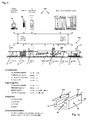
- the illustrated in Figure 1 extrusion plant consists of a control area 100 with control and regulation device, process computer and memory. Another area is the production area 101, in which the plant consists of a cable duct 20 * continuously generating units, which are explained below. Between the producing area 101 and the controlling area 100 a multiplicity of regulating and control tasks as well as measured variables are provided. This representation is schematic in nature and is intended to illustrate the complexity of the control task.
- a feed point y for a granulate, an extruder drive a and an extruder b are provided at the head of the extruder.
- a tool c is provided at the head of the extruder, which gives the cable channel 20 its profile and its shape.
- a portion of such a cable channel 20 *, as a strand, is provided between the head and the first inlet of the cooling section e.
- the cooling section e is interrupted by a measuring device d, which, for example, the thickness of the wall thickness of the extruded, in cross-section at least part-box-shaped extrusion component 20 * (here shown as a cable channel) measures.
- Suitable wall thicknesses are walls which are each specifically named in FIG.
- the trigger f and a saw g are provided as an example of a separating device, which cuts the cable channel produced continuously in the strand into individual pieces.
- individual cable duct pieces are produced which are fed to the further finishing and / or packaging process in a tipping trough h. This further process is symbolized by x.
- the cable channel 20 has its predetermined length, while the extruded cable channel 20 * is produced endlessly in one piece.
- FIG. 1 lists some setting variables, some result variables and some disturbance variables. They are related to those areas of the machine in which they occur.
- the screw speed is located in the area of the extruder a, b.
- the tool temperature is measured in the area of the tool c. Here several tool temperatures can be detected, at different points of the tool.
- the cooling water temperature is found in one of the several sections of the cooling section e. Again, several locations may be provided for measuring the cooling water temperature.
- An immersion depth is measurable or adjustable in the same cooling area. It relates to the immersion of the extruded component in a cooling medium.
- the result variables given are melt viscosity, melt temperature, dimensional accuracy and surface quality.
- the viscosity is measured in the area b of the extruder.
- the melt temperature is measured in the same area of the extruder.
- the dimensional accuracy of the extrusion component is detected in the measuring device d and / or in the sections in which the extrusion component is formed, such that, for example Thickness measurements on the extruded endless component 20 *, may be present at the cut-to-length individual component 20 or at another point in the production process.
- the surface quality is optically detected by a sensor, not shown, and may also be provided at a desired location in the course of the entire process after leaving the tool.
- Disturbance variables are indicated symbolically as air temperature, air humidity, air pressure and draft, which can be present at any point in the process in the process environment.
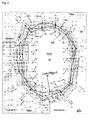
- the displayed scale arms can be differentiated according to the setting variables (left lower area), the result sizes (right lower area) and the disturbance variables (upper area).
- the setting variables include the scale arms 1, 2, 3, 4 and 14 to 16.
- the result variables include the scale arms 5 to 9.
- the disturbing variables include the scale arms 10 to 13.
- the scale arms may be directed inward or outward to greater or lesser values, depending on the physical size that they map.
- the scale arms are spaced apart, no scale arm falls on another scale arm. Each scale arm is independently visible. Some of the scale arms diverge, such as the scale arms 2, 3, 5, 6, 10 and 13. Some other scale arms are parallel, again other scale arms 11, 12 are perpendicular to the parallel scale arms.
- one of the polygons (red, or with a stronger line width) singled out, for example, at a speed of 5 1 / min has a characteristic on the speed scale arm and the result sizes a height value of about 55.8 mm has in the extrusion component.
- the focus polygon 50 has been recorded at an air pressure of between 1000mbar and 1010mbar and may either have been measured and stored from an earlier process state of the plant or represents the current system state (status) of the extrusion plant of FIG.
- the result quantities illustrated in FIG. 2 relate in part to the extrusion component according to FIG. 1a, for example the scale arms 7, 8 and 9 for deflection, height or width.
- the category of results also concerns the Viscosity and the melt temperature, as assigned to the production process under "result quantities" in Figure 1, and not the component.
- the immersion depth and the cooling water can be found on the scale arms 2, 3, which have been set for the area of the cooling section e by means of a presetting or there be measured.
- the categorization is completed.
- the forming of the upper and lower limits 39a, 39b is done by combining all the minimum values of each scale arm and connecting all the maximum values of each scale arm, here the sixteen shown scale arms, of which seven are assigned to the category of setting variables, five of the category of result sizes and four of the category of disturbances.
- the outermost polygon 39a and the innermost polygon 39b do not contain any real related characteristics and each do not themselves describe a machine state, but only map the lowest limit of all values (physical quantities) represented on scale arms, respectively top (physical) limit of all values represented on the scale arms.
- this representation is an example of the representation of a multiplicity of scale arms of the category result variables and of a plurality of scale arms of the category adjustment variables as well as a plurality of scale arms of the category disturbances.
- the exact numbering of the dimensions is within the scope of physical units that are quantitatively represented. Not shown, but readily understandable to Figure 2, are qualitative information, for example, the lump sum summarized physical process variables or physical component sizes.
- For the air humidity as a disturbance variable for example, can be given a flat rate: 'dry', 'standard' or 'wet', without specific indication of the humidity between 0% and 100%, as represented by scale arm 11.
- the upper and lower limits are not minimum and maximum, as in the case of quantitative data, but there is an inner and an outer value on one respective scale arm, which contributes to the formation of the continuous inner boundary 39b and the continuous outer boundary 39a.
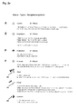
- FIG . 2 a illustrates four types of characteristic values that can be mapped into respective status polygons in FIG. 2. There are A-polygons, E-polygons, P-polygons and F-polygons.
- the A-polygons are a-priori knowledge of similar processes, products or machines. They may be incomplete and not all scale arms must have a corresponding point of this a priori polygon. If, for example, an additional measuring point for a temperature in a plant according to FIG. 1 is added, known and already stored statuses of the process plant can not serve this scale arm and it remains initially open. An associated characteristic does not exist in the memory 38a of the database.
- the P-polygons originating from production processes are recorded interactively manually, or can be stored automatically via an operating data acquisition (BDE).
- BDE operating data acquisition
- F-polygons are the F or forecast polygons that are interpolated, extrapolated, or similarly calculated using response surface methods. F-polygons may be updated automatically, depending on the progress of the information.
- each polygon and thus each associated group of characteristic values indicates a status of the system according to FIG. 1 and can fit into the horizon 39.
- the tools for changing the focus are Goal 48 and Delimiter 49 according to FIG. 2a.
- FIG. 12 corresponds to that of Figure 2 with regard to the scale arms and their arrangement, except that here machine statuses are located which lie within a highlighted corridor which is within the horizon 39 and does not extend beyond it. It is therefore necessary to set the currently running and producing plant according to FIG. 2 with the local focus polygon 50 in a new plant or production setting 50 * according to FIG. 12.
- the corresponding transition should be fast, reliable and goal-oriented. For this purpose, specifications are made, which are explained in the sequence of the next figures and which lead to desired points or desired results, which the new polygon 50 * completely or almost completely, but at least as a first approximation.
- the control of the production process can take place in many ways.
- New polygons 50 * can be set, can be preset, the system according to FIG. 1 can be monitored.
- the previous production process according to polygon 50 can be modified, which leads to the new process after 50 * according to FIG. 12. It can be optimized in this amendment.
- Sample preparations may be made and an analysis may be performed to analyze a production process represented by polygon 50 of FIG. 2 for usability.
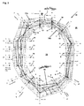
- the display representation according to FIG. 3 corresponds analogously to that of FIG. 2, only without identification of categories. Visible remains the contrasting horizon 39, its outer boundary 39a, its inner boundary 39b and the focus polygon 50, which corresponds to that of Figure 2.
- the scale arms 1 to 16 are identical and arranged identically.
- a display device 38 with a display as a screen, as a monitor or a machine screen is a.
- Figures 3 and 2 The illustration of Figures 3 and 2 is provided with respect to the edges of the horizon 39 with an inner and outer edge line 39a, 39b, but can also be omitted.
- the horizon appears to be contrastingly emphasized even without a rectilinear edge line for a plurality of inscribed polygons, all of which consist of the described four groups of polygons of Figure 2a, which are stored in the process memory 100 or 38a.
- a brightness distinction or a color distinction is then not necessary for the horizon.
- the visible boundary lines between each two adjacent scale arms would not be straightforward. Between each two adjacent scale arms, there are definitely kinks, caused by a cutting of different polygon sections of different machine status' (machine states).
- such kinks can be found at the edge between the axes 13, 12 or 10 and 11, through which there is a line intersecting with the focus polygon 50 of another of the remaining polygons 51 to 53. In other intermediate areas between two adjacent scale arms this also evident. In terms of purpose, both with the inner and outer rectilinear edge, as well as in the absence of this fixed edge, a contrasting highlighted horizon representation 39 is achieved.
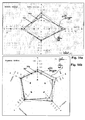
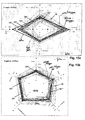
- the horizon 39 shown in FIGS. 2 and 3 is the primary horizon. Several secondary horizons can be derived from it, which will be explained with reference to FIGS. 4 to 6 .
- FIG. 3 The completeness of the surveyed experiential knowledge according to FIG. 3 is limited to one category in favor of a simpler overview and a shifting of the center of gravity in an optimization, attitude or other control.
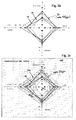
- a G horizon 32 of result quantities is formed, only taking into account the scale arms 5 to 9. This horizon 32 is likewise highlighted in contrast to an inner environment and an outer environment.
- the horizon 32 is also bounded as previously described for the primary horizon 39, only here by an outer edge line 32a and an inner edge line 32b.
- the focus polygon 50 is highlighted, in addition to the three remaining polygons 51, 52 and 53, but here only with characteristic values from the category of the result variables and the associated scale arms.
- the physical variables viscosity and melt temperature for the process and height, width and deflection for the product "extrusion component" are generally also replaceable with other physical result quantities.
- the associated scale arms are therefore numbered G5 to G9, to symbolize any physical quantities in the context of the product and the process.
- a goal orientation towards, for example, a higher speed at the scale arm 4 or an increase in the water temperature in the scale arm 3 can be more easily surveyed on the basis of the reduced horizon.
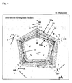
- FIGS. 5 and 6 explain the setpoint horizon as a further secondary horizon 31.
- a polygon can be selected out of the illustrated polygons around the focus polygon 50, which does not indicate a too low temperature in the cooling water and has a higher value at the rotational speed.
- a further compression of information can take place from several scale arms of the overview horizon of FIG.
- an averaged temperature value can be formed, which provides characteristic values for a scale arm 1 * not shown in FIG.
- the four temperature values of the scale arms 1 and 14 to 16 of Figure 2 are plotted in Figure 5 and the associated physical quantities are E17, E14, E15 and E16.
- These four temperature values are compressed by, for example, an averaging of several tool temperatures, which are then plotted as the mean value on the scale arm 1 * of FIG.
- This temperature and this scale arm are not shown in FIG. 2, but it allows working with condensed information and reduced horizons in the context of the secondary horizon 31.
- the secondary horizon 31 with outer boundary 31a and inner boundary 31b can also work without these straight edge lines, only by the existing abundance of the polygons 50 to 53 (also called line body).
- the corresponding embodiments are to be taken from the notes to Figure 3 and 2 and transferred here.
- disturbance variables can also have their own horizon, which is designed in accordance with the above secondary horizons, as the result variables and the adjustment variables form as secondary horizons 31, 32.
- Figures 3b and 3c show corresponding examples, taken from Figure 2 with secondary horizon 33 and four scale arms.
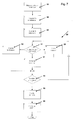
- FIG. 7 is an overview of a control method which functionally consists of individual steps, but which form part of an overall method. Therefore, when we speak of a "step 88", this merely describes a part of the overall process.
- step 88 The overview of the available empirical knowledge from the memory 38a of the controller 100 takes place in step 88. This corresponds to the figures 2 or 3.
- the restriction of the complexity ie the compression of information and the restriction to individual areas of a control process, take place in step 89.
- the above-described secondary horizons of FIGS. 3b, 3c, 4 or 6 stand for this.
- a restriction is also the reduction of several physical quantities, for example the temperatures according to FIG. 5, to an average which then finds representation in a newly formed scale arm of a secondary horizon.
- step 90 The overview can be improved in step 90, which is to be clarified with reference to FIGS. 6a, 4a.
- the secondary horizons are shown alone, which were illustrated with polygons with reference to Figures 4 and 6.
- the secondary horizon 31 for the adjustment variables and the secondary horizon 32 for the result variables are highlighted in contrast to the inner and outer environment.
- the outer edge and the inner edge are used.
- the representations according to FIGS. 6 a and 4 a are advantageously used when working with the delimiters 49 as an aid for influencing the process. These will be explained with reference to the following figures 8 ff.
- step 95 details may be displayed, which is at step 95, and the newly set process begins in step 96 with the adjustment of the new focus polygon 50 *.
- the tax procedure is for the change of the Actual state 50 to the desired state and new actual state 50 * of Figure 12 ended in this form.
- the tools described in FIG. 2a are to be used cumulatively, alternatively or in any combination, such as the focus polygon 50, the goal 48, the delimiter 49 and the determination of forecast polygons in 97, to which only later on will be received.
- the explanation should be continued here first with the delimiter.
- FIGS. 8a, 8b Two secondary horizons are shown in FIGS. 8a, 8b , that of the category of setting variables and that of the category of result variables. It is assumed that the query 91 of FIG. 7 was answered in such a way that a cluster is to be determined, which takes place in step 92. FIG. 8 a is thus located within step 92.
- a cluster defines a group of polygons that satisfy a given condition.
- the condition is specified manually, or it may have been specified numerically by a higher-level specification.
- the speed should be increased, and the water temperature may also be increased or should not fall too far.
- a delimiter 49 is placed, on the scale arm 4, which represents the speed.
- the used Delimiter is here a lower limit. He still leaves all polygons in the shortlist, which have characteristic values on the scale arm 4, which are above the selected minimum value of about 7 1 / min here. The remaining polygons are not shown in detail in Figure 8a, but define a corridor 31 'which lies within the outer edges.
- step 92 to another secondary horizon here the category of the result quantities of Figure 8b, also shows a corridor 32 'whose characteristics and polygons correspond to those selected by the delimiter 49 from the first secondary horizon of Figure 8a.
- FIGS. 8a and 8b are therefore related by the fact that each of a group of characteristic values belongs together, which together describe a (singular) machine status. Of these groups, several are selected by the delimiter 49, but not all that span the original first secondary horizon 31.
- a change between the secondary horizons provides an overview of the possibilities to achieve the desired selection or objective function 50 *. If the process or product gets into unwanted states (regions) in one or more of the result quantities, the placed delimiter 49 can no longer be maintained as intended.
- the second secondary horizon thus offers a possibility of checking the probability of realization of the chosen path.
- delimiters can be used to restrict the setpoint horizon to an even smaller corridor 31 ", as illustrated in FIGURE 9a
- the second delimiter 49a is placed at a minimum temperature of the cooling water in accordance with the chosen target direction
- values are below 16 ° C not desired, so that only a further limited number of polygons come into question, which satisfy both delimiters 49, 49a (greater than / equal to the lower limit values), and at the same time lie within the first secondary horizon 31.
- the setting of a goal is made, for example, with three default values in FIG. 10b in the second secondary horizon 32.
- the value for the deflection is specified as target 48. He should have the value 0 on the scale arm 7 (or at least come very close to him).
- the predetermined target values of width 92mm and height 56mm lead to a further reduced corridor 32 "', which is greatly reduced compared to the previous corridor 32". It can be assumed that there will be no polygon finding that fulfills all the default values identically, but the presentation and calculation method and the associated program work with a specification of goals so that the nearest polygons are selected. Here, settings are possible such that, for example, the distance from a selected goal is minimized, or an average of distances in multiple goals is used as the decision size, which polygons can be selected for set goals and used to form the reduced corridor.
- the last greatly reduced horizon 32 "' is formed under the influence of both the first and the second delimiters 49, 49a and at the same time under the influence of the three goals 48, 48a and 48b, as shown in each of Figures 10b and 10a are the scale arms 7, 8 and 9 as well as 3 and 4.
- control in the area of steps 91, 92 and 93 that is to say in section 99 of FIG. 7, can also be performed the other way round, ie the specification of delimiters 49 in the category of the result variables and the specification of goals 48 in the category of the setting variables.
- the individual steps 92 (determine cluster) and 93 (specify target) thereby correspond to a point specification and alternatively or cumulatively to an area specification by predetermining or selecting a remaining group of polygons. Such a range determination can be done below, above or on both sides by delimiter.
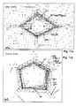
- a representation of remaining polygons shows the secondary horizons of Figures 11a and 11b.
- the new focus polygon which corresponds to the new state or the new setpoint and future actual value of the extrusion plant, has the desired high value at the speed, which is significantly above the predetermined minimum value by the delimiter 49, and has just at the cooling water temperature the minimum value set by the delimiter 49a.
- the goal achieved 50 * has virtually no deflection of the cable channel, represented on the scale arm 7, and is in height and width of the extruded cable channel very close to the Goal specifications.
- FIGS. 11a and 11b after being released by the "sufficient selection" in step 94, is step 95 in the sense of displaying details, but here still in the respective secondary horizon.
- the summary of the secondary horizons to a primary horizon reveals the two identified polygons as two continuous lines, which illustrates Figure 12.
- the reduced corridor 39 "'shown here in the context of the horizon 39 corresponds to the two strongly restricted secondary corridors 32'" and 31 "'.
- the expected deflection of the cable ducts defined in terms of height and width is slightly more than 0 mm, whereby this deflection on the scale arm 7 relates to the cut finished product after the separating device g of FIG. 1, in the course of further processing and packaging x.
- the setting can also be done by manually entering corresponding numerical values into these bright display / input fields.
- Pressing the function button 47a (Horizon) causes the areal display of horizon (s) or corridor (s). Pressing the function button 47b (Show All) displays all relevant polygons. Actuation of both function buttons 47a and 47b thus shows the polygons and the area representations. Pressing the function button 47d (Reset) removes all restrictions made so far; the values in the corresponding light and dark fields then agree again.
- Pressing or pressing is equivalent to "activating" the graphically symbolized button.
- the now extended set of process status polygons also includes those which extend beyond the "old” horizons 31 and 32 or corridors 31 '"and 32'", then it is possible to work according to "cluster" 92 or "goal” 93 be continued in the desired direction.
- the quality of the forecasted forecast status can also be evaluated in the ongoing production process.
- the output values of the setting variables of the process status 50 * are changed in small steps in the direction of the target specifications, as they correspond, for example, to the forecast status 53 *.
- the respective actual values of the result variables which are automatically acquired or interactively observed, are compared with their predicted setpoint values.
- this step-by-step approach such as a forecast status 52 *, results in large deviations between the process status calculated in advance and acquired experimentally or in the production process, for example, the polygon 52 * can serve as a starting point for new forecast calculations.
- a subset of the process statuses present in the process memory 38a is selected. This selection generally takes place successively at 99, with the aim of elaborating and analyzing currently valid process statuses, which take into account the specifications desired by the user with regard to the characteristic values of setting, result or disturbance variables, such as FIGS. 8a, 8b, 9a , 9b show.
- the "clustering" control method is accomplished by placing one or more graphical symbols 49 on one or more of the scale arms by means of a “mouse pointer”. This sets (in the mathematical sense) limits for the characteristic values on the respective scale arms. The consideration of these restrictions causes a selection of permissible process statuses, and the subset of the remaining line bodies selected thereby can then be highlighted as a contrasting corridor 31 ', 32', 31 ", 32", 39 "for better visual presentation. A more manageable subset then enables a simple balancing of alternative process statuses, thus enabling the user to possibly opt for a new, "better” process status and to make a corresponding change in the plant's production settings.
- the "clustering" control method 92 may also be done by keyboard input as well.
- keyboard input in the bright fields of the columns “upper” and “lower” limits of Figure 13 freely selectable characteristics for the desired Enter restriction of the respective physical size. The effects of these inputs can be tracked and interpreted directly in the updated graph. Conversely, the placement of a graphic delimiter symbol presented above also results in the updating of the corresponding table field content corresponding to FIG. 13.
- Goal control method 93 is indicated when the user has relatively precise wishful thinking (hence the term "goal") with respect to a characteristic or set of desired process status characteristics, but which should be approximately realistic (both individual values, as well as common group characteristics of a status).
- These "Goal" values will i.A. are located on portions of the scale arms within the decision horizons (see in particular Figure 10b), but they need not necessarily represent characteristics that are stored in the process memory.
- the user can now in turn also set Goals in two ways: on the one hand by placing one or more graphical symbols 48 by means of a "mouse pointer" on one or more of the scale arms (according to Figure 10b), on the other hand by entering the desired characteristic values as Specification of the respective physical size by means of the Tatstatur, as shown by way of example in the right column of Figure 13.
- the x results can be emphasized contrastingly in the decision horizons as line bodies, as illustrated in FIGS. 11a, 11b, 12, 14a and 14b; they can also be sorted and highlighted in the same way in the table 46 of FIG (not shown in 46 but easy to imagine).
- the "focus” polygon 50 in FIG. 2a or FIG. 3ff or 50 * in FIGS. 11a, 11b, 12, 13, 14a and 14b is used. Its selection, marking or graphical highlighting can in turn be done via keyboard input or graphic interaction. By entering or selecting the data record number (for example by means of a scroll function), a process status stored in the database 38a receives the focus. Alternatively, this can be done by marking a group of related, linearly connected characteristic values in one of the decision horizons by means of a "mouse pointer". The focus polygon is then displayed graphically highlighted in the decision horizons, at the same time its characteristics are identified in the table 46 of Figure 13 and shown in the focus column of Figure 13.
- the thus-defined focus polygon or the corresponding process status now serves as the center for a subsequent generation of "virtual" process status' in the vicinity thereof, with the aim of adding process memory 38a by additional, i.A. approximate process status'.
- the line bodies of these newly generated, as it were from the "nucleus" Focus polygon emergent 'process status' may be within the already known decision horizons, but they may well, at least in terms of some scale arms, beyond the previous limits - what the exploration of new, alternative process status' is of great interest.
- the polygons 51 *, 52 * and 53 * in FIGS. 15a, 15b illustrate this situation.
- buttons "Forecast” 47e in FIG. 13 start the calculation of the forecast polygons.
- known methods of mathematics in particular from the field of experimental design (Response Surface Methods), are used.
- the above-mentioned restrictions can optionally be additionally taken into account or ignored.
- the user can also select the number x 'of the desired forecast polygons here.
- a value for the step size or distance can be selected here, which also serves as a basis for the calculation of the forecast process status' and its "proximity" to one another in the sense of the similarity or distance measure already mentioned above.
- the x 'results can in turn be emphasized in the decision horizons as line bodies (FIGS. 15a, 15b); they can also be sorted and highlighted in their order in the table 46 of FIG. This is not shown in Figure 46, but it is easy to imagine.
Landscapes
- Engineering & Computer Science (AREA)
- Mechanical Engineering (AREA)
- Human Computer Interaction (AREA)
- Manufacturing & Machinery (AREA)
- Physics & Mathematics (AREA)
- General Physics & Mathematics (AREA)
- Automation & Control Theory (AREA)
- Management, Administration, Business Operations System, And Electronic Commerce (AREA)
- Extrusion Moulding Of Plastics Or The Like (AREA)
Applications Claiming Priority (1)
| Application Number | Priority Date | Filing Date | Title |
|---|---|---|---|
| DE102005020374A DE102005020374B4 (de) | 2005-05-02 | 2005-05-02 | Steuerung eines Produktionsprozesses für extrudierte Profilbauteile |
Publications (3)
| Publication Number | Publication Date |
|---|---|
| EP1719603A2 true EP1719603A2 (fr) | 2006-11-08 |
| EP1719603A3 EP1719603A3 (fr) | 2008-06-25 |
| EP1719603B1 EP1719603B1 (fr) | 2015-08-05 |
Family
ID=36711793
Family Applications (1)
| Application Number | Title | Priority Date | Filing Date |
|---|---|---|---|
| EP06113408.6A Expired - Lifetime EP1719603B1 (fr) | 2005-05-02 | 2006-05-02 | Commande d'un procédé de fabrication de profilés extrudés |
Country Status (2)
| Country | Link |
|---|---|
| EP (1) | EP1719603B1 (fr) |
| DE (1) | DE102005020374B4 (fr) |
Cited By (5)
| Publication number | Priority date | Publication date | Assignee | Title |
|---|---|---|---|---|
| WO2013182190A1 (fr) * | 2012-06-05 | 2013-12-12 | Hbf Fertigungssteuerungssysteme Dr. Bauer Kg | Procédé de fonctionnement sans défaillances d'une machine de fabrication |
| US20140074260A1 (en) * | 2012-09-12 | 2014-03-13 | Abb Technology Ag | Industrial plant equipment, process and maintenance optimization |
| EP3529036A1 (fr) * | 2016-10-19 | 2019-08-28 | Stadlhuber, Thomas | Procédé et dispositif pour produire des profilés en matière plastique |
| AT527020A1 (de) * | 2023-03-02 | 2024-09-15 | Engel Austria Gmbh | Verfahren zum Bedienen einer Formgebungsmaschine |
| CN119329035A (zh) * | 2024-12-20 | 2025-01-21 | 河北新欧汽车零部件科技有限公司 | 车用内夹条的共挤生产控制方法、设备及平台 |
Families Citing this family (2)
| Publication number | Priority date | Publication date | Assignee | Title |
|---|---|---|---|---|
| AT526314B1 (de) | 2022-07-11 | 2025-07-15 | Engel Austria Gmbh | Verfahren und vorrichtung zum visualisieren oder beurteilen eines prozesszustandes |
| EP4512590A1 (fr) | 2023-08-21 | 2025-02-26 | Siempelkamp Maschinen- und Anlagenbau GmbH | Procédé de préparation de valeurs pour des paramètres de processus d'un procédé de production d'un panneau de matériau de construction |
Family Cites Families (11)
| Publication number | Priority date | Publication date | Assignee | Title |
|---|---|---|---|---|
| US4675147A (en) * | 1983-04-06 | 1987-06-23 | Westinghouse Electic Corp. | Generating an integrated graphic display of the safety status of a complex process plant |
| DE3713400A1 (de) * | 1986-12-04 | 1988-06-09 | Mueanyagfel Dolgozo Vall | Verfahren und vorrichtung zum steuern von strangpressenreihen unter anwendung eines mikroprozessors |
| US5578256A (en) * | 1990-03-28 | 1996-11-26 | Moldflow Pty, Ltd | Control of injection moulding machine |
| DE4219259A1 (de) * | 1992-06-12 | 1993-12-16 | Karl Hehl | Verfahren zur Steuerung einer Kunststoff-Spritzgießmaschine |
| DE19503508A1 (de) * | 1995-02-03 | 1996-08-08 | Werner & Pfleiderer | Steuerungsverfahren für Extrudiermaschinen |
| GB0111215D0 (en) * | 2001-05-08 | 2001-06-27 | Curvaceous Software Ltd | Multi-variable process |
| DE10318204B4 (de) * | 2001-10-22 | 2012-09-06 | Fraunhofer-Gesellschaft zur Förderung der angewandten Forschung e.V. | Festlegen von Steuergrößen, Einstellungen oder technischen Parametern (Planungshilfe) |
| DE10151987C2 (de) * | 2001-10-22 | 2003-11-06 | Fraunhofer Ges Forschung | Vorbereiten der Auswahl von Steuergrößen für eine zeitlich und räumlich einzustellende Dosisverteilung eines Strahlengerätes |
| DE10230497A1 (de) * | 2002-07-06 | 2004-01-29 | Billion S.A. | Vorrichtung und Verfahren zum Betreiben einer Spritzgießmaschine |
| WO2004093971A2 (fr) * | 2003-04-22 | 2004-11-04 | Fraunhofer-Gesellschaft Zur Foerderung Der Angewandten Forschung E.V. | Determination de variables de reference, de valeurs de reglage ou de parametres techniques (aide a la planification) |
| US20040262799A1 (en) * | 2003-06-24 | 2004-12-30 | Jui-Hsiang Wang | Method of controlling an ejection molding process of an ejection molding machine |
-
2005
- 2005-05-02 DE DE102005020374A patent/DE102005020374B4/de not_active Expired - Fee Related
-
2006
- 2006-05-02 EP EP06113408.6A patent/EP1719603B1/fr not_active Expired - Lifetime
Cited By (6)
| Publication number | Priority date | Publication date | Assignee | Title |
|---|---|---|---|---|
| WO2013182190A1 (fr) * | 2012-06-05 | 2013-12-12 | Hbf Fertigungssteuerungssysteme Dr. Bauer Kg | Procédé de fonctionnement sans défaillances d'une machine de fabrication |
| US20140074260A1 (en) * | 2012-09-12 | 2014-03-13 | Abb Technology Ag | Industrial plant equipment, process and maintenance optimization |
| US9626634B2 (en) * | 2012-09-12 | 2017-04-18 | Abb Schweiz Ag | Industrial plant equipment, process and maintenance optimization |
| EP3529036A1 (fr) * | 2016-10-19 | 2019-08-28 | Stadlhuber, Thomas | Procédé et dispositif pour produire des profilés en matière plastique |
| AT527020A1 (de) * | 2023-03-02 | 2024-09-15 | Engel Austria Gmbh | Verfahren zum Bedienen einer Formgebungsmaschine |
| CN119329035A (zh) * | 2024-12-20 | 2025-01-21 | 河北新欧汽车零部件科技有限公司 | 车用内夹条的共挤生产控制方法、设备及平台 |
Also Published As
| Publication number | Publication date |
|---|---|
| EP1719603A3 (fr) | 2008-06-25 |
| DE102005020374B4 (de) | 2010-07-22 |
| EP1719603B1 (fr) | 2015-08-05 |
| DE102005020374A1 (de) | 2007-05-24 |
Similar Documents
| Publication | Publication Date | Title |
|---|---|---|
| DE10341764B4 (de) | Integrierte Modell-Vorhersagesteuerung und -Optimierung innerhalb eines Prozesssteuerungssystems | |
| DE69129440T2 (de) | Planungssystem für Herstellung | |
| DE102016010068B4 (de) | Numerische Steuerung mit Menü | |
| DE102010030691B4 (de) | Dialogsystem und Verfahren zur Untersuchung eines Bearbeitungsprozesses | |
| WO2018072773A2 (fr) | Procédé de surveillance d'un processus de production, procédé de déduction indirecte d'une dépendance systématique, procédé d'adaptation de la qualité, procédé de démarrage d'un processus de production, procédé de fabrication d'un produit d'extrusion et installation de fabrication d'un produit d'extrusion | |
| EP2561417B1 (fr) | Procédé pour introduire une configuration spatiale de dispositifs de fabrication dans un programme de planification assisté par ordinateur et son optimisation | |
| EP2824450B1 (fr) | Utilisation d'un procede d'evaluation d'un resultat d'une analyse thermique, produit de programme informatique et combinaison d'une installation de production ou de traitement et systeme pour la realisation de l'utilisation | |
| DE102020104952B4 (de) | Verwaltungsvorrichtung und verwaltungssystem | |
| DE102013011688A1 (de) | Datenanzeigevorrichtung für Maschinenwerkzeuge zur Anzeige von Daten aufgrund vorgegebener Zustände | |
| DE102020102406A1 (de) | Managementvorrichtung und managementsystem | |
| EP1623287B1 (fr) | Conception d'outils et de processus pour technique de formage | |
| DE102015206741A1 (de) | Bildung von Rüstfamilien für ein Bearbeitungssystem mit einer Werkzeugmaschine | |
| EP1719603B1 (fr) | Commande d'un procédé de fabrication de profilés extrudés | |
| DE102017009429A1 (de) | Informationsverarbeitungsvorrichtung | |
| EP4108411A2 (fr) | Procédé, système et produit de programme informatique permettant de surveiller un processus de formage | |
| DE69808582T2 (de) | Verfahren zur Dimensionierung eines auf einem Bildschirm angezeigten graphischen Objekts | |
| DE102016124285A1 (de) | Zustandsänderungsverwaltungssystem für eine fertigungszelle in einem zellensteuerungssystem | |
| WO2019233735A1 (fr) | Procédé de garantie de la qualité lors de la production d'un produit, dispositif de calcul et programme d'ordinateur | |
| DE102016123235A1 (de) | Betriebsverwaltungssystem zum direkten anzeigen eines arbeitsbefehls auf basis einer betriebsverwaltungsinformation an einer werkzeugmaschine | |
| AT522639B1 (de) | Vorrichtung und Verfahren zum Visualisieren oder Beurteilen eines Prozesszustandes | |
| EP4327171B1 (fr) | Procédé de commande de processus sur des machines de traitement de matières plastiques | |
| DE102005020352A1 (de) | Steuerung eines technischen Produktionsprozesses für technische Bauteile oder chemische Produkte/Erzeugnisse als technische Produkte | |
| DE60012636T2 (de) | Verfahren zur Steuerung eines Komplexen Dynamischen Prozesses | |
| DE102017003157A1 (de) | Numerische Steuerung | |
| DE4112036A1 (de) | Vorrichtung zur bearbeitungsschrittentscheidung in einer einrichtung zum erzeugen von nc-information |
Legal Events
| Date | Code | Title | Description |
|---|---|---|---|
| PUAI | Public reference made under article 153(3) epc to a published international application that has entered the european phase |
Free format text: ORIGINAL CODE: 0009012 |
|
| AK | Designated contracting states |
Kind code of ref document: A2 Designated state(s): AT BE BG CH CY CZ DE DK EE ES FI FR GB GR HU IE IS IT LI LT LU LV MC NL PL PT RO SE SI SK TR |
|
| AX | Request for extension of the european patent |
Extension state: AL BA HR MK YU |
|
| RAP1 | Party data changed (applicant data changed or rights of an application transferred) |
Owner name: TEHALIT GMBH Owner name: FRAUNHOFER-GESELLSCHAFT ZUR FOERDERUNG DER ANGEWAN |
|
| PUAL | Search report despatched |
Free format text: ORIGINAL CODE: 0009013 |
|
| AK | Designated contracting states |
Kind code of ref document: A3 Designated state(s): AT BE BG CH CY CZ DE DK EE ES FI FR GB GR HU IE IS IT LI LT LU LV MC NL PL PT RO SE SI SK TR |
|
| AX | Request for extension of the european patent |
Extension state: AL BA HR MK YU |
|
| RIC1 | Information provided on ipc code assigned before grant |
Ipc: G05B 19/409 20060101AFI20080520BHEP Ipc: B29C 47/92 20060101ALN20080520BHEP |
|
| 17P | Request for examination filed |
Effective date: 20081211 |
|
| 17Q | First examination report despatched |
Effective date: 20090120 |
|
| AKX | Designation fees paid |
Designated state(s): AT BE BG CH CY CZ DE DK EE ES FI FR GB GR HU IE IS IT LI LT LU LV MC NL PL PT RO SE SI SK TR |
|
| RAP1 | Party data changed (applicant data changed or rights of an application transferred) |
Owner name: FRAUNHOFER-GESELLSCHAFT ZUR FOERDERUNG DER ANGEWAN |
|
| GRAP | Despatch of communication of intention to grant a patent |
Free format text: ORIGINAL CODE: EPIDOSNIGR1 |
|
| INTG | Intention to grant announced |
Effective date: 20141125 |
|
| GRAS | Grant fee paid |
Free format text: ORIGINAL CODE: EPIDOSNIGR3 |
|
| GRAP | Despatch of communication of intention to grant a patent |
Free format text: ORIGINAL CODE: EPIDOSNIGR1 |
|
| INTG | Intention to grant announced |
Effective date: 20150601 |
|
| GRAA | (expected) grant |
Free format text: ORIGINAL CODE: 0009210 |
|
| AK | Designated contracting states |
Kind code of ref document: B1 Designated state(s): AT BE BG CH CY CZ DE DK EE ES FI FR GB GR HU IE IS IT LI LT LU LV MC NL PL PT RO SE SI SK TR |
|
| REG | Reference to a national code |
Ref country code: GB Ref legal event code: FG4D Free format text: NOT ENGLISH |
|
| REG | Reference to a national code |
Ref country code: CH Ref legal event code: EP |
|
| REG | Reference to a national code |
Ref country code: AT Ref legal event code: REF Ref document number: 741052 Country of ref document: AT Kind code of ref document: T Effective date: 20150815 |
|
| REG | Reference to a national code |
Ref country code: IE Ref legal event code: FG4D Free format text: LANGUAGE OF EP DOCUMENT: GERMAN |
|
| REG | Reference to a national code |
Ref country code: DE Ref legal event code: R096 Ref document number: 502006014455 Country of ref document: DE |
|
| REG | Reference to a national code |
Ref country code: LT Ref legal event code: MG4D |
|
| REG | Reference to a national code |
Ref country code: NL Ref legal event code: MP Effective date: 20150805 |
|
| PG25 | Lapsed in a contracting state [announced via postgrant information from national office to epo] |
Ref country code: LT Free format text: LAPSE BECAUSE OF FAILURE TO SUBMIT A TRANSLATION OF THE DESCRIPTION OR TO PAY THE FEE WITHIN THE PRESCRIBED TIME-LIMIT Effective date: 20150805 Ref country code: FI Free format text: LAPSE BECAUSE OF FAILURE TO SUBMIT A TRANSLATION OF THE DESCRIPTION OR TO PAY THE FEE WITHIN THE PRESCRIBED TIME-LIMIT Effective date: 20150805 Ref country code: GR Free format text: LAPSE BECAUSE OF FAILURE TO SUBMIT A TRANSLATION OF THE DESCRIPTION OR TO PAY THE FEE WITHIN THE PRESCRIBED TIME-LIMIT Effective date: 20151106 Ref country code: LV Free format text: LAPSE BECAUSE OF FAILURE TO SUBMIT A TRANSLATION OF THE DESCRIPTION OR TO PAY THE FEE WITHIN THE PRESCRIBED TIME-LIMIT Effective date: 20150805 |
|
| PG25 | Lapsed in a contracting state [announced via postgrant information from national office to epo] |
Ref country code: PT Free format text: LAPSE BECAUSE OF FAILURE TO SUBMIT A TRANSLATION OF THE DESCRIPTION OR TO PAY THE FEE WITHIN THE PRESCRIBED TIME-LIMIT Effective date: 20151207 Ref country code: SE Free format text: LAPSE BECAUSE OF FAILURE TO SUBMIT A TRANSLATION OF THE DESCRIPTION OR TO PAY THE FEE WITHIN THE PRESCRIBED TIME-LIMIT Effective date: 20150805 Ref country code: PL Free format text: LAPSE BECAUSE OF FAILURE TO SUBMIT A TRANSLATION OF THE DESCRIPTION OR TO PAY THE FEE WITHIN THE PRESCRIBED TIME-LIMIT Effective date: 20150805 Ref country code: IS Free format text: LAPSE BECAUSE OF FAILURE TO SUBMIT A TRANSLATION OF THE DESCRIPTION OR TO PAY THE FEE WITHIN THE PRESCRIBED TIME-LIMIT Effective date: 20151205 Ref country code: ES Free format text: LAPSE BECAUSE OF FAILURE TO SUBMIT A TRANSLATION OF THE DESCRIPTION OR TO PAY THE FEE WITHIN THE PRESCRIBED TIME-LIMIT Effective date: 20150805 |
|
| PG25 | Lapsed in a contracting state [announced via postgrant information from national office to epo] |
Ref country code: NL Free format text: LAPSE BECAUSE OF FAILURE TO SUBMIT A TRANSLATION OF THE DESCRIPTION OR TO PAY THE FEE WITHIN THE PRESCRIBED TIME-LIMIT Effective date: 20150805 |
|
| PG25 | Lapsed in a contracting state [announced via postgrant information from national office to epo] |
Ref country code: SK Free format text: LAPSE BECAUSE OF FAILURE TO SUBMIT A TRANSLATION OF THE DESCRIPTION OR TO PAY THE FEE WITHIN THE PRESCRIBED TIME-LIMIT Effective date: 20150805 Ref country code: EE Free format text: LAPSE BECAUSE OF FAILURE TO SUBMIT A TRANSLATION OF THE DESCRIPTION OR TO PAY THE FEE WITHIN THE PRESCRIBED TIME-LIMIT Effective date: 20150805 Ref country code: CZ Free format text: LAPSE BECAUSE OF FAILURE TO SUBMIT A TRANSLATION OF THE DESCRIPTION OR TO PAY THE FEE WITHIN THE PRESCRIBED TIME-LIMIT Effective date: 20150805 Ref country code: DK Free format text: LAPSE BECAUSE OF FAILURE TO SUBMIT A TRANSLATION OF THE DESCRIPTION OR TO PAY THE FEE WITHIN THE PRESCRIBED TIME-LIMIT Effective date: 20150805 Ref country code: IT Free format text: LAPSE BECAUSE OF FAILURE TO SUBMIT A TRANSLATION OF THE DESCRIPTION OR TO PAY THE FEE WITHIN THE PRESCRIBED TIME-LIMIT Effective date: 20150805 |
|
| REG | Reference to a national code |
Ref country code: DE Ref legal event code: R097 Ref document number: 502006014455 Country of ref document: DE |
|
| REG | Reference to a national code |
Ref country code: FR Ref legal event code: PLFP Year of fee payment: 11 |
|
| PG25 | Lapsed in a contracting state [announced via postgrant information from national office to epo] |
Ref country code: RO Free format text: LAPSE BECAUSE OF FAILURE TO SUBMIT A TRANSLATION OF THE DESCRIPTION OR TO PAY THE FEE WITHIN THE PRESCRIBED TIME-LIMIT Effective date: 20150805 |
|
| PLBE | No opposition filed within time limit |
Free format text: ORIGINAL CODE: 0009261 |
|
| STAA | Information on the status of an ep patent application or granted ep patent |
Free format text: STATUS: NO OPPOSITION FILED WITHIN TIME LIMIT |
|
| 26N | No opposition filed |
Effective date: 20160509 |
|
| PG25 | Lapsed in a contracting state [announced via postgrant information from national office to epo] |
Ref country code: SI Free format text: LAPSE BECAUSE OF FAILURE TO SUBMIT A TRANSLATION OF THE DESCRIPTION OR TO PAY THE FEE WITHIN THE PRESCRIBED TIME-LIMIT Effective date: 20150805 Ref country code: BE Free format text: LAPSE BECAUSE OF NON-PAYMENT OF DUE FEES Effective date: 20160531 |
|
| PG25 | Lapsed in a contracting state [announced via postgrant information from national office to epo] |
Ref country code: LU Free format text: LAPSE BECAUSE OF FAILURE TO SUBMIT A TRANSLATION OF THE DESCRIPTION OR TO PAY THE FEE WITHIN THE PRESCRIBED TIME-LIMIT Effective date: 20160502 |
|
| REG | Reference to a national code |
Ref country code: CH Ref legal event code: PL |
|
| PG25 | Lapsed in a contracting state [announced via postgrant information from national office to epo] |
Ref country code: CH Free format text: LAPSE BECAUSE OF NON-PAYMENT OF DUE FEES Effective date: 20160531 Ref country code: LI Free format text: LAPSE BECAUSE OF NON-PAYMENT OF DUE FEES Effective date: 20160531 |
|
| REG | Reference to a national code |
Ref country code: IE Ref legal event code: MM4A |
|
| REG | Reference to a national code |
Ref country code: FR Ref legal event code: PLFP Year of fee payment: 12 |
|
| PG25 | Lapsed in a contracting state [announced via postgrant information from national office to epo] |
Ref country code: IE Free format text: LAPSE BECAUSE OF NON-PAYMENT OF DUE FEES Effective date: 20160502 |
|
| REG | Reference to a national code |
Ref country code: AT Ref legal event code: MM01 Ref document number: 741052 Country of ref document: AT Kind code of ref document: T Effective date: 20160502 |
|
| PG25 | Lapsed in a contracting state [announced via postgrant information from national office to epo] |
Ref country code: AT Free format text: LAPSE BECAUSE OF NON-PAYMENT OF DUE FEES Effective date: 20160502 |
|
| REG | Reference to a national code |
Ref country code: FR Ref legal event code: PLFP Year of fee payment: 13 |
|
| PG25 | Lapsed in a contracting state [announced via postgrant information from national office to epo] |
Ref country code: HU Free format text: LAPSE BECAUSE OF FAILURE TO SUBMIT A TRANSLATION OF THE DESCRIPTION OR TO PAY THE FEE WITHIN THE PRESCRIBED TIME-LIMIT; INVALID AB INITIO Effective date: 20060502 Ref country code: CY Free format text: LAPSE BECAUSE OF FAILURE TO SUBMIT A TRANSLATION OF THE DESCRIPTION OR TO PAY THE FEE WITHIN THE PRESCRIBED TIME-LIMIT Effective date: 20150805 |
|
| PG25 | Lapsed in a contracting state [announced via postgrant information from national office to epo] |
Ref country code: TR Free format text: LAPSE BECAUSE OF FAILURE TO SUBMIT A TRANSLATION OF THE DESCRIPTION OR TO PAY THE FEE WITHIN THE PRESCRIBED TIME-LIMIT Effective date: 20150805 Ref country code: MC Free format text: LAPSE BECAUSE OF FAILURE TO SUBMIT A TRANSLATION OF THE DESCRIPTION OR TO PAY THE FEE WITHIN THE PRESCRIBED TIME-LIMIT Effective date: 20150805 |
|
| PG25 | Lapsed in a contracting state [announced via postgrant information from national office to epo] |
Ref country code: BG Free format text: LAPSE BECAUSE OF FAILURE TO SUBMIT A TRANSLATION OF THE DESCRIPTION OR TO PAY THE FEE WITHIN THE PRESCRIBED TIME-LIMIT Effective date: 20150805 |
|
| REG | Reference to a national code |
Ref country code: DE Ref legal event code: R082 Ref document number: 502006014455 Country of ref document: DE Representative=s name: LEONHARD, REIMUND, DIPL.-ING., DE |
|
| P01 | Opt-out of the competence of the unified patent court (upc) registered |
Effective date: 20230524 |
|
| PGFP | Annual fee paid to national office [announced via postgrant information from national office to epo] |
Ref country code: DE Payment date: 20250519 Year of fee payment: 20 |
|
| PGFP | Annual fee paid to national office [announced via postgrant information from national office to epo] |
Ref country code: GB Payment date: 20250522 Year of fee payment: 20 |
|
| PGFP | Annual fee paid to national office [announced via postgrant information from national office to epo] |
Ref country code: FR Payment date: 20250521 Year of fee payment: 20 |