EP1719624A2 - Passage de liquide formant un dispositif de guidage - Google Patents
Passage de liquide formant un dispositif de guidage Download PDFInfo
- Publication number
- EP1719624A2 EP1719624A2 EP06008872A EP06008872A EP1719624A2 EP 1719624 A2 EP1719624 A2 EP 1719624A2 EP 06008872 A EP06008872 A EP 06008872A EP 06008872 A EP06008872 A EP 06008872A EP 1719624 A2 EP1719624 A2 EP 1719624A2
- Authority
- EP
- European Patent Office
- Prior art keywords
- passage forming
- carriage
- guiding device
- forming member
- holding member
- Prior art date
- Legal status (The legal status is an assumption and is not a legal conclusion. Google has not performed a legal analysis and makes no representation as to the accuracy of the status listed.)
- Withdrawn
Links
- 239000007788 liquid Substances 0.000 title claims abstract description 29
- 238000005452 bending Methods 0.000 abstract description 20
- 238000003780 insertion Methods 0.000 description 17
- 230000037431 insertion Effects 0.000 description 17
- 238000011144 upstream manufacturing Methods 0.000 description 7
- 230000007246 mechanism Effects 0.000 description 4
- 238000004140 cleaning Methods 0.000 description 3
- 239000000463 material Substances 0.000 description 3
- 239000003086 colorant Substances 0.000 description 2
- 239000010808 liquid waste Substances 0.000 description 2
- 238000004519 manufacturing process Methods 0.000 description 2
- 238000000018 DNA microarray Methods 0.000 description 1
- 239000004698 Polyethylene Substances 0.000 description 1
- 239000007772 electrode material Substances 0.000 description 1
- 230000002349 favourable effect Effects 0.000 description 1
- 230000004048 modification Effects 0.000 description 1
- 238000012986 modification Methods 0.000 description 1
- 239000005416 organic matter Substances 0.000 description 1
- -1 polyethylene Polymers 0.000 description 1
- 229920000573 polyethylene Polymers 0.000 description 1
- 238000007789 sealing Methods 0.000 description 1
- 238000005549 size reduction Methods 0.000 description 1
Images
Classifications
-
- B—PERFORMING OPERATIONS; TRANSPORTING
- B41—PRINTING; LINING MACHINES; TYPEWRITERS; STAMPS
- B41J—TYPEWRITERS; SELECTIVE PRINTING MECHANISMS, i.e. MECHANISMS PRINTING OTHERWISE THAN FROM A FORME; CORRECTION OF TYPOGRAPHICAL ERRORS
- B41J2/00—Typewriters or selective printing mechanisms characterised by the printing or marking process for which they are designed
- B41J2/005—Typewriters or selective printing mechanisms characterised by the printing or marking process for which they are designed characterised by bringing liquid or particles selectively into contact with a printing material
- B41J2/01—Ink jet
- B41J2/17—Ink jet characterised by ink handling
- B41J2/175—Ink supply systems ; Circuit parts therefor
-
- B—PERFORMING OPERATIONS; TRANSPORTING
- B41—PRINTING; LINING MACHINES; TYPEWRITERS; STAMPS
- B41J—TYPEWRITERS; SELECTIVE PRINTING MECHANISMS, i.e. MECHANISMS PRINTING OTHERWISE THAN FROM A FORME; CORRECTION OF TYPOGRAPHICAL ERRORS
- B41J2/00—Typewriters or selective printing mechanisms characterised by the printing or marking process for which they are designed
- B41J2/005—Typewriters or selective printing mechanisms characterised by the printing or marking process for which they are designed characterised by bringing liquid or particles selectively into contact with a printing material
- B41J2/01—Ink jet
- B41J2/17—Ink jet characterised by ink handling
- B41J2/175—Ink supply systems ; Circuit parts therefor
- B41J2/17503—Ink cartridges
-
- B—PERFORMING OPERATIONS; TRANSPORTING
- B41—PRINTING; LINING MACHINES; TYPEWRITERS; STAMPS
- B41J—TYPEWRITERS; SELECTIVE PRINTING MECHANISMS, i.e. MECHANISMS PRINTING OTHERWISE THAN FROM A FORME; CORRECTION OF TYPOGRAPHICAL ERRORS
- B41J2/00—Typewriters or selective printing mechanisms characterised by the printing or marking process for which they are designed
- B41J2/005—Typewriters or selective printing mechanisms characterised by the printing or marking process for which they are designed characterised by bringing liquid or particles selectively into contact with a printing material
- B41J2/01—Ink jet
- B41J2/17—Ink jet characterised by ink handling
- B41J2/175—Ink supply systems ; Circuit parts therefor
- B41J2/17503—Ink cartridges
- B41J2/17533—Storage or packaging of ink cartridges
Definitions
- the present invention relates to a device for guiding a liquid passage forming member.
- Inkjet printers are widely known as liquid ejection apparatuses for ejecting liquid onto a target.
- a printer has a recording head mounted on a reciprocating carriage. Ink (liquid) is supplied to the recording head from ink cartridges (liquid containers). The recording head has nozzles, through which ink is ejected onto a recording medium, or a target, thereby subjecting the recording medium printing.
- Such printers include, for example, a printer disclosed in Japanese Laid-Open Patent Publication No. 2004-262092 , in which ink cartridges are mounted on a carriage (on-carriage type) and a printer disclosed in Japanese Laid-Open Patent Publication No. 2003-320680 , in which ink cartridges are not mounted on a carriage but fixed to a fixing position of the printer (off-carriage type).
- An ink cartridge of an on-carriage type printer has a small ink capacity due to a limited space on the carriage.
- ink cartridges need to be frequently replaced. Therefore, when performing a large amount of printing, not only replacement of ink cartridges needs to be performed manually, but also, the running costs are increased.
- some on-carriage type printers have been modified such that an external high capacity ink tank is connected to the ink cartridges on the carriage. When such a modification is applied, ink supply tubes (liquid passage forming members) for supplying ink from the external ink tank to the ink cartridges are routed inside the printer while being curved at several locations.
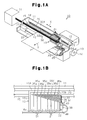
- ink cartridges are primarily attached to the carriage, and there is no need to route ink supply tubes. Therefore, partly due to demands for size reduction of printers, hardly any space exists between a frame 11 of a printer 10 and a rear surface 16d of a carriage 16 as shown in Fig. 1B. Even if ink supply tubes extending from an external ink tank are routed along a front surface 16a of the carriage 16, the tubes need to be curved toward an upper surface of the ink cartridges. A sufficient space for permitting the tubes to be curved cannot be easily created. Particularly, a recent increase in the types of ink colors has resulted in an increased number of ink supply tubes in a printer. This increases the size of a space for permitting the ink supply tubes to be curved.
- a guiding device guides, in a main body of a liquid ejection apparatus, a flexible passage forming member having a passage therein in a predetermined routing direction while curving the passage forming member.
- the guiding device includes a holding member. The holding member is engaged with a curved section of the passage forming member, and holds the curved section in an undeformable manner in the apparatus main body. The holding member guides the passage forming member in the routing direction.
- a guiding device that guides, in a main body of a liquid ejection apparatus, a plurality of flexible passage forming members each having a passage therein in a predetermined routing direction while curving the passage forming members.
- the liquid ejection apparatus includes a carriage that reciprocates in the apparatus main body.
- the carriage has a front surface parallel to the reciprocation direction, an upper surface parallel to the reciprocation direction, and a side surface perpendicular to the reciprocation direction.
- the guiding device fixes the passage forming members, which are arranged in parallel on the front surface along the reciprocation direction, to the side surface in a curved state on the side surface, and guides the passage forming members in parallel along the upper surface.
- a liquid ejection apparatus which is a printer 10
- a box-shaped apparatus main body which is a frame 11.
- a platen 12 is provided in a lower portion of the frame 11.
- the platen 12 extends along the longitudinal direction of the frame 11 (main scanning direction X shown in Fig. 1).
- the platen 12 is support supporting a target, which is a sheet of paper P.
- the platen 12 feeds the sheet of paper P along a sub-scanning direction Y perpendicular to the main scanning direction X.
- a front-rear direction, a left-right direction, and an up-down direction are defined with respect to the sub-scanning direction Y (direction in which the sheet of paper P is fed) defined as a frontward direction.
- a guide rod 15 extending along the platen 12 is provided above the platen 12.
- the guide rod 15 extends through and movably supports a carriage 16.
- a drive pulley 17 and a driven pulley 18 are rotatably supported in positions corresponding to both ends of the guide rod 15.
- the drive pulley 17 is connected to a carriage motor 19.
- a timing belt 20, to which the carriage 16 is fixed, is engaged with the drive pulley 17 and the driven pulley 18. Therefore, while being guided by the guide rod 15, the carriage 16 is moved along the main scanning direction X by the carriage motor 19 with the timing belt 20.
- the carriage 16 includes a first surface, which is a right side surface 16b intersecting the reciprocation direction (direction X) of the carriage 16, a second surface, which is an upper surface 16c extending along the reciprocation direction, and a third surface, which is a front surface 16a extending along the reciprocation direction.
- a recording head (not shown), which functions as a liquid ejection head, is mounted in a lower portion of the carriage 16. Nozzles (not shown) are provided in the lower surface of the recording head.
- Ink cartridges 21, which function as liquid containers, are detachably attached to the carriage 16 above the recording head. The number of the ink cartridges 21 is eight in this embodiment.
- the ink cartridges 21 are supplied with liquid, or ink (eight types of ink, which are dark and light types of magenta, cyan, yellow, and magenta) a high capacity ink tank 31 through a tube bundle 32 for supplying ink shown in Fig. 1A.
- a liquid waste tank 22 extending parallel to the platen 12 is located in the frame 11 below the platen 12.
- An absorbing member (not shown) that is made of, for example, porous pulp material, is accommodated in the liquid waste tank 22.
- a cleaning mechanism 23 is located in an end portion of the printer 10 (right end portion as viewed in Fig. 1A), or in a non-ejection area by which the sheet of paper P does not pass. The cleaning mechanism 23 draws ink remaining in the nozzles to prevent the nozzles from being clogged.
- the cleaning mechanism 23 has a cap 24 for sealing the recording head and a suction pump 25 functioning as a suction portion.
- the high capacity ink tank 31 functioning as a liquid retaining member, is located outside of the frame 11 of the printer 10 (on the left of the frame 11).
- the high capacity ink tank 31 accommodates eight high capacity ink packs (not shown) that retain ink of eight colors corresponding to the eight ink cartridges 21 on the carriage 16.
- the high capacity ink tank 31 is connected to the ink cartridges 21 with the tube bundle 32 functioning as a passage forming member.
- the tube bundle 32 is made of a flexible material such as polyethylene.
- the tube bundle 32 is drawn into the frame 11 through an insertion hole 33 formed in the frame 11.
- the tube bundle 32 is routed to the carriage 16 (the ink cartridges 21) by a tube guiding device 34, which function s as a passage forming member guiding device. That is, the upstream end of the tube bundle 32 is connected to the high capacity ink tank 31, while the downstream end of the tube bundle 32 is connected to the ink cartridges 21 on the carriage 16. Since the tube guiding device 34 for guiding the tube bundle 32 is a main feature of the present invention, the structure, as well as the manner in which the tube bundle 32 is routed in the frame 11, will be described below.
- Ink passages 35 (see Fig. 3), the number of which corresponds to the number of the ink packs in the high capacity ink tank 31, are defined in the tube bundle 32.
- the number of the ink passages 35 is eight. That is, the tube bundle 32 has tube members 35a, 35b, 35c, 35d, 35e, 35f, 35g, 35h, the number of which is eight in this embodiment.
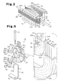
- Each of the tube members 35a, 35b, 35c, 35d, 35e, 35f, 35g, and 35h has a downstream end connected to the corresponding ink cartridge 21 as shown in Fig. 2.
- the tube members 35a-35h are formed as two integrated belts each having a predetermined number (four in this embodiment) of the tube members 35a-35h.
- the tube bundle 32 includes a first tube bundle 32A of four of the tube members, or the tube members 35a, 35b, 35c, 35d integrated to form a belt, and a second tube bundle 32B of the remaining four of the tube members, or the tube members 35e, 35f, 35g, 35h integrated to form a belt (see Fig. 3).
- each of the tube members 35a-35h communicates with the corresponding ink pack in the high capacity ink tank 31.
- the downstream end of each of the tube members 35a-35h is connected to the corresponding ink cartridge 21 on the carriage 16 as shown in Fig. 2. Therefore, ink in the high capacity ink tank 31 flows into the ink cartridges 21 through the ink passages 35 in the tube bundle 32, and is then supplied to the nozzles of the recording head (neither is shown) on the carriage 16.
- the tube guiding device 34 includes a first holding member 36, a second holding member 37, and an attachment member 38.
- the tube guiding device 34 is supported by and fixed to the carriage 16 with the attachment member 38, which integrates the first holding member 36 with the second holding member 37.
- the first holding member 36 holds a first curved section 32a of the first tube bundle 32A at a right side surface 16b of the carriage 16.
- the first tube bundle 32A extends from the high capacity ink tank 31 through the insertion hole 33 of the frame 11 and along the front surface 16a of the carriage 16.
- the first tube bundle 32A is routed from the front surface 16a to the right side surface 16b of the carriage 16, and then curved upward 90° from the front-rear direction on the right side surface 16b so that the first tube bundle 32A is directed toward the upper surface 16c of the carriage 16. Subsequently, the first tube bundle 32A is bent toward the upper surface 16c.
- a section of the first tube bundle 32A curved 90° on the right side surface 16b forms the first curved section 32a.
- the first holding member 36 holds the first curved section 32a in an undeformable manner relative to the carriage 16 (such that the curved state is maintained). In this manner, the first tube bundle 32A is routed by the first holding member 36.
- the first holding member 36 is formed as a hollow block, and includes a first inner edge surface 40 curved to form a quarter circle, and a first outer edge surface 41 curved at a radius of curvature greater than that of the first inner edge surface 40.
- an insertion passage 42 is formed to extend through the first holding member 36.
- the insertion passage 42 is curved to conform to the first inner edge surface 40 and the first outer edge surface 41.
- the cross-section of the insertion passage 42 is the same as the cross-sectional outline of the first tube bundle 32A.
- a vertical hole 44 is formed in and extends through a proximal end (the lower end as viewed in Fig. 3) 36a of the first holding member 36.
- the second holding member 37 When routing the second tube bundle 32B from the front surface 16a of the carriage 16 to the right side surface 16b, and then causing the second tube bundle 32B to extend from the right side surface 16b toward the upper surface 16c, the second holding member 37 holds a second curved section 32b in an undeformable manner in the frame 11 (that.is, such that the curved state is maintained).
- the second holding member 37 is formed as a hollow block, and includes a second inner edge surface 45 curved to form a quarter circle as viewed from a side, and a second outer edge surface 46 curved at a radius of curvature greater than that of the second inner edge surface 45.
- the entire second holding member 37 is shaped as a hollow block curved by a radius of curvature greater than that of the first holding member 36.
- the second inner edge surface 45 is shaped to conform to the first outer edge surface 41 of the first holding member 36.
- An insertion passage 47 is formed in the second holding member 37.
- the cross-sectional shape of the insertion passage 47 is the same the cross-sectional outline of the second tube bundle 32B.
- the insertion passage 47 is also formed to conform to the curvature of the second inner edge surface 45 and the second outer edge surface 46 of the second holding member 37.
- a vertical hole 49 is formed in and extends through a proximal end (the lower end as viewed in Fig. 3) 37a of the second holding member 37.
- the radius of curvature ⁇ 1 of the first outer edge surface 41 of the first holding member 36, which is located above the second holding member 37 as shown in Fig. 3 during assembly is less than the radius of curvature p2 of the second outer edge surface 46 of the second holding member 37.
- the first and second holding members 36, 37 hold the first and second curved sections 32a, 32b such that the radii of curvature of the tube members 35a to 35h (ink passages 35) are different from one another.
- the first holding member 36 holds the first curved section 32a such that the radii of curvature p3, p4 of the curved sections 35i, 35j of the tube members 35a, 35b satisfy the expression p3 ⁇ p4.
- the attachment member 38 is used for fixing the first holding member 36 and the second holding member 37 to the right side surface 16b of the carriage 16.
- the attachment member 38 is a substantially L-shaped thin plate, and includes a vertically extending attachment piece 51 and a support piece 52 extending in a horizontal direction from the lower end of the attachment piece 51.
- a threaded hole 53 is formed in the support piece 52.
- the first screw 43 is screwed to the threaded hole 53 to fix the first holding member 36 and the second holding member 37 to the attachment member 38.
- a threaded hole 54 is formed in the attachment piece 51.
- a second screw 48 is screwed to the threaded hole 54 to fix the attachment member 38 to the right side surface 16b of the carriage 16.
- the tube bundle 32 the upstream end of which is connected to the high capacity ink tank 31, has a downstream end inserted into the printer 10 through the insertion hole 33 of the frame 11.
- the tube bundle 32 is guided to extend in the moving direction (rightward as viewed in Fig. 1) of the carriage 16, or along the front surface 16a of the carriage 16 (parallel to the front surface 16a of the carriage 16).
- the downstream ends of the first tube bundle 32A and the second tube bundle 32B are inserted in to the insertion passages 42, 47 of the first and second holding members 36, 37. Then, as shown in Fig.
- the first tube bundle 32A and the second tube bundle 32B are curved so that the first and second curved sections 32a, 32b are engaged with the inner surfaces of the first and second insertion passage 42, 47.
- the first and second curved sections 32a, 32b are thus held to be undeformable.
- first holding member 36 and the second holding member 37 are stacked vertically such that the first outer edge surface 41 of the first holding member 36 contacts the second inner edge surface 45 of the second holding member 37, and the holes 44, 49 of the proximal ends 36a, 37a are aligned with the threaded hole 53 of the attachment member 38.
- first screw 43 is inserted into the holes 44, 49 and screwed to the threaded hole 53 of the attachment member 38. This integrally assembles the first holding member 36 and the second holding member 37 with the attachment member 38.
- the attachment piece 51 of the attachment member 38 is brought into contact with the right side surface 16b of the carriage 16, and the second screw 48 is screwed to the threaded hole 54 of the attachment piece 51.
- the downstream end of each of the tube members 35a to 35h is connected to the ink cartridge 21 of the corresponding color. Accordingly, the routing of the tube bundle 32 through the front surface 16a, the right side surface 16b, and the upper surface 16c of the carriage 16 in order is completed.
- a section of the tube bundle 32 that is upstream of the tube guiding device 34 (a section routed along the front surface 16a of the carriage 16) is flexed.
- a section of the tube bundle 32 that is downstream of the tube guiding device 34 that is, a section of the tube bundle 32 that is located on the upper surface of the carriage 16 is not flexed relative to the carriage 16.
- the orientation of a section of the tube bundle 32 that is downstream of the tube guiding device 34 that is, the orientation of a section of the tube bundle 32 that extends along the upper surface 16c of the carriage 16, is not flexed even if the carriage 16 reciprocates. Thus, unnecessary load is not applied to the joint between the downstream end of the tube bundle 32 and the ink cartridges 21. The connection between the tube bundle 32 and the ink cartridges 21 are stably maintained.
- the tube guiding device 34 may guide ink supply tubes for supplying ink from an ink tank located in the frame 11 to the ink cartridges 21.
- the tube bundle 32 may routed to extend along the rear surface 16d of the carriage 16.
- the tube bundle 32 of the above illustrated embodiment does not necessarily held on the right side surface 16b of the carriage 16, but may be held on the left side surface or the front surface of the carriage 16.
- the configuration in which the tube bundle 32 is held on the left side surface of the carriage 16 is favorable when the size of a space facing the front surface 16a of the carriage 16 is insufficient for allowing the tube bundle 32 to be flexed. That is, the space facing the left side surface of the carriage 16 can be used for permitting the tube bundle 32 to be flexed.
- the tube guiding device 34 may be supported in a position in the printer 10 other than the carriage 16.
- first holding member 36 and the second holding member 37 hold the first and second tube bundles 32 A, 32B may be changed as necessary.
- the first and second holding members 36, 37 may be each divided into two sections along the thickness.
- the first and second curved sections 32a, 32b are held between the divided sections, so that the first and second tube bundles 32A, 32B are supported.
- uneven sections that correspond to the first and second tube bundles 32A, 32B may be formed on the surfaces of the first and second holding members 36, 37 that face the right side surface 16b of the carriage 16.
- the first and second curved sections 32a, 32b are held between the uneven sections and the right side surface 16b of the carriage 16.
- a section of the tube bundle 32 that is upstream of the tube guiding device 34, that is, a section of the tube bundle 32 that extends along the front surface 16a of the carriage 16 may be formed as a tube bundle separate from a section of the tube bundle 32 that is downstream of the tube guiding device 34, that is, a section of the tube bundle 32 that extends along the upper surface 16c of the carriage 16.
- the lower end of the downstream section of the tube bundle 32 and the upper end of the downstream section of the tube bundle 32 are connected to the first and second holding members 36, 37.
- ink is stably supplied from the high capacity ink tank 31 to the ink cartridges 21 through the upstream section of the tube bundle 32, the first and second holding members 36, 37, and the downstream section of the tube bundle 32.
- the first holding member 36 and the second holding member 37 may be separately supported by the carriage 16.
- the present invention is applied to an on-carriage type inkjet printer, in which the ink cartridges 21 are mounted on the carriage 16.
- the present invention is not limited to this, but may be applied to an off-carriage type inkjet printer. That is, the tube guiding device 34 is suitable for routing the flexible tube bundle 32 in a limited space while efficiently bending the bundle 32 either in an on-carriage type inkjet printer or an off-carriage type inkjet printer.
- the present invention is applied to the printer 10, which ejects ink.
- the present invention may be applied to other types of liquid ejection apparatuses.
- the present invention may be applied to printing machines including fax machines and copy machines, a liquid ejection apparatus for ejecting liquid such as electrode material or color material used for manufacturing electroluminescent displays and surface light emitting displays.
- the present invention may also be applied to liquid ejecting apparatus for ejecting biological organic matter used for manufacturing biochips.
- the present invention may be applied to sample ejecting apparatus such as a precision pipette.
- the present invention may be applied to devices that use liquid other than ink.
Landscapes
- Ink Jet (AREA)
- Pens And Brushes (AREA)
Applications Claiming Priority (1)
| Application Number | Priority Date | Filing Date | Title |
|---|---|---|---|
| JP2005133445A JP2006305940A (ja) | 2005-04-28 | 2005-04-28 | 液体流路形成体誘導装置 |
Publications (2)
| Publication Number | Publication Date |
|---|---|
| EP1719624A2 true EP1719624A2 (fr) | 2006-11-08 |
| EP1719624A3 EP1719624A3 (fr) | 2008-04-09 |
Family
ID=36968790
Family Applications (1)
| Application Number | Title | Priority Date | Filing Date |
|---|---|---|---|
| EP06008872A Withdrawn EP1719624A3 (fr) | 2005-04-28 | 2006-04-28 | Passage de liquide formant un dispositif de guidage |
Country Status (6)
| Country | Link |
|---|---|
| US (1) | US7540587B2 (fr) |
| EP (1) | EP1719624A3 (fr) |
| JP (1) | JP2006305940A (fr) |
| KR (1) | KR100724827B1 (fr) |
| CN (1) | CN100503255C (fr) |
| TW (1) | TWI314104B (fr) |
Families Citing this family (10)
| Publication number | Priority date | Publication date | Assignee | Title |
|---|---|---|---|---|
| CN102896903B (zh) | 2008-03-25 | 2015-07-01 | 精工爱普生株式会社 | 液体供应流路装置以及使用该装置的液体喷射装置 |
| JP5223750B2 (ja) * | 2009-03-24 | 2013-06-26 | 株式会社リコー | 画像形成装置 |
| JP6024105B2 (ja) * | 2011-12-26 | 2016-11-09 | ブラザー工業株式会社 | インク供給装置 |
| EP2810779B1 (fr) * | 2012-01-30 | 2018-05-30 | Seiko Epson Corporation | Appareil d'enregistrement à jet d'encre |
| JP2013166302A (ja) * | 2012-02-15 | 2013-08-29 | Seiko Epson Corp | インクジェット記録装置 |
| TWI535574B (zh) * | 2012-02-28 | 2016-06-01 | Seiko Epson Corp | Ink jet recording device |
| WO2014024392A1 (fr) * | 2012-08-10 | 2014-02-13 | セイコーエプソン株式会社 | Dispositif d'éjection de liquide |
| JP6057058B2 (ja) * | 2012-08-10 | 2017-01-11 | セイコーエプソン株式会社 | 記録装置 |
| JP6379482B2 (ja) * | 2013-12-19 | 2018-08-29 | セイコーエプソン株式会社 | 液体噴射装置 |
| JP2017113917A (ja) * | 2015-12-22 | 2017-06-29 | セイコーエプソン株式会社 | 液体吐出装置 |
Citations (2)
| Publication number | Priority date | Publication date | Assignee | Title |
|---|---|---|---|---|
| JP2003320680A (ja) | 2002-02-28 | 2003-11-11 | Seiko Epson Corp | 液体噴射装置用液体供給チューブおよび液体噴射装置 |
| JP2004262092A (ja) | 2003-02-28 | 2004-09-24 | Seiko Epson Corp | 印刷装置及びその制御方法 |
Family Cites Families (9)
| Publication number | Priority date | Publication date | Assignee | Title |
|---|---|---|---|---|
| JPS60232964A (ja) * | 1984-05-04 | 1985-11-19 | Canon Inc | 液体噴射記録装置 |
| US6188417B1 (en) * | 1994-10-31 | 2001-02-13 | Hewlett-Packard Company | Fluidic adapter for use with an inkjet print cartridge having an internal pressure regulator |
| JPH11165447A (ja) | 1997-10-02 | 1999-06-22 | Canon Inc | インクジェットプリント装置 |
| DE10105352C1 (de) | 2001-02-05 | 2002-08-08 | Tally Computerdrucker Gmbh | Tintendrucker mit einer Absaugstation |
| US7744202B2 (en) | 2002-01-30 | 2010-06-29 | Hewlett-Packard Development Company, L.P. | Printing-fluid container |
| US6719414B2 (en) * | 2002-07-31 | 2004-04-13 | Hewlett-Packard Development Company, Lp | Ink tube carrier for a printer, and method |
| CN2573231Y (zh) | 2002-09-24 | 2003-09-17 | 缪则夫 | 喷墨打印机可持续供墨装置 |
| JP2004122633A (ja) * | 2002-10-03 | 2004-04-22 | Seiko Epson Corp | インクジェットプリンタのインク供給装置およびインクジェットプリンタ |
| JP2005035033A (ja) * | 2003-07-16 | 2005-02-10 | Seiko Epson Corp | インクジェット式記録装置及び液体噴射装置 |
-
2005
- 2005-04-28 JP JP2005133445A patent/JP2006305940A/ja not_active Withdrawn
-
2006
- 2006-04-26 US US11/411,746 patent/US7540587B2/en not_active Expired - Fee Related
- 2006-04-27 KR KR1020060038151A patent/KR100724827B1/ko not_active Expired - Fee Related
- 2006-04-28 EP EP06008872A patent/EP1719624A3/fr not_active Withdrawn
- 2006-04-28 CN CNB2006100790034A patent/CN100503255C/zh not_active Expired - Fee Related
- 2006-04-28 TW TW095115421A patent/TWI314104B/zh active
Patent Citations (2)
| Publication number | Priority date | Publication date | Assignee | Title |
|---|---|---|---|---|
| JP2003320680A (ja) | 2002-02-28 | 2003-11-11 | Seiko Epson Corp | 液体噴射装置用液体供給チューブおよび液体噴射装置 |
| JP2004262092A (ja) | 2003-02-28 | 2004-09-24 | Seiko Epson Corp | 印刷装置及びその制御方法 |
Also Published As
| Publication number | Publication date |
|---|---|
| US7540587B2 (en) | 2009-06-02 |
| US20060284945A1 (en) | 2006-12-21 |
| CN100503255C (zh) | 2009-06-24 |
| EP1719624A3 (fr) | 2008-04-09 |
| TW200702203A (en) | 2007-01-16 |
| KR100724827B1 (ko) | 2007-06-04 |
| TWI314104B (en) | 2009-09-01 |
| CN1853938A (zh) | 2006-11-01 |
| KR20060113508A (ko) | 2006-11-02 |
| JP2006305940A (ja) | 2006-11-09 |
Similar Documents
| Publication | Publication Date | Title |
|---|---|---|
| US9981478B2 (en) | Liquid ejecting device and head with flexible member for supplying liquid from a main tank | |
| EP1318019B1 (fr) | Imprimante à jet d'encre | |
| US8201932B2 (en) | Liquid supplying and collecting apparatus | |
| US8033656B2 (en) | Liquid feeding device and liquid ejecting apparatus | |
| US7540587B2 (en) | Liquid passage forming member guiding device | |
| JP4207217B2 (ja) | 印刷装置 | |
| JP5220137B2 (ja) | 液体噴射装置 | |
| JP4919731B2 (ja) | 画像形成装置 | |
| US6948802B2 (en) | Ink jet printer | |
| JP5942505B2 (ja) | 画像形成装置 | |
| HK1097808A (en) | Liquid passage forming member guiding device | |
| US7581811B2 (en) | Inkjet printer | |
| US7533975B2 (en) | Ink-jet recording apparatus | |
| JP6879452B2 (ja) | 液体噴射装置 | |
| JP6056880B2 (ja) | 液体噴射装置 | |
| JP5867378B2 (ja) | 液体噴射装置 | |
| US6742877B2 (en) | Ink-jet recording apparatus | |
| JP2015098177A (ja) | 液体噴射装置 | |
| JP5842604B2 (ja) | インク供給装置及び画像記録装置 | |
| US20250033365A1 (en) | Printing apparatus and tank | |
| JP2006095813A (ja) | 液体噴射装置および液体噴射装置の液体容器 | |
| JP2024012217A (ja) | インクジェットプリンタ | |
| JP2018103491A (ja) | 廃液タンク及び液体吐出装置 | |
| JP2024051186A (ja) | 記録装置 | |
| JP2006168242A (ja) | 液体噴射装置 |
Legal Events
| Date | Code | Title | Description |
|---|---|---|---|
| PUAI | Public reference made under article 153(3) epc to a published international application that has entered the european phase |
Free format text: ORIGINAL CODE: 0009012 |
|
| AK | Designated contracting states |
Kind code of ref document: A2 Designated state(s): AT BE BG CH CY CZ DE DK EE ES FI FR GB GR HU IE IS IT LI LT LU LV MC NL PL PT RO SE SI SK TR |
|
| AX | Request for extension of the european patent |
Extension state: AL BA HR MK YU |
|
| REG | Reference to a national code |
Ref country code: HK Ref legal event code: DE Ref document number: 1097808 Country of ref document: HK |
|
| PUAL | Search report despatched |
Free format text: ORIGINAL CODE: 0009013 |
|
| AK | Designated contracting states |
Kind code of ref document: A3 Designated state(s): AT BE BG CH CY CZ DE DK EE ES FI FR GB GR HU IE IS IT LI LT LU LV MC NL PL PT RO SE SI SK TR |
|
| AX | Request for extension of the european patent |
Extension state: AL BA HR MK YU |
|
| 17P | Request for examination filed |
Effective date: 20081008 |
|
| AKX | Designation fees paid |
Designated state(s): AT BE BG CH CY CZ DE DK EE ES FI FR GB GR HU IE IS IT LI LT LU LV MC NL PL PT RO SE SI SK TR |
|
| 17Q | First examination report despatched |
Effective date: 20090826 |
|
| STAA | Information on the status of an ep patent application or granted ep patent |
Free format text: STATUS: THE APPLICATION HAS BEEN WITHDRAWN |
|
| 18W | Application withdrawn |
Effective date: 20091113 |
|
| REG | Reference to a national code |
Ref country code: HK Ref legal event code: WD Ref document number: 1097808 Country of ref document: HK |