EP1719697B1 - Device for reducing motion of marine structure - Google Patents
Device for reducing motion of marine structure Download PDFInfo
- Publication number
- EP1719697B1 EP1719697B1 EP05719268.4A EP05719268A EP1719697B1 EP 1719697 B1 EP1719697 B1 EP 1719697B1 EP 05719268 A EP05719268 A EP 05719268A EP 1719697 B1 EP1719697 B1 EP 1719697B1
- Authority
- EP
- European Patent Office
- Prior art keywords
- marine structure
- overhang
- construction
- floating marine
- suppression device
- Prior art date
- Legal status (The legal status is an assumption and is not a legal conclusion. Google has not performed a legal analysis and makes no representation as to the accuracy of the status listed.)
- Expired - Lifetime
Links
- 230000033001 locomotion Effects 0.000 title claims description 138
- 239000013535 sea water Substances 0.000 claims description 76
- 230000001629 suppression Effects 0.000 claims description 70
- 238000004891 communication Methods 0.000 claims description 41
- 238000010276 construction Methods 0.000 description 92
- 230000000694 effects Effects 0.000 description 23
- JHJNPOSPVGRIAN-SFHVURJKSA-N n-[3-[(1s)-1-[[6-(3,4-dimethoxyphenyl)pyrazin-2-yl]amino]ethyl]phenyl]-5-methylpyridine-3-carboxamide Chemical compound C1=C(OC)C(OC)=CC=C1C1=CN=CC(N[C@@H](C)C=2C=C(NC(=O)C=3C=C(C)C=NC=3)C=CC=2)=N1 JHJNPOSPVGRIAN-SFHVURJKSA-N 0.000 description 6
- XLYOFNOQVPJJNP-UHFFFAOYSA-N water Substances O XLYOFNOQVPJJNP-UHFFFAOYSA-N 0.000 description 3
- 239000012530 fluid Substances 0.000 description 2
- 238000013016 damping Methods 0.000 description 1
- 238000002474 experimental method Methods 0.000 description 1
- 238000012986 modification Methods 0.000 description 1
- 230000004048 modification Effects 0.000 description 1
- 238000000545 stagnation point adsorption reflectometry Methods 0.000 description 1
- 238000012795 verification Methods 0.000 description 1
Images



Classifications
-
- B—PERFORMING OPERATIONS; TRANSPORTING
- B63—SHIPS OR OTHER WATERBORNE VESSELS; RELATED EQUIPMENT
- B63B—SHIPS OR OTHER WATERBORNE VESSELS; EQUIPMENT FOR SHIPPING
- B63B39/00—Equipment to decrease pitch, roll, or like unwanted vessel movements; Apparatus for indicating vessel attitude
-
- B—PERFORMING OPERATIONS; TRANSPORTING
- B63—SHIPS OR OTHER WATERBORNE VESSELS; RELATED EQUIPMENT
- B63B—SHIPS OR OTHER WATERBORNE VESSELS; EQUIPMENT FOR SHIPPING
- B63B35/00—Vessels or similar floating structures specially adapted for specific purposes and not otherwise provided for
- B63B35/44—Floating buildings, stores, drilling platforms, or workshops, e.g. carrying water-oil separating devices
-
- B—PERFORMING OPERATIONS; TRANSPORTING
- B63—SHIPS OR OTHER WATERBORNE VESSELS; RELATED EQUIPMENT
- B63B—SHIPS OR OTHER WATERBORNE VESSELS; EQUIPMENT FOR SHIPPING
- B63B39/00—Equipment to decrease pitch, roll, or like unwanted vessel movements; Apparatus for indicating vessel attitude
- B63B39/06—Equipment to decrease pitch, roll, or like unwanted vessel movements; Apparatus for indicating vessel attitude to decrease vessel movements by using foils acting on ambient water
- B63B2039/067—Equipment to decrease pitch, roll, or like unwanted vessel movements; Apparatus for indicating vessel attitude to decrease vessel movements by using foils acting on ambient water effecting motion dampening by means of fixed or movable resistance bodies, e.g. by bilge keels
Definitions
- the present invention relates to a marine structure of SPAR type, monocolumn type or other floating type marine structures, such as offshore oil platforms, floating type amusement facilities or hotels or the like comprising a motion suppression device.
- a floating type marine structure comprises a lower hull 12 of disk shape and a column 11 of cylindrical shape arranged on the lower hull 12.
- An inside water section 13 is formed within the column 11 so as to communicate with outside water via a water port 14 provided in the lower hull 12.
- a fin 18 is provided around an outer circumferential periphery of the lower hull 12 so as to spread obliquely downwardly.
- the fin 18 is fixedly supported to the lower hull 12 via a strut 19 with a gap being maintained between the fin 18 and outer circumferential periphery of the lower hull 12.
- JP 50 095989 A discloses a floating marine structure in the form of a ship comprising a motion suppression device in the form of an overhang structure that is provided at a position below the sea level to side walls of a keel structure so as to define a communication portion between the overhang structure and the respective side wall.
- the present invention is a marine structure comprising a motion suppression device as defined by claim 1.
- At least six lateral movement preventing plates are vertically provided in a space surrounded by the overhang structure, surrounding wall and floating marine structure.
- a seawater storing section is formed by the overhang structure, surrounding wall, floating marine structure and lateral movement preventing plates.
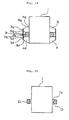
- Fig. 1 is a vertical cross sectional view showing a construction of a motion suppression device for marine structure of example 1 serving to explain features of the present invention.
- Fig. 2 is a bottom view of the embodiment 1 of Fig. 1 .
- Figs. 3 to 21 are vertical cross sectional views showing constructions of motion suppression devices for marine structures of examples and embodiments, respectively, of the present invention.
- a floating type marine structure comprises a floating marine structure 1 of cylindrical shape and an overhang structure 2 of ring shape fitted to a side wall of the floating marine structure 1 at a position below the sealevel and above a lower end of the side wall of the floating marine structure 1.
- the overhang structure 2 is arranged being fitted to an entire outer circumferential periphery of the floating marine structure 1.
- a surrounding wall 3a of ring shape is arranged so as to surround the entire circumferential periphery of the floating marine structure 1 but not to outwardly protrude beyond the outer circumferential periphery of the overhang structure 2.
- Communication openings 5a of slit shape are formed between the overhang structure 2 and surrounding wall 3a.
- a plurality of lateral movement preventing plates 4a are vertically provided in a space surrounded by the overhang structure 2, surrounding wall 3a and a side wall lower portion of the floating marine structure 1, a plurality of lateral movement preventing plates 4a are vertically provided.
- six lateral movement preventing plates 4a are radially arranged around the floating marine structure 1.
- Each of the lateral movement preventing plates 4a comprises an open end 6a that has its outer side connected to a lower end of the surrounding wall 3a and its inner side connected to the side wall lower end of the floating marine structure 1.
- seawater storing sections A in which seawater is stored are formed by a lower surface of the overhang structure 2, the surrounding wall 3a, the outer circumferential periphery of the floating marine structure 1 and the lateral movement preventing plates 4a, 4 a.
- the lateral movement preventing plates 4a are provided for the purpose that while the floating marine structure 1 unstably moves, the seawater in the seawater storing sections A is prevented from moving laterally (horizontally). While the number of the lateral movement preventing plates 4a to be provided differs according to the size of the floating marine structure 1, at least 6 pieces thereof are necessary to be provided, as shown in Fig. 2 .
- the seawater stored in the seawater storing sections A functions as a mass to suppress the motions of the floating marine structure 1.
- the size of the communication openings 5a is preferable to be such size that when the floating marine structure 1 resonantly moves, the seawater in the seawater storing sections A erupts so as to generate vortices.
- a surrounding wall 3b is arranged above the overhang structure 2.
- the surrounding wall 3b of ring shape is arranged above the outer circumferential periphery of the overhang structure 2 so as to surround the entire circumferential periphery of the floating marine structure 1 but not to outwardly protrude beyond the outer circumferential periphery of the overhang structure 2.
- Communication openings 5b of slit shape are formed between the overhang structure 2 and surrounding wall 3b.
- lateral movement preventing plates 4b are vertically provided, wherein the lateral movement preventing plates 4b are radially arranged around the floating marine structure 1 and the number thereof is at least 6 as in the case of Fig. 2 .
- seawater storing sections B are likewise formed.
- Each of the lateral movement preventing plates 4b comprises an open end 6b that has its outer side connected to an upper end of the surrounding wall 3b and its inner side connected to the side wall upper portion of the floating marine structure 1.
- a surrounding wall 3c is arranged to spread obliquely downwardly below the overhang structure 2.
- the surrounding wall 3c of truncated cone shape is arranged below the outer circumferential periphery of the overhang structure 2 so as to surround the entire circumferential periphery of the floating marine structure 1.
- Communication openings 5c of slit shape are formed between the overhang structure 2 and surrounding wall 3c.
- lateral movement preventing plates 4c are vertically provided, wherein the lateral movement preventing plates 4c are radially arranged around the floating marine structure 1 and the number thereof is at least 6 as in the case of Fig. 2 .
- seawater storing sections A are formed.
- Each of the lateral movement preventing plates 4c comprises an open end 6c that has its outer side connected to a lower end of the surrounding wall 3c and its inner side connected to the side wall lower end of the floating marine structure 1.
- a surrounding wall 3d is arranged below a space on the outer side of the outer circumferential periphery of the overhang structure 2.
- the surrounding wall 3d of ring shape is arranged below the space on the outer side of the outer circumferential periphery of the overhang structure 2 so as to surround the entire circumferential periphery of the floating marine structure 1.
- Communication openings 5d of slit shape are formed between the overhang structure 2 and surrounding wall 3d.
- lateral movement preventing plates 4d are vertically provided, wherein the lateral movement preventing plates 4d are radially arranged around the floating marine structure 1 and the number thereof is at least 6 as in the case of Fig. 2 .
- seawater storing sections A are formed.
- Each of the lateral movement preventing plates 4d comprises an open end 6d that has its outer side connected to a lower end of the surrounding wall 3d and its inner side connected to the side wall lower end of the floating marine structure 1.
- a surrounding wall 3e is arranged to spread obliquely downwardly.
- the surrounding wall 3e of truncated cone shape is arranged below the space on the outer side of the outer circumferential periphery of the overhang structure 2 so as to surround the entire circumferential periphery of the floating marine structure 1.
- Communication openings 5e of slit shape are formed between the overhang structure 2 and surrounding wall 3e.
- lateral movement preventing plates 4e are vertically provided, wherein the lateral movement preventing plates 4e are radially arranged around the floating marine structure 1 and the number thereof is at least 6 as in the case of Fig. 2 .
- seawater storing sections A are formed.
- Each of the lateral movement preventing plates 4e comprises an open end 6e that has its outer side connected to a lower end of the surrounding wall 3e and its inner side connected to the side wall lower end of the floating marine structure 1.
- the example 2 and example 3 are combined. That is, the surrounding wall 3b, etc. above the overhang structure 2, as shown in Fig. 3 , and the surrounding wall 3c, etc. below the overhang structure 2, as shown in Fig. 4 , are arranged.
- a surrounding wall 3f of inverse truncated cone shape is arranged to spread obliquely upwardly above the overhang structure 2.
- the surrounding wall 3c of truncated cone shape, etc. are arranged below the overhang structure 2.
- the surrounding wall 3f of inverse truncated cone shape is arranged above the overhang structure 2 so as to surround the entire circumferential periphery of the floating marine structure 1.
- Communication openings 5f of slit shape are formed between the overhang structure 2 and surrounding wall 3f.
- lateral movement preventing plates 4f are vertically provided, wherein the lateral movement preventing plates 4f are radially arranged around the floating marine structure 1 and the number thereof is at least 6 as in the case of Fig. 2 .
- seawater storing sections B are formed.
- Each of the lateral movement preventing plates 4f comprises an open end 6f that has its outer side connected to an upper end of the surrounding wall 3f and its inner side connected to the side wall upper portion of the floating marine structure 1.
- the example 2 ( Fig. 3 ) and example 4 ( Fig. 5 ) are combined. That is, the surrounding wall 3b, etc. above the overhang structure 2, as shown in Fig. 3 , and the surrounding wall 3d, etc. below the overhang structure 2, as shown in Fig. 5 , are arranged.
- the example 2 ( Fig. 3 ) and example 5 ( Fig. 6 ) are combined. That is, the surrounding wall 3b, etc. above the overhang structure 2, as shown in Fig. 3 , and the surrounding wall 3e, etc. below the overhang structure 2, as shown in Fig. 6 , are arranged.
- the construction below the overhang structure 2 of the example 8 ( Fig. 9 ) is replaced with the construction below the overhang structure 2 of the example 5 ( Fig. 6 ). That is, the surrounding wall 3f, etc. above the overhang structure 2, as in the case of Fig. 9 , and the surrounding wall 3e, etc. below the overhang structure 2, as in the case of Fig. 6 , are arranged.
- a surrounding wall 3g is arranged above the space on the outer side of the outer circumferential periphery of the overhang structure 2.
- the surrounding wall 3d, etc. are arranged below the overhang structure 2.
- the surrounding wall 3g of ring shape of the same size as the surrounding wall 3d is arranged above the overhang structure 2 so as to surround the entire circumferential periphery of the floating marine structure 1.
- Communication openings 5g of slit shape are formed between the overhang structure 2 and surrounding wall 3g.
- lateral movement preventing plates 4g are vertically provided, wherein the lateral movement preventing plates 4g are radially arranged around the floating marine structure 1 and the number thereof is at least 6 as in the case of Fig. 2 .
- seawater storing sections B are formed.
- Each of the lateral movement preventing plates 4g comprises an open end 6g that has its outer side connected to an upper end of the surrounding wall 3g and its inner side connected to the side wall upper portion of the floating marine structure 1.
- the surrounding wall 3d, etc. below the overhang structure 2 of the example 12 are replaced with the surrounding wall 3e, etc. below the overhang structure 2 of the example 5 ( Fig. 6 ).
- a surrounding wall 3h of inverse truncated cone shape is arranged to spread obliquely upwardly.
- the surrounding wall 3e of truncated cone shape, etc. are arranged below the overhang structure 2.
- the surrounding wall 3h of inverse truncated cone shape is arranged above the space on the outer side of the outer circumferential periphery of the overhang structure 2 so as to surround the entire circumferential periphery of the floating marine structure 1.
- Communication openings 5h of slit shape are formed between the overhang structure 2 and surrounding wall 3h.
- lateral movement preventing plates 4h are vertically provided, wherein the lateral movement preventing plates 4h are radially arranged around the floating marine structure 1 and the number thereof is at least 6 as in the case of Fig. 2 .
- seawater storing sections B are formed.
- Each of the lateral movement preventing plates 4h comprises an open end 6h that has its outer side connected to an upper end of the surrounding wall 3h and its inner side connected to the side wall upper portion of the floating marine structure 1.
- an overhang structure 2a of ring shape is arranged with a gap between the overhang structure 2a and side wall of the floating marine structure 1 at a position below the sealevel and above the lower end of the side wall of the floating marine structure 1.
- a communication portion 7 is formed between the overhang structure 2a and side wall of the floating marine structure 1.
- the lateral movement preventing plates 4a, 4b, 4c and 4f are likewise arranged so that the seawater storing sections A and/or B are formed.
- a communication portion wall 9 is provided surrounding the space on the outer side of the outer circumferential periphery of the overhang structure 2 so that the surrounding walls 3d and 3g are connected to each other via the communication portion wall 9.
- the surrounding wall 3d of ring shape and the lateral movement preventing plates 4d are arranged so as to surround the entire outer circumferential periphery of the floating marine structure 1 and thereby the seawater storing sections A are formed. Also, above the overhang structure 2, the surrounding wall 3g of ring shape of the same size as the surrounding wall 3d and the lateral movement preventing plates 4g are arranged so as to surround the entire outer circumferential periphery of the floating marine structure 1 and thereby the seawater storing sections B are formed.
- the communication portion wall 9 connecting to the surrounding walls 3d and 3g, respectively, is arranged on the outer side of the outer circumferential periphery of the overhang structure 2.
- a communication portion 7a of ring shape communicating with the seawater storing sections A and B, respectively, is formed between an inner side of the communication portion wall 9 and the outer circumferential periphery of the overhang structure 2.
- seawater stored in the seawater storing sections A and B passes through the communication portion 7a to flow into the seawater storing sections B and A, respectively.
- the effect to suppress the motions of the floating marine structure 1 can be further enhanced.
- a communication portion wall 9 is provided surrounding the space on the outer side of the outer circumferential periphery of the overhang structure 2 so that the surrounding walls 3e and 3h are connected to each other via the communication portion wall 9.
- the surrounding wall 3e of ring shape and the lateral movement preventing plates 4e are arranged so as to surround the entire outer circumferential periphery of the floating marine structure 1 and thereby the seawater storing sections A are formed. Also, above the overhang structure 2, the surrounding wall 3h of ring shape of the same size as the surrounding wall 3e and the lateral movement preventing plates 4h are arranged so as to surround the entire outer circumferential periphery of the floating marine structure 1 and thereby the seawater storing sections B are formed.
- the communication portion wall 9 connecting to the surrounding walls 3e and 3h, respectively, is arranged on the outer side of the outer circumferential periphery of the overhang structure 2.
- a communication portion 7a of ring shape communicating with the seawater storing sections A and B, respectively, is formed between an inner side of the communication portion wall 9 and the outer circumferential periphery of the overhang structure 2.
- seawater stored in the seawater storing sections A and B passes through the communication portion 7a to flow into the seawater storing sections B and A, respectively.
- the effect to suppress the motions of the floating marine structure 1 can be further enhanced.
- an overhang structure 2b has a central portion of its outer circumferential periphery protruded outwardly.
- the surrounding wall 3d of ring shape and the lateral movement preventing plates 4d are arranged so as to surround the entire outer circumferential periphery of the floating marine structure 1 and thereby the seawater storing sections A are formed.
- the surrounding wall 3g of ring shape of the same size as the surrounding wall 3d and the lateral movement preventing plates 4g are arranged so as to surround the entire outer circumferential periphery of the floating marine structure 1 and thereby the seawater storing sections B are formed.
- the communication portion wall 9 connecting to the surrounding walls 3d and 3g, respectively, is arranged on the outer side of the outer circumferential periphery of the overhang structure 2b.
- a communication portion 7b of ring shape communicating with the seawater storing sections A and B, respectively, is formed between the inner side of the communication portion wall 9 and the outwardly protruded outer circumferential periphery of the overhang structure 2b.
- an orifice portion 10 is formed by an inner side surface of the communication portion wall 9 and a protruded end portion of the outer circumferential periphery of the overhang structure 2b.
- seawater stored in the seawater storing sections A and B passes through the communication portion 7b to flow into the seawater storing sections B and A, respectively.
- the seawater flows through the orifice portion 10 flow velocity of the seawater is increased and the damping effect becomes large. Hence, the effect to suppress the motions of the floating marine structure 1 can be further enhanced.
- orifice portion 10 is also applicable to the construction of the embodiment 2 shown in Fig. 18 .
- construction of the orifice portion is not limited thereto but may be such that an upper end or lower end of the outer circumferential periphery of the overhang structure 2b protrudes outwardly or the communication portion wall 9 protrudes inwardly toward the overhang structure 2b.
- an overhang structure 2c has a central portion of its inner side surface protruded inwardly toward the floating marine structure 1.
- the overhang structure 2c of ring shape is arranged with a gap between the overhang structure 2c and side wall of the floating marine structure 1 at a position below the sealevel and above the lower end of the side wall of the floating marine structure 1.
- a communication portion 7c is formed between the overhang structure 2c and side wall of the floating marine structure 1.
- the overhang structure 2c has the vertical directional central portion of its inner side surface protruded inwardly.
- an orifice portion 10 is formed by the side wall of the floating marine structure 1 and a protruded end portion of the inner side surface of the overhang structure 2c.
- the lateral movement preventing plates 4a, 4b, 4c and 4f are likewise arranged so that the seawater storing sections A and/or B are formed.
- an overhang structure 2d has its inner side surface arranged obliquely relative to the side wall of the floating marine structure 1.
- the overhang structure 2d of ring shape is arranged with a gap between the overhang structure 2d and side wall of the floating marine structure 1 at a position below the sealevel and above the lower end of the side wall of the floating marine structure 1.
- a communication portion 7d is formed between the overhang structure 2d and side wall of the floating marine structure 1.
- the overhang structure 2d has an upper end portion of its oblique inner side surface protruded inwardly.
- an orifice portion 10 is formed by the side wall of the floating marine structure 1 and a protruded end portion of the inner side surface of the overhang structure 2d.
- the lateral movement preventing plates 4a, 4b, 4c and 4f are likewise arranged so that the seawater storing sections A and/or B are formed.
- Figs. 1 to 21 illustrate only the portions below the sealevel of the construction of the floating marine structure 1 and the construction on or above the sealevel may be freely set independent thereof.
- a plurality of the floating marine structures 1 as shown in Figs. 1 to 21 are provided and a common station is placed thereon so as to be positioned above the sealevel, it can be appropriately used as amusement facilities or hotels.
- the horizontal cross sectional shapes of the floating marine structure 1, overhang structures 2, 2a, surrounding walls 3a, 3b, 3c, 3d, 3e, 3f, 3g and 3h and communication portion wall 9 are not limited to the circular shape but may be other various shapes including a polygon, octagon, square or the like.
- overhang structures 2, 2a, 2b, 2c and 2d are not limited to those having the square or substantially square vertical cross sectional shapes as shown in Figs. 1 to 21 but may be a structure of thin plate shape including a disk or the like.
- the surrounding walls 3a, 3c, 3d and 3e below the overhang structures 2, 2a are arranged so as not to downwardly protrude beyond the lower end of the floating marine structure 1, they are not limited thereto but may be of such a shape as to downwardly protrude beyond the lower end of the floating marine structure 1.
- the open ends 6a, 6c, 6d and 6e of the lateral movement preventing plates 4a, 4c, 4d and 4e are arranged to have their outer side connected to the lower ends of the surrounding walls 3a, 3c, 3d and 3e and their inner side connected to the side wall lower end of the floating marine structure 1.
Landscapes
- Engineering & Computer Science (AREA)
- Chemical & Material Sciences (AREA)
- Combustion & Propulsion (AREA)
- Mechanical Engineering (AREA)
- Ocean & Marine Engineering (AREA)
- Architecture (AREA)
- Civil Engineering (AREA)
- Structural Engineering (AREA)
- Revetment (AREA)
- Bridges Or Land Bridges (AREA)
- Exhaust Silencers (AREA)
Applications Claiming Priority (2)
| Application Number | Priority Date | Filing Date | Title |
|---|---|---|---|
| JP2004047519 | 2004-02-24 | ||
| PCT/JP2005/002549 WO2005080189A1 (ja) | 2004-02-24 | 2005-02-18 | 海洋構造物の動揺低減装置 |
Publications (3)
| Publication Number | Publication Date |
|---|---|
| EP1719697A1 EP1719697A1 (en) | 2006-11-08 |
| EP1719697A4 EP1719697A4 (en) | 2012-11-28 |
| EP1719697B1 true EP1719697B1 (en) | 2014-05-21 |
Family
ID=34879477
Family Applications (1)
| Application Number | Title | Priority Date | Filing Date |
|---|---|---|---|
| EP05719268.4A Expired - Lifetime EP1719697B1 (en) | 2004-02-24 | 2005-02-18 | Device for reducing motion of marine structure |
Country Status (7)
| Country | Link |
|---|---|
| EP (1) | EP1719697B1 (ja) |
| JP (1) | JP4388548B2 (ja) |
| CN (1) | CN100526153C (ja) |
| ES (1) | ES2489520T3 (ja) |
| NO (1) | NO337078B1 (ja) |
| PT (1) | PT1719697E (ja) |
| WO (1) | WO2005080189A1 (ja) |
Families Citing this family (14)
| Publication number | Priority date | Publication date | Assignee | Title |
|---|---|---|---|---|
| JP4781954B2 (ja) * | 2006-09-22 | 2011-09-28 | 三菱重工業株式会社 | 浮体構造物 |
| CN101918270A (zh) * | 2008-02-27 | 2010-12-15 | 三菱重工业株式会社 | 浮体结构物 |
| US20100260554A1 (en) * | 2009-04-09 | 2010-10-14 | Yun Ding | Heave plate on floating offshore structure |
| KR101129633B1 (ko) * | 2009-04-29 | 2012-03-28 | 삼성중공업 주식회사 | 부유식 해양 구조물 |
| EP2480610B1 (en) | 2009-09-24 | 2017-11-29 | Basf Se | Migration-free coloured copolycondensates for colouring polymers |
| FR2970696B1 (fr) * | 2011-01-25 | 2013-02-08 | Ideol | Corps flottant annulaire |
| CN102490876B (zh) * | 2011-12-23 | 2014-04-02 | 新疆金风科技股份有限公司 | 浮动式海上风机运动抑制装置及用于海上风机的浮动基础 |
| FR3005698B1 (fr) * | 2013-05-17 | 2015-04-24 | IFP Energies Nouvelles | Eolienne offshore sur support flottant comportant une combinaison de moyens d'amortissement |
| JP6366124B2 (ja) * | 2013-06-26 | 2018-08-01 | ジャパンマリンユナイテッド株式会社 | 浮体構造物 |
| CN105480392B (zh) * | 2016-01-15 | 2017-05-31 | 江苏海事职业技术学院 | 一种抗冲击、防倾覆、波浪能转换的船舶附加装置 |
| CN105836062B (zh) * | 2016-04-01 | 2017-11-10 | 上海理工大学 | 单柱式平台风电装置 |
| FR3054522B1 (fr) | 2016-07-26 | 2019-04-05 | IFP Energies Nouvelles | Support flottant comportant un flotteur et une plaque d'amortissement avec section variable avec la profondeur |
| CN110803263A (zh) * | 2018-08-06 | 2020-02-18 | 吴植融 | 一种直筒式浮式平台的减动结构 |
| JP7076344B2 (ja) * | 2018-09-10 | 2022-05-27 | 日立造船株式会社 | 係留システム |
Family Cites Families (9)
| Publication number | Priority date | Publication date | Assignee | Title |
|---|---|---|---|---|
| US3708985A (en) * | 1970-12-07 | 1973-01-09 | Texaco Inc | Articulated marine platform |
| JPS5095989A (ja) * | 1973-12-25 | 1975-07-30 | ||
| JPS62292587A (ja) * | 1986-06-10 | 1987-12-19 | Sumitomo Heavy Ind Ltd | 半潜水式海洋構造物の潜水浮力体 |
| JP2772109B2 (ja) * | 1989-06-15 | 1998-07-02 | 三菱重工業株式会社 | 浮遊式海洋構造物 |
| JPH0656074A (ja) | 1992-08-10 | 1994-03-01 | Mitsubishi Heavy Ind Ltd | 浮遊式海洋構造物 |
| CN1043132C (zh) * | 1993-07-26 | 1999-04-28 | 麦克德莫特国际公司 | 用于近海甲板安装的能量吸收装置 |
| US5875728A (en) * | 1994-03-28 | 1999-03-02 | Shell Oil Company | Spar platform |
| NO310550B1 (no) * | 1997-12-12 | 2001-07-23 | Navion As | Stabiliseringsanordning for flytende produksjons-, lagrings- og lossefartöy |
| KR100556075B1 (ko) * | 2000-11-13 | 2006-03-07 | 싱글 뷰이 무어링스 인크. | 횡단 스커트를 포함하는 선박 |
-
2005
- 2005-02-18 JP JP2006510236A patent/JP4388548B2/ja not_active Expired - Fee Related
- 2005-02-18 WO PCT/JP2005/002549 patent/WO2005080189A1/ja not_active Ceased
- 2005-02-18 CN CN 200580005696 patent/CN100526153C/zh not_active Expired - Fee Related
- 2005-02-18 ES ES05719268.4T patent/ES2489520T3/es not_active Expired - Lifetime
- 2005-02-18 EP EP05719268.4A patent/EP1719697B1/en not_active Expired - Lifetime
- 2005-02-18 PT PT05719268T patent/PT1719697E/pt unknown
-
2006
- 2006-09-22 NO NO20064302A patent/NO337078B1/no not_active IP Right Cessation
Also Published As
| Publication number | Publication date |
|---|---|
| EP1719697A1 (en) | 2006-11-08 |
| PT1719697E (pt) | 2014-08-25 |
| ES2489520T3 (es) | 2014-09-02 |
| WO2005080189A1 (ja) | 2005-09-01 |
| JPWO2005080189A1 (ja) | 2007-10-25 |
| NO20064302L (no) | 2006-09-22 |
| JP4388548B2 (ja) | 2009-12-24 |
| CN1922072A (zh) | 2007-02-28 |
| NO337078B1 (no) | 2016-01-18 |
| EP1719697A4 (en) | 2012-11-28 |
| CN100526153C (zh) | 2009-08-12 |
Similar Documents
| Publication | Publication Date | Title |
|---|---|---|
| EP1719697B1 (en) | Device for reducing motion of marine structure | |
| EP2684792B1 (en) | Spar type floating structure | |
| KR101119854B1 (ko) | 탄화수소의 시추 또는 생산을 위한 해양 플랫폼 | |
| US7900570B2 (en) | Roll motion damping device for a floating body | |
| AU2019317324B2 (en) | Damping structure of straight cylinder type floating platform | |
| US20170313390A1 (en) | Semi-submersible with triangular columns | |
| WO2009107208A1 (ja) | 浮体構造物 | |
| KR101860115B1 (ko) | 돌출부재를 가진 부유식 해양 구조물용 플랫폼 및 이를 포함하는 반잠수식 해양 구조물 | |
| JP2019521906A (ja) | フロートと開口列を有する減衰板とを有する浮体式支持構造体 | |
| JP4781954B2 (ja) | 浮体構造物 | |
| KR100852375B1 (ko) | 해양구조물용 동요저감장치 | |
| JP5758501B2 (ja) | 浮体式風力発電装置 | |
| JPH0635910Y2 (ja) | 船尾防振ダンパー | |
| KR20180002918A (ko) | 문풀 저항 감소장치 | |
| JP2007126060A (ja) | 可撓性ブイ | |
| JPH10244989A (ja) | 低動揺型浮体構造物 | |
| KR200474803Y1 (ko) | 횡동요 감쇠 탱크 | |
| JPH0810553Y2 (ja) | 抵抗減少型船尾防振ダンパー | |
| JP2007008288A (ja) | 高波浪用ブイ | |
| JP6347556B2 (ja) | 建造物の制振装置 | |
| JP2024011377A (ja) | 動揺抑制部材および水上構造物の施工方法 | |
| AU2016371151A1 (en) | Pontoon-type semi-submersible platform | |
| KR20240116291A (ko) | 해수분출공을 가지는 해상구조물의 부유식 충돌보호 장치 및 이를 이용한 해상구조물의 충돌보호 방법 | |
| JP2007253753A (ja) | 杭式係留装置 | |
| JP2017109780A (ja) | 溢水防止装置及び貯蔵用タンク |
Legal Events
| Date | Code | Title | Description |
|---|---|---|---|
| PUAI | Public reference made under article 153(3) epc to a published international application that has entered the european phase |
Free format text: ORIGINAL CODE: 0009012 |
|
| 17P | Request for examination filed |
Effective date: 20060825 |
|
| AK | Designated contracting states |
Kind code of ref document: A1 Designated state(s): AT BE BG CH CY CZ DE DK EE ES FI FR GB GR HU IE IS IT LI LT LU MC NL PL PT RO SE SI SK TR |
|
| DAX | Request for extension of the european patent (deleted) | ||
| A4 | Supplementary search report drawn up and despatched |
Effective date: 20121026 |
|
| RIC1 | Information provided on ipc code assigned before grant |
Ipc: B63B 35/44 20060101AFI20121022BHEP Ipc: B63B 39/03 20060101ALI20121022BHEP |
|
| 17Q | First examination report despatched |
Effective date: 20130129 |
|
| GRAP | Despatch of communication of intention to grant a patent |
Free format text: ORIGINAL CODE: EPIDOSNIGR1 |
|
| INTG | Intention to grant announced |
Effective date: 20131219 |
|
| RIN1 | Information on inventor provided before grant (corrected) |
Inventor name: MATSUURA, MASAMI NAGASAKI RES. & DEV. CTR. Inventor name: NISHIGAKI, MAKOTO NAGASAKI RES. & DEV. CTR. |
|
| GRAS | Grant fee paid |
Free format text: ORIGINAL CODE: EPIDOSNIGR3 |
|
| GRAA | (expected) grant |
Free format text: ORIGINAL CODE: 0009210 |
|
| AK | Designated contracting states |
Kind code of ref document: B1 Designated state(s): AT BE BG CH CY CZ DE DK EE ES FI FR GB GR HU IE IS IT LI LT LU MC NL PL PT RO SE SI SK TR |
|
| REG | Reference to a national code |
Ref country code: GB Ref legal event code: FG4D |
|
| REG | Reference to a national code |
Ref country code: CH Ref legal event code: EP |
|
| REG | Reference to a national code |
Ref country code: AT Ref legal event code: REF Ref document number: 669451 Country of ref document: AT Kind code of ref document: T Effective date: 20140615 |
|
| REG | Reference to a national code |
Ref country code: IE Ref legal event code: FG4D |
|
| REG | Reference to a national code |
Ref country code: DE Ref legal event code: R096 Ref document number: 602005043706 Country of ref document: DE Effective date: 20140703 |
|
| REG | Reference to a national code |
Ref country code: PT Ref legal event code: SC4A Free format text: AVAILABILITY OF NATIONAL TRANSLATION Effective date: 20140806 |
|
| REG | Reference to a national code |
Ref country code: ES Ref legal event code: FG2A Ref document number: 2489520 Country of ref document: ES Kind code of ref document: T3 Effective date: 20140902 |
|
| REG | Reference to a national code |
Ref country code: NL Ref legal event code: T3 |
|
| REG | Reference to a national code |
Ref country code: AT Ref legal event code: MK05 Ref document number: 669451 Country of ref document: AT Kind code of ref document: T Effective date: 20140521 |
|
| REG | Reference to a national code |
Ref country code: LT Ref legal event code: MG4D |
|
| PG25 | Lapsed in a contracting state [announced via postgrant information from national office to epo] |
Ref country code: FI Free format text: LAPSE BECAUSE OF FAILURE TO SUBMIT A TRANSLATION OF THE DESCRIPTION OR TO PAY THE FEE WITHIN THE PRESCRIBED TIME-LIMIT Effective date: 20140521 Ref country code: LT Free format text: LAPSE BECAUSE OF FAILURE TO SUBMIT A TRANSLATION OF THE DESCRIPTION OR TO PAY THE FEE WITHIN THE PRESCRIBED TIME-LIMIT Effective date: 20140521 Ref country code: IS Free format text: LAPSE BECAUSE OF FAILURE TO SUBMIT A TRANSLATION OF THE DESCRIPTION OR TO PAY THE FEE WITHIN THE PRESCRIBED TIME-LIMIT Effective date: 20140921 Ref country code: GR Free format text: LAPSE BECAUSE OF FAILURE TO SUBMIT A TRANSLATION OF THE DESCRIPTION OR TO PAY THE FEE WITHIN THE PRESCRIBED TIME-LIMIT Effective date: 20140822 |
|
| PG25 | Lapsed in a contracting state [announced via postgrant information from national office to epo] |
Ref country code: SE Free format text: LAPSE BECAUSE OF FAILURE TO SUBMIT A TRANSLATION OF THE DESCRIPTION OR TO PAY THE FEE WITHIN THE PRESCRIBED TIME-LIMIT Effective date: 20140521 Ref country code: PL Free format text: LAPSE BECAUSE OF FAILURE TO SUBMIT A TRANSLATION OF THE DESCRIPTION OR TO PAY THE FEE WITHIN THE PRESCRIBED TIME-LIMIT Effective date: 20140521 Ref country code: AT Free format text: LAPSE BECAUSE OF FAILURE TO SUBMIT A TRANSLATION OF THE DESCRIPTION OR TO PAY THE FEE WITHIN THE PRESCRIBED TIME-LIMIT Effective date: 20140521 |
|
| PG25 | Lapsed in a contracting state [announced via postgrant information from national office to epo] |
Ref country code: EE Free format text: LAPSE BECAUSE OF FAILURE TO SUBMIT A TRANSLATION OF THE DESCRIPTION OR TO PAY THE FEE WITHIN THE PRESCRIBED TIME-LIMIT Effective date: 20140521 Ref country code: DK Free format text: LAPSE BECAUSE OF FAILURE TO SUBMIT A TRANSLATION OF THE DESCRIPTION OR TO PAY THE FEE WITHIN THE PRESCRIBED TIME-LIMIT Effective date: 20140521 Ref country code: RO Free format text: LAPSE BECAUSE OF FAILURE TO SUBMIT A TRANSLATION OF THE DESCRIPTION OR TO PAY THE FEE WITHIN THE PRESCRIBED TIME-LIMIT Effective date: 20140521 Ref country code: SK Free format text: LAPSE BECAUSE OF FAILURE TO SUBMIT A TRANSLATION OF THE DESCRIPTION OR TO PAY THE FEE WITHIN THE PRESCRIBED TIME-LIMIT Effective date: 20140521 Ref country code: BE Free format text: LAPSE BECAUSE OF FAILURE TO SUBMIT A TRANSLATION OF THE DESCRIPTION OR TO PAY THE FEE WITHIN THE PRESCRIBED TIME-LIMIT Effective date: 20140521 Ref country code: CZ Free format text: LAPSE BECAUSE OF FAILURE TO SUBMIT A TRANSLATION OF THE DESCRIPTION OR TO PAY THE FEE WITHIN THE PRESCRIBED TIME-LIMIT Effective date: 20140521 |
|
| REG | Reference to a national code |
Ref country code: DE Ref legal event code: R097 Ref document number: 602005043706 Country of ref document: DE |
|
| PLBE | No opposition filed within time limit |
Free format text: ORIGINAL CODE: 0009261 |
|
| STAA | Information on the status of an ep patent application or granted ep patent |
Free format text: STATUS: NO OPPOSITION FILED WITHIN TIME LIMIT |
|
| 26N | No opposition filed |
Effective date: 20150224 |
|
| REG | Reference to a national code |
Ref country code: DE Ref legal event code: R097 Ref document number: 602005043706 Country of ref document: DE Effective date: 20150224 |
|
| PG25 | Lapsed in a contracting state [announced via postgrant information from national office to epo] |
Ref country code: SI Free format text: LAPSE BECAUSE OF FAILURE TO SUBMIT A TRANSLATION OF THE DESCRIPTION OR TO PAY THE FEE WITHIN THE PRESCRIBED TIME-LIMIT Effective date: 20140521 |
|
| PG25 | Lapsed in a contracting state [announced via postgrant information from national office to epo] |
Ref country code: LU Free format text: LAPSE BECAUSE OF FAILURE TO SUBMIT A TRANSLATION OF THE DESCRIPTION OR TO PAY THE FEE WITHIN THE PRESCRIBED TIME-LIMIT Effective date: 20150218 |
|
| REG | Reference to a national code |
Ref country code: CH Ref legal event code: PL |
|
| PG25 | Lapsed in a contracting state [announced via postgrant information from national office to epo] |
Ref country code: LI Free format text: LAPSE BECAUSE OF NON-PAYMENT OF DUE FEES Effective date: 20150228 Ref country code: MC Free format text: LAPSE BECAUSE OF FAILURE TO SUBMIT A TRANSLATION OF THE DESCRIPTION OR TO PAY THE FEE WITHIN THE PRESCRIBED TIME-LIMIT Effective date: 20140521 Ref country code: CH Free format text: LAPSE BECAUSE OF NON-PAYMENT OF DUE FEES Effective date: 20150228 |
|
| REG | Reference to a national code |
Ref country code: IE Ref legal event code: MM4A |
|
| REG | Reference to a national code |
Ref country code: FR Ref legal event code: PLFP Year of fee payment: 12 |
|
| PG25 | Lapsed in a contracting state [announced via postgrant information from national office to epo] |
Ref country code: IE Free format text: LAPSE BECAUSE OF NON-PAYMENT OF DUE FEES Effective date: 20150218 |
|
| REG | Reference to a national code |
Ref country code: FR Ref legal event code: PLFP Year of fee payment: 13 |
|
| PG25 | Lapsed in a contracting state [announced via postgrant information from national office to epo] |
Ref country code: BG Free format text: LAPSE BECAUSE OF FAILURE TO SUBMIT A TRANSLATION OF THE DESCRIPTION OR TO PAY THE FEE WITHIN THE PRESCRIBED TIME-LIMIT Effective date: 20140521 Ref country code: HU Free format text: LAPSE BECAUSE OF FAILURE TO SUBMIT A TRANSLATION OF THE DESCRIPTION OR TO PAY THE FEE WITHIN THE PRESCRIBED TIME-LIMIT; INVALID AB INITIO Effective date: 20050218 |
|
| PG25 | Lapsed in a contracting state [announced via postgrant information from national office to epo] |
Ref country code: CY Free format text: LAPSE BECAUSE OF FAILURE TO SUBMIT A TRANSLATION OF THE DESCRIPTION OR TO PAY THE FEE WITHIN THE PRESCRIBED TIME-LIMIT Effective date: 20140521 |
|
| PG25 | Lapsed in a contracting state [announced via postgrant information from national office to epo] |
Ref country code: TR Free format text: LAPSE BECAUSE OF FAILURE TO SUBMIT A TRANSLATION OF THE DESCRIPTION OR TO PAY THE FEE WITHIN THE PRESCRIBED TIME-LIMIT Effective date: 20140521 |
|
| REG | Reference to a national code |
Ref country code: FR Ref legal event code: PLFP Year of fee payment: 14 |
|
| REG | Reference to a national code |
Ref country code: DE Ref legal event code: R082 Ref document number: 602005043706 Country of ref document: DE Representative=s name: HENKEL & PARTNER MBB PATENTANWALTSKANZLEI, REC, DE Ref country code: DE Ref legal event code: R082 Ref document number: 602005043706 Country of ref document: DE Representative=s name: PATENTANWAELTE HENKEL, BREUER & PARTNER MBB, DE Ref country code: DE Ref legal event code: R081 Ref document number: 602005043706 Country of ref document: DE Owner name: MITSUBISHI SHIPBUILDING CO., LTD., YOKOHAMA-SH, JP Free format text: FORMER OWNER: MITSUBISHI HEAVY INDUSTRIES, LTD., TOKYO, JP |
|
| REG | Reference to a national code |
Ref country code: GB Ref legal event code: 732E Free format text: REGISTERED BETWEEN 20180809 AND 20180815 |
|
| REG | Reference to a national code |
Ref country code: ES Ref legal event code: PC2A Owner name: MITSUBISHI SHIPBUILDING CO., LTD. Effective date: 20181003 |
|
| REG | Reference to a national code |
Ref country code: NL Ref legal event code: PD Owner name: MITSUBISHI SHIPBUILDING CO., LTD.; JP Free format text: DETAILS ASSIGNMENT: CHANGE OF OWNER(S), ASSIGNMENT; FORMER OWNER NAME: MITSUBISHI HEAVY INDUSTRIES, LTD. Effective date: 20180903 |
|
| PGFP | Annual fee paid to national office [announced via postgrant information from national office to epo] |
Ref country code: DE Payment date: 20200204 Year of fee payment: 16 Ref country code: IT Payment date: 20200128 Year of fee payment: 16 Ref country code: PT Payment date: 20200217 Year of fee payment: 16 Ref country code: GB Payment date: 20200206 Year of fee payment: 16 Ref country code: NL Payment date: 20200130 Year of fee payment: 16 Ref country code: ES Payment date: 20200302 Year of fee payment: 16 |
|
| PGFP | Annual fee paid to national office [announced via postgrant information from national office to epo] |
Ref country code: FR Payment date: 20200113 Year of fee payment: 16 |
|
| REG | Reference to a national code |
Ref country code: DE Ref legal event code: R119 Ref document number: 602005043706 Country of ref document: DE |
|
| GBPC | Gb: european patent ceased through non-payment of renewal fee |
Effective date: 20210218 |
|
| PG25 | Lapsed in a contracting state [announced via postgrant information from national office to epo] |
Ref country code: PT Free format text: LAPSE BECAUSE OF NON-PAYMENT OF DUE FEES Effective date: 20210818 |
|
| REG | Reference to a national code |
Ref country code: NL Ref legal event code: MM Effective date: 20210301 |
|
| PG25 | Lapsed in a contracting state [announced via postgrant information from national office to epo] |
Ref country code: NL Free format text: LAPSE BECAUSE OF NON-PAYMENT OF DUE FEES Effective date: 20210301 |
|
| PG25 | Lapsed in a contracting state [announced via postgrant information from national office to epo] |
Ref country code: GB Free format text: LAPSE BECAUSE OF NON-PAYMENT OF DUE FEES Effective date: 20210218 Ref country code: FR Free format text: LAPSE BECAUSE OF NON-PAYMENT OF DUE FEES Effective date: 20210228 Ref country code: DE Free format text: LAPSE BECAUSE OF NON-PAYMENT OF DUE FEES Effective date: 20210901 |
|
| PG25 | Lapsed in a contracting state [announced via postgrant information from national office to epo] |
Ref country code: IT Free format text: LAPSE BECAUSE OF NON-PAYMENT OF DUE FEES Effective date: 20210218 |
|
| REG | Reference to a national code |
Ref country code: ES Ref legal event code: FD2A Effective date: 20220513 |
|
| PG25 | Lapsed in a contracting state [announced via postgrant information from national office to epo] |
Ref country code: ES Free format text: LAPSE BECAUSE OF NON-PAYMENT OF DUE FEES Effective date: 20210219 |