EP1719725A2 - Spannkopf für eine Rollenschneid- und Wickelmaschine - Google Patents
Spannkopf für eine Rollenschneid- und Wickelmaschine Download PDFInfo
- Publication number
- EP1719725A2 EP1719725A2 EP06009134A EP06009134A EP1719725A2 EP 1719725 A2 EP1719725 A2 EP 1719725A2 EP 06009134 A EP06009134 A EP 06009134A EP 06009134 A EP06009134 A EP 06009134A EP 1719725 A2 EP1719725 A2 EP 1719725A2
- Authority
- EP
- European Patent Office
- Prior art keywords
- clamping
- clamping head
- bore
- shaft journal
- head according
- Prior art date
- Legal status (The legal status is an assumption and is not a legal conclusion. Google has not performed a legal analysis and makes no representation as to the accuracy of the status listed.)
- Granted
Links
Images


Classifications
-
- B—PERFORMING OPERATIONS; TRANSPORTING
- B65—CONVEYING; PACKING; STORING; HANDLING THIN OR FILAMENTARY MATERIAL
- B65H—HANDLING THIN OR FILAMENTARY MATERIAL, e.g. SHEETS, WEBS, CABLES
- B65H18/00—Winding webs
- B65H18/02—Supporting web roll
- B65H18/04—Interior-supporting
-
- B—PERFORMING OPERATIONS; TRANSPORTING
- B65—CONVEYING; PACKING; STORING; HANDLING THIN OR FILAMENTARY MATERIAL
- B65H—HANDLING THIN OR FILAMENTARY MATERIAL, e.g. SHEETS, WEBS, CABLES
- B65H75/00—Storing webs, tapes, or filamentary material, e.g. on reels
- B65H75/02—Cores, formers, supports, or holders for coiled, wound, or folded material, e.g. reels, spindles, bobbins, cop tubes, cans, mandrels or chucks
- B65H75/18—Constructional details
- B65H75/24—Constructional details adjustable in configuration, e.g. expansible
- B65H75/242—Expansible spindles, mandrels or chucks, e.g. for securing or releasing cores, holders or packages
- B65H75/246—Expansible spindles, mandrels or chucks, e.g. for securing or releasing cores, holders or packages expansion caused by relative rotation around the supporting spindle or core axis
- B65H75/247—Expansible spindles, mandrels or chucks, e.g. for securing or releasing cores, holders or packages expansion caused by relative rotation around the supporting spindle or core axis using rollers or rods moving relative to a wedge or cam surface
-
- B—PERFORMING OPERATIONS; TRANSPORTING
- B65—CONVEYING; PACKING; STORING; HANDLING THIN OR FILAMENTARY MATERIAL
- B65H—HANDLING THIN OR FILAMENTARY MATERIAL, e.g. SHEETS, WEBS, CABLES
- B65H2301/00—Handling processes for sheets or webs
- B65H2301/40—Type of handling process
- B65H2301/41—Winding, unwinding
- B65H2301/414—Winding
- B65H2301/4148—Winding slitting
-
- Y—GENERAL TAGGING OF NEW TECHNOLOGICAL DEVELOPMENTS; GENERAL TAGGING OF CROSS-SECTIONAL TECHNOLOGIES SPANNING OVER SEVERAL SECTIONS OF THE IPC; TECHNICAL SUBJECTS COVERED BY FORMER USPC CROSS-REFERENCE ART COLLECTIONS [XRACs] AND DIGESTS
- Y10—TECHNICAL SUBJECTS COVERED BY FORMER USPC
- Y10T—TECHNICAL SUBJECTS COVERED BY FORMER US CLASSIFICATION
- Y10T279/00—Chucks or sockets
- Y10T279/10—Expanding
- Y10T279/1083—Jaw structure
Definitions
- the invention relates to a clamping head for a slitter-winder and winding machine and a slitter-winder and winding machine with winding levers, to each of which a clamping head is rotatably mounted.
- Wound cutting and winding machines are known for winding webs, in particular of plastic films and metal foils, to wound rolls.
- the webs are wound on sleeves, which are held at both ends by a retracted into the sleeve clamping head.
- each chuck is rotatably mounted on a winding lever.
- a tensioning device for winding core which contains a plurality of radially adjustable in a cage tubular segment-shaped clamping segments, which are arranged around a pin with equilateral polygonal cross-section. Between the pin and the clamping segments rotatable support elements are arranged, of which the clamping segments are moved in a force exerted on the pin torque in the radially outward direction into a clamping position.
- Slitter and wrappers must be equipped to handle sleeves of different sizes.
- the machines In a change of format, the machines must be converted as quickly as possible to chucks with a different diameter.
- the invention is based on the object to provide a clamping head, which is quickly replaced, even at high working speeds of the slitter and winder guarantees an exact concentricity of the sleeve and is able to automatically tension even sleeves with slightly varying inner diameter and to center.
- the design of the clamping head with a central support hub which has a polygonal-hub profile shaped bore, makes it easy to postpone the clamping head on a correspondingly shaped profile and attached to the winding lever shaft journals and secure there.
- polygon profiles derived from an equilateral triangle are used for both the hub and the journal.
- the polygon connection has the advantage that when a torque is introduced, the play between the hub and the shaft journal is eliminated by a slight rotation and thus the clamping head is ideally centered on the shaft journal.
- the attachment of the clamping head to the shaft journal by means of a central clamping screw which extends through the polygonal bore in the hub and carried in a threaded introduced in the center of the shaft journal threaded bore.
- a central clamping screw which extends through the polygonal bore in the hub and carried in a threaded introduced in the center of the shaft journal threaded bore.
- the carrier has a plurality of concavely curved outer surfaces, and in the inside of each jaw sliding cylinders are mounted radially inwardly projecting, each slide on a concave outer surface or roll and thereby change the distance of the clamping jaws from the center of rotation of the clamping head.
- each clamping jaw on two sliding cylinders which are arranged at a distance from each other on an outer surface circumferentially movable.
- the curvatures of the outer surfaces are designed so that all clamping jaws move in a rotational relative movement of the support hub by the same amount in the radial direction.
- the clamping heads are exactly centered during clamping.
- each clamping head on its outer side on a flanged wheel, which is mounted on the one hand limited rotatably mounted on the support hub, on the other hand, rotatably connected to each jaw.
- the rotationally fixed connection between the flanged wheel and the clamping jaws causes their radial expansion during rotation of the flanged wheel by a sleeve.
- the radial expansion of the jaws is also guaranteed if they do not rest on the inside of the sleeves.
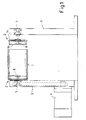
- the slitting and winding machine shown in detail in Figure 1 is used for winding webs, in particular of plastic films or metal foils, to bobbins.
- the webs are wound on sleeves 1, which are held at both ends of a retracted into the sleeve 1 chuck 2 during winding.
- Each chuck 2 is rotatably mounted on a winding lever 3.
- the rotary drive is an electric motor 4 which is fastened to one of the winding levers 3.
- the required torque is introduced into the chuck 2.
- Wound cutting and winding machines must be able to wind on sleeves 1 with different inner diameters.
- the clamping heads 2 When changing the sleeve format, the clamping heads 2 must be replaced with clamping heads 2 with adapted outer diameter. The replacement of the clamping heads 2 should be possible quickly and without much effort, it is essential that even at high speeds an exact concentricity of the sleeve 1 is guaranteed.
- a shaft journal 5 is rotatably mounted, on which the clamping head 2 is pushed, which has an adapted designed central bore 6.
- the clamping head 2 is a so-called expansion clamping head whose outer surface is formed by a plurality of tubular segment-shaped clamping jaws 10 which are mounted radially displaceable.
- three clamping jaws 10 are arranged circumferentially around the carrier 7.
- the carrier hub 7 has a plurality of outer surfaces 11, which are curved concavely in cross-section in example 6, on which the clamping jaws 10 are supported.
- the clamping jaws 10 are each supported by supporting elements which slide or roll on the outer surfaces 11.
- Gliding cylinders 12 are preferably mounted protruding radially inwards in the inside of each clamping jaw 10, which slide or roll on a concave outer surface 11 and change their spacing and thus also the spacing of the clamping jaws 10 from the center of rotation 13 of the clamping head 2 ,
- each sliding cylinder 12 is rotatably mounted in a clamping jaw 11.
- each clamping jaw 10 has two sliding cylinders 12, which are arranged at a distance from each other on a separate outer surface 11 are circumferentially movable. The curvatures of the outer surfaces 11 are so designed that all jaws 10 move in a rotary relative movement of the support 7 by the same amount only in the radial direction.
- Each clamping head 2 has at its the winding lever 3 facing outside a flange 14, which is mounted on the one hand limited rotatably mounted on the support hub 7, on the other hand rotationally fixed to each jaw 10 is connected.
- the rotationally fixed connection is effected in the exemplary embodiment in each case by a guide pin 15 which projects into a slide guide introduced into the 10 sliding guide, so that only a radial, but no circumferential relative movement of the clamping jaw 10 is possible.
- the clamping jaws 11 themselves or at least one sliding cylinder 12 per clamping jaw 11 can be made longer and protrude with its end into an inserted into the inside of the flanged wheel 14 slotted guide to prevent a circumferential relative movement.
- a disc-shaped cover 16 On the inside of the clamping head 2 is closed by a disc-shaped cover 16 which is screwed by means of screws 17 to the carrier 7. In the center of the lid 16 is a through hole 18 through which a tool for tightening and loosening the clamping screw 8 can be moved.
- the invention offers the great advantage that clamping heads 2 with different diameters and different immersion depths - ie different clamping head widths - can easily be fastened on the shaft journal 5 for different sleeves.
- the different clamping heads 2 have a uniform polygon bore 6, so that they can be fastened on the same shaft journal 5.
- a uniform polygonal connection between the carrier hub 7 and the shaft journal 5 mounted on the winding lever 3 is used for all clamping heads 2.
Landscapes
- Winding Of Webs (AREA)
- Winding, Rewinding, Material Storage Devices (AREA)
Abstract
Description
- Die Erfindung betrifft einen Spannkopf für eine Rollenschneid- und Wickelmaschine und eine Rollenschneid- und Wickelmaschine mit Wickelhebeln, an denen jeweils ein Spannkopf drehbar befestigt ist.
- Rollenschneid- und Wickelmaschinen dienen bekannter Weise zum Aufwickeln von Warenbahnen, insbesondere von Kunststofffolien und Metallfolien, zu Wickelrollen. Dabei werden die Bahnen auf Hülsen aufgewickelt, die an beiden Enden von einem in die Hülse eingefahrenen Spannkopf gehalten werden. Dazu ist jeder Spannkopf an einem Wickelhebel drehbar befestigt.
- Aus der
DE 33 29 330 A1 ist eine Spannvorrichtung für Wickelkeme bekannt, die mehrere in einem Käfig radial verstellbare rohrsegmentförmige Spannsegmente enthält, die um einen Zapfen mit gleichseitig-polygonalem Querschnitt angeordnet sind. Zwischen dem Zapfen und den Spannsegmenten sind drehbare Stützelemente angeordnet, von denen die Spannsegmente bei einem auf den Zapfen ausgeübten Drehmoment in radial Richtung nach außen in eine Spannstellung bewegt werden. - Rollenschneid- und Wickelmaschinen müssen so ausgerüstet sein, dass sie in der Lage sind, Hülsen mit unterschiedlichen Formaten zu verarbeiten. Bei einem Formatwechsei müssen die Maschinen möglichst schnell auf Spannköpfe mit geändertem Durchmesser umgerüstet werden.
- Der Erfindung liegt die Aufgabe zu Grunde, einen Spannkopf bereitzustellen, der schnell auszuwechseln ist, auch bei hohen Arbeitsgeschwindigkeiten der Rollenschneid- und Wickelmaschinen einen exakten Rundlauf der Hülse garantiert und der in der Lage ist, auch Hülsen mit leicht variierendem Innendurchmesser selbsttätig zu spannen und zu zentrieren.
- Diese Aufgabe wird mit den Merkmalen des Patentanspruchs 1 gelöst.
- Die Ausgestaltung des Spannkopfs mit einer zentralen Tragnabe, die eine als Polygon-Naben-Profil gestaltete Bohrung aufweist, ermöglicht es, den Spannkopf einfach auf ein im Profil entsprechend gestalteten und an den Wickelhebel befestigten Wellenzapfen aufzuschieben und dort zu befestigen. Bevorzugt werden von einem gleichseitigen Dreieck abgeleitete Polygon-Profile sowohl für die Tragnabe als auch für den Wellenzapfen verwendet. Die Polygon-Verbindung hat den Vorteil, dass bei Einleitung eines Drehmoments das Spiel zwischen der Tragnabe und dem Wellenzapfen durch eine geringfügige Drehung eliminiert und so der Spannkopf ideal auf dem Wellenzapfen zentriert wird.
- Nach einer bevorzugten Ausführungsform erfolgt die Befestigung des Spannkopfes an dem Wellenzapfen mittels einer zentralen Spannschraube, die sich durch die polygonförmige Bohrung in der Tragenabe erstreckt und in einer im Zentrum des Wellenzapfens eingebrachten Gewindebohrung festgeschraubt wird. So lässt sich der Spannkopf sehr einfach von dem Wellenzapfen lösen, da die Spannschraube den Spannkopf beim Aufdrehen in axialer Richtung von dem Wellenzapfen wegdrückt.
- Nach einer weiteren bevorzugten Ausführungsform weist die Tragnabe mehrere konkav gekrümmt verlaufende Außenflächen auf, und in der Innenseite jeder Spannbacke sind Gleitzylinder radial nach innen überstehend gelagert, die jeweils auf einer konkaven Außenfläche gleiten oder abrollen und dabei den Abstand der Spannbacken vom Drehzentrum des Spannkopfs verändern. Bevorzugt weist jede Spannbacke zwei Gleitzylinder auf, die mit Abstand voneinander angeordnet jeweils auf einer Außenfläche umfänglich bewegbar sind. Die Krümmungen der Außenflächen sind so gestaltet, dass sich alle Spannbacken bei einer rotativen Relativbewegung der Tragnabe um den gleichen Betrag in radialer Richtung bewegen. So werden die Spannköpfe beim Aufspannen exakt zentriert.
- Nach einer weiteren vorteilhaften Ausgestaltung der Erfindung weist jeder Spannkopf an seiner Außenseite eine Bordscheibe auf, die einerseits begrenzt drehbar auf der Tragnabe gelagert ist, andererseits rotationsfest mit jeder Spannbacke verbunden ist. Die rotationsfeste Verbindung zwischen der Bordscheibe und den Spannbacken bewirkt deren radiale Expansion bei einer Drehung der Bordscheibe durch eine Hülse. So ist die radiale Expansion der Spannbacken auch gewährleistet, wenn diese nicht an der Innenseite der Hülsen anliegen.
- Nachfolgend wird die Erfindung anhand eines bevorzugten Ausführungsbeispiels näher erläutert,
- Figur 1
- zeigt in einem Schnitt quer zur Bahnlaufrichtung einen Ausschnitt aus einer Rollenschneid- und Wickelmaschine.
- Figur 2
- zeigt einen Längsschnitt durch einen erfindungsgemäßen Spannkopf,
- Figur 3
- zeigt einen Querschnitt in expandierter Form, also bei maximalem Spannbackendurchmesser und
- Figur 4
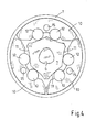
- zeigt einen Querschnitt in nicht expandierter Form, also bei minimalem Spannbackendurchmesser.
- Die in Figur 1 ausschnittsweise dargestellte Rollenschneid- und Wickelmaschine dient zum Aufwickeln von Warenbahnen, insbesondere von Kunststofffolien oder Metallfolien, zu Wickelrollen. Die Bahnen werden auf Hülsen 1 aufgewickelt, die beim Aufwickeln jeweils an beiden Enden von einem in die Hülse 1 eingefahrenen Spannkopf 2 gehalten werden. Jeder Spannkopf 2 ist drehbar an einem Wickelhebel 3 befestigt. Zum Drehen der Hülse 1 für das Aufwickeln ist zumindest einer der beiden Spannköpfe 2 mit einem Drehantrieb verbunden. Im Ausführungsbeispiel ist der Drehantrieb ein Elektromotor.4, der an einem der Wickelhebel 3 befestigt wird. Über den Elektromotor 4 wird das erforderliche Drehmoment in den Spannkopf 2 eingeleitet.
- Rollenschneid- und Wickelmaschinen müssen auf Hülsen 1 mit unterschiedlichem Innendurchmesser aufwickeln können. Bei einem Wechsel des Hülsenformats müssen die Spannköpfe 2 gegen Spannköpfe 2 mit angepasstem Außendurchmesser ausgewechselt werden. Das Auswechseln der Spannköpfe 2 soll schnell und ohne großen Aufwand möglich sein, dabei ist unabdingbar, dass auch bei hohen Arbeitsgeschwindigkeiten ein exakter Rundlauf der Hülse 1 garantiert ist. Dazu ist nach der Erfindung an jedem Wickelhebel 3 ein Wellenzapfen 5 drehbar gelagert, auf den der Spannkopf 2 aufgeschoben wird, der dazu eine angepasst gestaltete zentrale Bohrung 6 aufweist.
- Wie in Figur 3 dargestellt, befindet sich die Bohrung 6 in einer zentralen Tragnabe 7. Die Bohrung 6 ist als Polygon-Naben-Profil gestaltet. Entsprechend hat der Wellenzapfen 5 ein angepasstes Polygon-Wellen-Profil. Derartige Profile sind beispielsweise in der DIN 32 711 beschrieben. Bevorzugt werden von einem gleichseitigen Dreieck abgeleitete Polygon-Profile verwendet. Die erfindungsgemäße Polygon-Verbindung hat mehrere Vorteile:
- Zum einen ist ohne Anliegen eines Drehmoments ein geringes Spiel zwischen dem Wellenzapfen 5 und der Tragnabe 7 vorhanden, so dass sich ohne Anliegen eines Drehmoments der Spannkopf 2 einfach von dem Wellenzapfen 5 abziehen und auf diesen aufschieben lässt. Bei Einleitung eines Drehmoments wird das Spiel zwischen Tragnabe 7 und dem Wellenzapfen 5 durch eine geringfügige Drehung eliminiert, so dass der Spannkopf 2 ideal auf dem Wellenzapfen 5 zentriert wird. Die Befestigung des Spannkopfes 2 an dem Wellenzapfen 5 erfolgt mittels einer zentralen Spannschraube 8, die von außen zunächst durch ein zentrales Durchgangsloch in der Tragnabe 7 geführt wird, anschließend sich durch die polygonförmige Bohrung 6 erstreckt und in einer im Zentrum des Wellenzapfens 5 eingebrachten Gewindebohrung 9 festgeschraubt wird. Ober die Spannschraube 8 lässt sich so der Spannkopf 2 sehr einfach lösen, da diese den Spannkopf 2 beim Aufdrehen in axialer Richtung von dem Wellenzapfen 5 wegdrückt. Zugleich fixiert die Spannschraube 8 beim Festschrauben den Spannkopf 2 in axialer Richtung auf dem Wellenzapfen 5.
- Der Spannkopf 2 ist ein so genannter Expansionsspannkopf, dessen Außenfläche von mehreren rohrsegmentförmigen Spannbacken 10 gebildet wird, die radial verschiebbar gelagert sind. Bevorzugt sind drei Spannbacken 10 umfänglich um die Tragnabe 7 angeordnet. Damit sich die Spannbacken 10 bei einer umfänglichen Relativbewegung zu der Tragnabe 7 radial verschiebt, weist die Tragnabe 7 mehrere - in Beispiel 6- im Querschnitt konkav gekrümmt verlaufende Außenflächen 11 auf, auf denen die Spannbacken 10 abgestützt werden. Bevorzugt werden die Spannbacken 10 jeweils von Stützelementen abgestützt, die auf den Außenflächen 11 gleiten oder abrollen. Bevorzugt sind als Stützelemente Gleitzylinder 12 in der Innenseite jeder Spannbacke 10 radial nach innen überstehend gelagert, die jeweils auf einer konkaven Außenfläche 11 gleiten oder abrollen und eine Spannbacke 10 abstützend ihren Abstand und somit auch den Abstand der Spannbacken 10 vom Drehzentrum 13 des Spannkopfs 2 verändern. Im Ausführungsbeispiel ist jeder Gleitzylinder 12 drehbar in einer Spannbacke 11 gelagert. Bevorzugt weist jede Spannbacke 10 zwei Gleitzylinder 12 auf, die mit Abstand voneinander angeordnet jeweils auf einer eigenen Außenfläche 11 umfänglich bewegbar sind. Die Krümmungen der Außenflächen 11 sind dabei so gestaltet, dass sich alle Spannbacken 10 bei einer rotativen Relativbewegung der Tragnabe 7 um den gleichen Betrag ausschließlich in radialer Richtung bewegen.
- Jeder Spannkopf 2 weist an seiner den Wickelhebel 3 zugewandeten Außenseite eine Bordscheibe 14 auf, die einerseits begrenzt drehbar auf der Tragnabe 7 gelagert ist, andererseits rotationsfest mit jeder Spannbacke 10 verbunden ist. Die rotationsfeste Verbindung wird im Ausführungsbeispiel jeweils durch einen Kulissenstift 15 bewirkt, der so in eine in die Spannbacke 10 eingebrachte Kulissenführung ragt, so dass nur eine radiale, jedoch keine umfängliche Relativbewegung der Spannbacke 10 möglich ist. Alternativ können auch die Spannbacken 11 selbst oder zumindest ein Gleitzylinder 12 je Spannbacke 11 verlängert ausgeführt sein und mit ihrem Ende in eine in die Innenseite der Bordscheibe 14 eingebrachte Kulissenführung ragen, um eine umfängliche Relativbewegung zu verhindern. Die rotationsfeste Verbindung zwischen der Bordscheibe 14 und den Spannbacken 10 bewirkt deren radiale Expansion, sobald eine Hülse 1 an der Bordscheibe 14 anliegt und diese dreht. Ein Anliegen der Spannbacken 10 an der Innenseite der Hülse 11 ist somit nach dem Aufschieben der Hülsen 1 zu Beginn der Drehung nicht erforderlich, um die radiale Expansion der Spannbacken 10 zu bewirken.
- An der Innenseite ist der Spannkopf 2 von einem scheibenförmigen Deckel 16 abgeschlossen, der mittels Schrauben 17 an der Tragnabe 7 festgeschraubt ist. Im Zentrum des Deckels 16 befindet sich eine Durchgangsbohrung 18, durch die ein Werkzeug zum Festschrauben und Lösen der Spannschraube 8 bewegt werden kann.
- Die Erfindung bietet den großen Vorteil, dass Spannköpfe 2 mit unterschiedlichem Durchmesser und unterschiedlichen Eintauchtiefen - also unterschiedlichen Spannkopfbreiten - für verschiedene Hülsen einfach auf dem Wellenzapfen 5 befestigt werden können. Die unterschiedlichen Spannköpfe 2 weisen dazu eine einheitliche Polygonbohrung 6 auf, so dass sie auf demselben Wellenzapfen 5 befestigt werden können. Es wird somit für alle Spannköpfe 2 eine einheitliche Polygon-Verbindung zwischen Tragnabe 7 und dem an dem Wickelhebel 3 gelagerten Wellenzapfen 5 verwendet.
Claims (9)
- Spannkopf für eine Rollenschneid- und Wickelmaschine mit mehreren radial verschiebbar gelagerten Spannbacken (10), die auf gekrümmten Laufflächen abgestützt werden, gekennzeichnet durch eine zentrale Tragnabe (7), die eine als Polygon-Naben-Profil gestaltete zentrale Bohrung (6) enthält und gekrümmt verlaufende Außenflächen (11) aufweist, auf denen die Spannbacken (10) abgestützt werden.
- Spannkopf nach Anspruch 1, dadurch gekennzeichnet, dass die Bohrung (6) ein von einem gleichseitigen Dreieck abgeleitetes Polygon-Profil aufweist.
- Spannkopf nach Anspruch 1 oder 2, dadurch gekennzeichnet, dass die Tragnabe (7) mehrere konkav gekrümmte Außenflächen (11) aufweist.
- Spannkopf nach einem der Ansprüche 1 bis 3, dadurch gekennzeichnet, dass die Spannbacken (10) von Stützelementen abgestützt werden, die auf den Außenflächen (11) gleiten oder abrollen.
- Spannkopf nach Anspruch 4, dadurch gekennzeichnet, dass als Stützelemente Gleitzylinder (12) in den Spannbacken (10) gelagert sind.
- Spannkopf nach Anspruch 5 , dadurch gekennzeichnet, dass jede Spannbacke (10) zwei Gleitzyünder (12) aufweist, die jeweils auf einer eigenen Außenfläche (11) der Tragnabe (7) umfänglich bewegbar gelagert sind.
- Spannkopf nach einem der Ansprüche 1 bis 6, gekennzeichnet durch eine Bordscheibe (14), die begrenzt drehbar auf der Tragnabe (7) gelagert und rotationsfest mit jeder Spannbacke (10) verbunden sind.
- Rollenschneid- und Wickelmaschine mit Wickelhebeln (3), an denen jeweils ein Spannkopf (2) drehbar befestigbar ist, dadurch gekennzeichnet, dass an einem Wickelhebel (3) ein Wellenzapfen (5) drehbar gelagert ist, auf den ein Spannkopf (2) gemäß einem der Ansprüche 1 bis 7 aufschiebbar ist, wobei der Wellenzapfen (5) ein der Bohrung (6) angepasstes Polygon-Wellen-Profil aufweist.
- Rollenschneid- und Wickelmaschine nach Anspruch 8, dadurch gekennzeichnet, dass die Befestigung des Spannkopfs (2) an dem Wellenzapfen (5) mittels einer zentralen Spannschraube (8) erfolgt, die durch die polygonförmige Bohrung (6) in der Tragnabe (7) geführt und in einer im Zentrum des Wellenzapfens (5) eingebrachten Gewindebohrung (9) festgeschraubt ist.
Applications Claiming Priority (1)
| Application Number | Priority Date | Filing Date | Title |
|---|---|---|---|
| DE102005021077A DE102005021077A1 (de) | 2005-05-06 | 2005-05-06 | Spannkopf für eine Rollenschneid- und Wickelmaschine |
Publications (3)
| Publication Number | Publication Date |
|---|---|
| EP1719725A2 true EP1719725A2 (de) | 2006-11-08 |
| EP1719725A3 EP1719725A3 (de) | 2007-08-29 |
| EP1719725B1 EP1719725B1 (de) | 2011-10-12 |
Family
ID=36729246
Family Applications (1)
| Application Number | Title | Priority Date | Filing Date |
|---|---|---|---|
| EP06009134A Expired - Lifetime EP1719725B1 (de) | 2005-05-06 | 2006-05-03 | Spannkopf für eine Rollenschneid- und Wickelmaschine |
Country Status (4)
| Country | Link |
|---|---|
| US (1) | US7540448B2 (de) |
| EP (1) | EP1719725B1 (de) |
| AT (1) | ATE528237T1 (de) |
| DE (1) | DE102005021077A1 (de) |
Cited By (4)
| Publication number | Priority date | Publication date | Assignee | Title |
|---|---|---|---|---|
| ITMI20091539A1 (it) * | 2009-09-07 | 2011-03-08 | Andrea Ciani | Trascinatore meccanico autoespandente |
| CN112645157A (zh) * | 2020-12-31 | 2021-04-13 | 张家港市弘扬机械设备有限公司 | 一种芯筒卡装用的多级卡装装置 |
| CN114314086A (zh) * | 2021-12-20 | 2022-04-12 | 上海韩东机械科技有限公司 | 自涨式机械夹头及工作方法 |
| CN114933215A (zh) * | 2022-05-31 | 2022-08-23 | 嘉兴市朱氏塑料五金有限公司 | 一种软管收卷绕膜下料一体机 |
Families Citing this family (8)
| Publication number | Priority date | Publication date | Assignee | Title |
|---|---|---|---|---|
| WO2005073114A2 (de) * | 2004-01-30 | 2005-08-11 | Koenig & Bauer Aktiengesellschaft | Antrieb eines rollenwechslers |
| KR100889320B1 (ko) * | 2007-03-05 | 2009-03-18 | 주식회사 하이닉스반도체 | 반도체 메모리 소자 |
| CN102807137B (zh) * | 2012-08-13 | 2015-05-20 | 浙江仙鹤特种纸有限公司 | 外径可变的卷纸辊 |
| US9770142B2 (en) * | 2013-12-02 | 2017-09-26 | Dispensing Dynamics International, Llc | Multi-piece support for paper roll product |
| CN112456198A (zh) * | 2019-09-09 | 2021-03-09 | 广西真龙实业有限责任公司 | 一种纸芯盘紧器 |
| IT202000019768A1 (it) * | 2020-08-07 | 2022-02-07 | Re S P A Controlli Ind | Espulsore pneumatico lineare del tipo collegabile ad un braccio di uno svolgitore a bracci mobili |
| IT202000019792A1 (it) * | 2020-08-07 | 2022-02-07 | Re S P A Controlli Ind | Kit di installazione per un espulsore pneumatico lineare del tipo collegabile ad un braccio di uno svolgitore a bracci mobili |
| IT202000019849A1 (it) * | 2020-08-10 | 2022-02-10 | Renova S R L | Mandrino di supporto per bobine di materiale avvolgibile |
Family Cites Families (20)
| Publication number | Priority date | Publication date | Assignee | Title |
|---|---|---|---|---|
| US2211472A (en) * | 1938-03-02 | 1940-08-13 | Clarence J Klein | Reel structure |
| US3007652A (en) * | 1959-12-03 | 1961-11-07 | John A Heckman | Paper roll mounting mechanism |
| CH392193A (de) * | 1961-02-27 | 1965-05-15 | Faerberei Und Appretur Schuste | Vorrichtung zum Aufspannen von Papphülsen auf den Wickelstab bei von der Rolle arbeitenden Maschinen |
| NO133832C (de) * | 1966-10-13 | 1976-07-07 | Sonoco Products Co | |
| US3815836A (en) * | 1971-02-11 | 1974-06-11 | Barmag Barmer Maschf | Sleeve chuck for thread winding device |
| US3963250A (en) * | 1972-04-03 | 1976-06-15 | Double E Company, Inc. | Chuck |
| US3993317A (en) * | 1974-12-12 | 1976-11-23 | Double E Company, Inc. | Core chuck |
| DE2526497B1 (de) * | 1975-06-13 | 1976-11-25 | Ahlstroem Dev Gmbh | Spannkopf fuer die Kernrohre von Wickeln aus Papier,Kunststoffolien o.dgl. |
| DE2612375C2 (de) | 1976-03-24 | 1983-04-14 | A. Ahlström Development GmbH, 7315 Weilheim | Spannkopf für die die Kernrohre von Wickeln aus Papier, Kunststoffolien oder dergleichen |
| US4193633A (en) * | 1977-12-16 | 1980-03-18 | Double E Company, Inc. | Core chuck |
| FR2438694A1 (fr) * | 1978-10-13 | 1980-05-09 | Rhone Poulenc Textile | Broche de renvidage de fils textiles |
| DE2929934C2 (de) * | 1979-07-24 | 1982-02-11 | Jagenberg-Werke AG, 4000 Düsseldorf | Vorrichtung zum Aufspannen von rohrförmigen Wickelkernen |
| DE7930223U1 (de) * | 1979-10-25 | 1980-04-30 | Heidemanns, Peter, 4150 Krefeld | Wickelstange zum aufwickeln von insbesondere baendern und warenbahnen |
| JPS58200719A (ja) * | 1982-05-19 | 1983-11-22 | 小林 昌志 | トイレツトペ−パロ−ル及びその製造法 |
| US4519620A (en) * | 1983-03-16 | 1985-05-28 | Double E Company Inc. | Core chuck with resilient rollers |
| DE3329330C2 (de) * | 1983-08-13 | 1986-10-02 | Jagenberg AG, 4000 Düsseldorf | Spannvorrichtung für Wickelkerne |
| US5524849A (en) * | 1990-05-23 | 1996-06-11 | Beloit Technologies, Inc. | Clamping head for winding tubes |
| CA2083815C (en) * | 1990-05-26 | 1996-04-23 | Jurgen Treutner | Clamping head for winding tubes |
| US6367733B1 (en) * | 1998-12-02 | 2002-04-09 | Mclaughlin James | Core chuck |
| US7077356B2 (en) * | 2003-06-19 | 2006-07-18 | Hope Harry L | Core chuck |
-
2005
- 2005-05-06 DE DE102005021077A patent/DE102005021077A1/de not_active Ceased
-
2006
- 2006-05-02 US US11/415,941 patent/US7540448B2/en not_active Expired - Fee Related
- 2006-05-03 EP EP06009134A patent/EP1719725B1/de not_active Expired - Lifetime
- 2006-05-03 AT AT06009134T patent/ATE528237T1/de active
Cited By (4)
| Publication number | Priority date | Publication date | Assignee | Title |
|---|---|---|---|---|
| ITMI20091539A1 (it) * | 2009-09-07 | 2011-03-08 | Andrea Ciani | Trascinatore meccanico autoespandente |
| CN112645157A (zh) * | 2020-12-31 | 2021-04-13 | 张家港市弘扬机械设备有限公司 | 一种芯筒卡装用的多级卡装装置 |
| CN114314086A (zh) * | 2021-12-20 | 2022-04-12 | 上海韩东机械科技有限公司 | 自涨式机械夹头及工作方法 |
| CN114933215A (zh) * | 2022-05-31 | 2022-08-23 | 嘉兴市朱氏塑料五金有限公司 | 一种软管收卷绕膜下料一体机 |
Also Published As
| Publication number | Publication date |
|---|---|
| US20070040060A1 (en) | 2007-02-22 |
| ATE528237T1 (de) | 2011-10-15 |
| EP1719725A3 (de) | 2007-08-29 |
| US7540448B2 (en) | 2009-06-02 |
| EP1719725B1 (de) | 2011-10-12 |
| DE102005021077A1 (de) | 2006-11-09 |
Similar Documents
| Publication | Publication Date | Title |
|---|---|---|
| DE10125761B4 (de) | Vorrichtung zur Aufnahme einer einen aufgewickelten Bandstreifen aufweisenden Vorratsrolle, insbesondere einer Etikettenvorratsrolle und Vorrichtung zum Bedrucken eines Bandstreifens oder von auf einem Bandstreifen haftenden Etiketten | |
| EP2178675B1 (de) | Schnellwechselsystem | |
| EP1719725B1 (de) | Spannkopf für eine Rollenschneid- und Wickelmaschine | |
| DE7535872U (de) | Expansionsdorn | |
| EP2285718B1 (de) | Rollenwechsler mit einer aufnahme zur lagerung einer materialrolle mit einer wickelhülse | |
| EP2747922B1 (de) | Vorrichtung und verfahren zum spannen eines bauteils an einem rotierenden maschinenteil | |
| DE2341059C2 (de) | Spann-Wickeldorn | |
| EP1997757B1 (de) | Rollenwechsler mit einem Spannkonus zur Aufnahme von einer aufgewickelten Materialrolle tragenden Hülse | |
| DE69209297T2 (de) | Spreizbarer spanndorn | |
| EP3117916B1 (de) | Vorrichtung zum bearbeiten eines rohres | |
| EP1509468B1 (de) | Mitnehmerelement | |
| DE102005004558A1 (de) | Vorrichtung und Verfahren zur wellenlosen Halterung von Wickelhülsen | |
| DE2932580A1 (de) | Vorrichtung zur befestigung einer spreizbaren nabe in einer bohrung | |
| EP3802386A1 (de) | Hülse, wickeleinrichtung und verfahren zum mehrfachen, aufeinanderfolgenden aufwickeln von bahnen zu materialwickeln | |
| DE10224839B4 (de) | Spanndorn | |
| DE2211518A1 (de) | Vorrichtung zum aufspannen von rohrfoermigen wickelkernen | |
| EP1356481B1 (de) | Verfahren zum bewickeln eines ringkerns | |
| DE102008000065B4 (de) | Spannkonus zur Aufnahme einer auf eine Wickelhülse aufgewickelten Materialrolle | |
| EP0369498A2 (de) | Einrichtung zum Haltern | |
| DE2618652A1 (de) | Kern-spannvorrichtung | |
| DE2910114A1 (de) | Spannkopf fuer die kernrohre von wickeln aus papier, kunststoff u.dgl. | |
| DE102007012192B4 (de) | Spannkonus zur wellenlosen Halterung von Wickelhülsen | |
| DE2638724A1 (de) | Aufwickelmaschine fuer die gehaeusekurzschluss-schutzisolation von polspulen elektrischer maschinen | |
| EP2314395B1 (de) | Vorrichtung und Verfahren zum Umformen von Werkstücken | |
| DE102010038409A1 (de) | Vorrichtung zur Aufnahme einer Altdrahtspule |
Legal Events
| Date | Code | Title | Description |
|---|---|---|---|
| PUAI | Public reference made under article 153(3) epc to a published international application that has entered the european phase |
Free format text: ORIGINAL CODE: 0009012 |
|
| AK | Designated contracting states |
Kind code of ref document: A2 Designated state(s): AT BE BG CH CY CZ DE DK EE ES FI FR GB GR HU IE IS IT LI LT LU LV MC NL PL PT RO SE SI SK TR |
|
| AX | Request for extension of the european patent |
Extension state: AL BA HR MK YU |
|
| PUAL | Search report despatched |
Free format text: ORIGINAL CODE: 0009013 |
|
| AK | Designated contracting states |
Kind code of ref document: A3 Designated state(s): AT BE BG CH CY CZ DE DK EE ES FI FR GB GR HU IE IS IT LI LT LU LV MC NL PL PT RO SE SI SK TR |
|
| AX | Request for extension of the european patent |
Extension state: AL BA HR MK YU |
|
| 17P | Request for examination filed |
Effective date: 20080229 |
|
| AKX | Designation fees paid |
Designated state(s): AT BE BG CH CY CZ DE DK EE ES FI FR GB GR HU IE IS IT LI LT LU LV MC NL PL PT RO SE SI SK TR |
|
| 17Q | First examination report despatched |
Effective date: 20080424 |
|
| GRAP | Despatch of communication of intention to grant a patent |
Free format text: ORIGINAL CODE: EPIDOSNIGR1 |
|
| GRAS | Grant fee paid |
Free format text: ORIGINAL CODE: EPIDOSNIGR3 |
|
| GRAA | (expected) grant |
Free format text: ORIGINAL CODE: 0009210 |
|
| AK | Designated contracting states |
Kind code of ref document: B1 Designated state(s): AT BE BG CH CY CZ DE DK EE ES FI FR GB GR HU IE IS IT LI LT LU LV MC NL PL PT RO SE SI SK TR |
|
| REG | Reference to a national code |
Ref country code: GB Ref legal event code: FG4D Free format text: NOT ENGLISH |
|
| REG | Reference to a national code |
Ref country code: CH Ref legal event code: EP |
|
| REG | Reference to a national code |
Ref country code: IE Ref legal event code: FG4D |
|
| REG | Reference to a national code |
Ref country code: DE Ref legal event code: R096 Ref document number: 502006010368 Country of ref document: DE Effective date: 20111208 |
|
| REG | Reference to a national code |
Ref country code: NL Ref legal event code: VDEP Effective date: 20111012 |
|
| LTIE | Lt: invalidation of european patent or patent extension |
Effective date: 20111012 |
|
| PG25 | Lapsed in a contracting state [announced via postgrant information from national office to epo] |
Ref country code: IS Free format text: LAPSE BECAUSE OF FAILURE TO SUBMIT A TRANSLATION OF THE DESCRIPTION OR TO PAY THE FEE WITHIN THE PRESCRIBED TIME-LIMIT Effective date: 20120212 Ref country code: LT Free format text: LAPSE BECAUSE OF FAILURE TO SUBMIT A TRANSLATION OF THE DESCRIPTION OR TO PAY THE FEE WITHIN THE PRESCRIBED TIME-LIMIT Effective date: 20111012 |
|
| PGFP | Annual fee paid to national office [announced via postgrant information from national office to epo] |
Ref country code: IE Payment date: 20120321 Year of fee payment: 7 |
|
| REG | Reference to a national code |
Ref country code: IE Ref legal event code: FD4D |
|
| PG25 | Lapsed in a contracting state [announced via postgrant information from national office to epo] |
Ref country code: PT Free format text: LAPSE BECAUSE OF FAILURE TO SUBMIT A TRANSLATION OF THE DESCRIPTION OR TO PAY THE FEE WITHIN THE PRESCRIBED TIME-LIMIT Effective date: 20120213 Ref country code: SE Free format text: LAPSE BECAUSE OF FAILURE TO SUBMIT A TRANSLATION OF THE DESCRIPTION OR TO PAY THE FEE WITHIN THE PRESCRIBED TIME-LIMIT Effective date: 20111012 Ref country code: NL Free format text: LAPSE BECAUSE OF FAILURE TO SUBMIT A TRANSLATION OF THE DESCRIPTION OR TO PAY THE FEE WITHIN THE PRESCRIBED TIME-LIMIT Effective date: 20111012 Ref country code: LV Free format text: LAPSE BECAUSE OF FAILURE TO SUBMIT A TRANSLATION OF THE DESCRIPTION OR TO PAY THE FEE WITHIN THE PRESCRIBED TIME-LIMIT Effective date: 20111012 Ref country code: SI Free format text: LAPSE BECAUSE OF FAILURE TO SUBMIT A TRANSLATION OF THE DESCRIPTION OR TO PAY THE FEE WITHIN THE PRESCRIBED TIME-LIMIT Effective date: 20111012 Ref country code: GR Free format text: LAPSE BECAUSE OF FAILURE TO SUBMIT A TRANSLATION OF THE DESCRIPTION OR TO PAY THE FEE WITHIN THE PRESCRIBED TIME-LIMIT Effective date: 20120113 |
|
| PG25 | Lapsed in a contracting state [announced via postgrant information from national office to epo] |
Ref country code: CY Free format text: LAPSE BECAUSE OF FAILURE TO SUBMIT A TRANSLATION OF THE DESCRIPTION OR TO PAY THE FEE WITHIN THE PRESCRIBED TIME-LIMIT Effective date: 20111012 |
|
| PG25 | Lapsed in a contracting state [announced via postgrant information from national office to epo] |
Ref country code: SK Free format text: LAPSE BECAUSE OF FAILURE TO SUBMIT A TRANSLATION OF THE DESCRIPTION OR TO PAY THE FEE WITHIN THE PRESCRIBED TIME-LIMIT Effective date: 20111012 Ref country code: BG Free format text: LAPSE BECAUSE OF FAILURE TO SUBMIT A TRANSLATION OF THE DESCRIPTION OR TO PAY THE FEE WITHIN THE PRESCRIBED TIME-LIMIT Effective date: 20120112 Ref country code: CZ Free format text: LAPSE BECAUSE OF FAILURE TO SUBMIT A TRANSLATION OF THE DESCRIPTION OR TO PAY THE FEE WITHIN THE PRESCRIBED TIME-LIMIT Effective date: 20111012 Ref country code: DK Free format text: LAPSE BECAUSE OF FAILURE TO SUBMIT A TRANSLATION OF THE DESCRIPTION OR TO PAY THE FEE WITHIN THE PRESCRIBED TIME-LIMIT Effective date: 20111012 Ref country code: EE Free format text: LAPSE BECAUSE OF FAILURE TO SUBMIT A TRANSLATION OF THE DESCRIPTION OR TO PAY THE FEE WITHIN THE PRESCRIBED TIME-LIMIT Effective date: 20111012 Ref country code: IE Free format text: LAPSE BECAUSE OF FAILURE TO SUBMIT A TRANSLATION OF THE DESCRIPTION OR TO PAY THE FEE WITHIN THE PRESCRIBED TIME-LIMIT Effective date: 20111012 |
|
| PLBE | No opposition filed within time limit |
Free format text: ORIGINAL CODE: 0009261 |
|
| STAA | Information on the status of an ep patent application or granted ep patent |
Free format text: STATUS: NO OPPOSITION FILED WITHIN TIME LIMIT |
|
| PG25 | Lapsed in a contracting state [announced via postgrant information from national office to epo] |
Ref country code: PL Free format text: LAPSE BECAUSE OF FAILURE TO SUBMIT A TRANSLATION OF THE DESCRIPTION OR TO PAY THE FEE WITHIN THE PRESCRIBED TIME-LIMIT Effective date: 20111012 Ref country code: RO Free format text: LAPSE BECAUSE OF FAILURE TO SUBMIT A TRANSLATION OF THE DESCRIPTION OR TO PAY THE FEE WITHIN THE PRESCRIBED TIME-LIMIT Effective date: 20111012 |
|
| 26N | No opposition filed |
Effective date: 20120713 |
|
| REG | Reference to a national code |
Ref country code: DE Ref legal event code: R097 Ref document number: 502006010368 Country of ref document: DE Effective date: 20120713 |
|
| BERE | Be: lapsed |
Owner name: KAMPF G.M.B.H. & CO. MASCHINENFABRIK Effective date: 20120531 |
|
| PG25 | Lapsed in a contracting state [announced via postgrant information from national office to epo] |
Ref country code: MC Free format text: LAPSE BECAUSE OF NON-PAYMENT OF DUE FEES Effective date: 20120531 |
|
| REG | Reference to a national code |
Ref country code: CH Ref legal event code: PL |
|
| PG25 | Lapsed in a contracting state [announced via postgrant information from national office to epo] |
Ref country code: LI Free format text: LAPSE BECAUSE OF NON-PAYMENT OF DUE FEES Effective date: 20120531 Ref country code: CH Free format text: LAPSE BECAUSE OF NON-PAYMENT OF DUE FEES Effective date: 20120531 |
|
| PG25 | Lapsed in a contracting state [announced via postgrant information from national office to epo] |
Ref country code: BE Free format text: LAPSE BECAUSE OF NON-PAYMENT OF DUE FEES Effective date: 20120531 |
|
| REG | Reference to a national code |
Ref country code: FR Ref legal event code: ST Effective date: 20130131 |
|
| PG25 | Lapsed in a contracting state [announced via postgrant information from national office to epo] |
Ref country code: ES Free format text: LAPSE BECAUSE OF FAILURE TO SUBMIT A TRANSLATION OF THE DESCRIPTION OR TO PAY THE FEE WITHIN THE PRESCRIBED TIME-LIMIT Effective date: 20120123 Ref country code: FR Free format text: LAPSE BECAUSE OF NON-PAYMENT OF DUE FEES Effective date: 20120531 |
|
| PG25 | Lapsed in a contracting state [announced via postgrant information from national office to epo] |
Ref country code: FI Free format text: LAPSE BECAUSE OF FAILURE TO SUBMIT A TRANSLATION OF THE DESCRIPTION OR TO PAY THE FEE WITHIN THE PRESCRIBED TIME-LIMIT Effective date: 20111012 |
|
| REG | Reference to a national code |
Ref country code: AT Ref legal event code: MM01 Ref document number: 528237 Country of ref document: AT Kind code of ref document: T Effective date: 20120503 |
|
| PG25 | Lapsed in a contracting state [announced via postgrant information from national office to epo] |
Ref country code: AT Free format text: LAPSE BECAUSE OF NON-PAYMENT OF DUE FEES Effective date: 20120503 |
|
| PG25 | Lapsed in a contracting state [announced via postgrant information from national office to epo] |
Ref country code: TR Free format text: LAPSE BECAUSE OF FAILURE TO SUBMIT A TRANSLATION OF THE DESCRIPTION OR TO PAY THE FEE WITHIN THE PRESCRIBED TIME-LIMIT Effective date: 20111012 |
|
| PG25 | Lapsed in a contracting state [announced via postgrant information from national office to epo] |
Ref country code: LU Free format text: LAPSE BECAUSE OF NON-PAYMENT OF DUE FEES Effective date: 20120503 |
|
| PG25 | Lapsed in a contracting state [announced via postgrant information from national office to epo] |
Ref country code: HU Free format text: LAPSE BECAUSE OF FAILURE TO SUBMIT A TRANSLATION OF THE DESCRIPTION OR TO PAY THE FEE WITHIN THE PRESCRIBED TIME-LIMIT Effective date: 20060503 |
|
| PGFP | Annual fee paid to national office [announced via postgrant information from national office to epo] |
Ref country code: GB Payment date: 20150521 Year of fee payment: 10 |
|
| PGFP | Annual fee paid to national office [announced via postgrant information from national office to epo] |
Ref country code: IT Payment date: 20150514 Year of fee payment: 10 |
|
| PG25 | Lapsed in a contracting state [announced via postgrant information from national office to epo] |
Ref country code: IE Free format text: LAPSE BECAUSE OF FAILURE TO SUBMIT A TRANSLATION OF THE DESCRIPTION OR TO PAY THE FEE WITHIN THE PRESCRIBED TIME-LIMIT Effective date: 20120420 |
|
| PGFP | Annual fee paid to national office [announced via postgrant information from national office to epo] |
Ref country code: DE Payment date: 20160525 Year of fee payment: 11 |
|
| GBPC | Gb: european patent ceased through non-payment of renewal fee |
Effective date: 20160503 |
|
| PG25 | Lapsed in a contracting state [announced via postgrant information from national office to epo] |
Ref country code: IT Free format text: LAPSE BECAUSE OF NON-PAYMENT OF DUE FEES Effective date: 20160503 |
|
| PG25 | Lapsed in a contracting state [announced via postgrant information from national office to epo] |
Ref country code: GB Free format text: LAPSE BECAUSE OF NON-PAYMENT OF DUE FEES Effective date: 20160503 |
|
| REG | Reference to a national code |
Ref country code: DE Ref legal event code: R119 Ref document number: 502006010368 Country of ref document: DE |
|
| PG25 | Lapsed in a contracting state [announced via postgrant information from national office to epo] |
Ref country code: DE Free format text: LAPSE BECAUSE OF NON-PAYMENT OF DUE FEES Effective date: 20171201 |