EP1719732B1 - Hubvorrichtung - Google Patents
Hubvorrichtung Download PDFInfo
- Publication number
- EP1719732B1 EP1719732B1 EP05009993A EP05009993A EP1719732B1 EP 1719732 B1 EP1719732 B1 EP 1719732B1 EP 05009993 A EP05009993 A EP 05009993A EP 05009993 A EP05009993 A EP 05009993A EP 1719732 B1 EP1719732 B1 EP 1719732B1
- Authority
- EP
- European Patent Office
- Prior art keywords
- scissor
- lifting device
- guide element
- goods receiving
- receiving device
- Prior art date
- Legal status (The legal status is an assumption and is not a legal conclusion. Google has not performed a legal analysis and makes no representation as to the accuracy of the status listed.)
- Expired - Lifetime
Links
Images

Classifications
-
- B—PERFORMING OPERATIONS; TRANSPORTING
- B66—HOISTING; LIFTING; HAULING
- B66F—HOISTING, LIFTING, HAULING OR PUSHING, NOT OTHERWISE PROVIDED FOR, e.g. DEVICES WHICH APPLY A LIFTING OR PUSHING FORCE DIRECTLY TO THE SURFACE OF A LOAD
- B66F7/00—Lifting frames, e.g. for lifting vehicles; Platform lifts
- B66F7/06—Lifting frames, e.g. for lifting vehicles; Platform lifts with platforms supported by levers for vertical movement
- B66F7/065—Scissor linkages, i.e. X-configuration
-
- B—PERFORMING OPERATIONS; TRANSPORTING
- B66—HOISTING; LIFTING; HAULING
- B66F—HOISTING, LIFTING, HAULING OR PUSHING, NOT OTHERWISE PROVIDED FOR, e.g. DEVICES WHICH APPLY A LIFTING OR PUSHING FORCE DIRECTLY TO THE SURFACE OF A LOAD
- B66F7/00—Lifting frames, e.g. for lifting vehicles; Platform lifts
- B66F7/06—Lifting frames, e.g. for lifting vehicles; Platform lifts with platforms supported by levers for vertical movement
- B66F7/0625—Lifting frames, e.g. for lifting vehicles; Platform lifts with platforms supported by levers for vertical movement with wheels for moving around the floor
-
- B—PERFORMING OPERATIONS; TRANSPORTING
- B66—HOISTING; LIFTING; HAULING
- B66F—HOISTING, LIFTING, HAULING OR PUSHING, NOT OTHERWISE PROVIDED FOR, e.g. DEVICES WHICH APPLY A LIFTING OR PUSHING FORCE DIRECTLY TO THE SURFACE OF A LOAD
- B66F9/00—Devices for lifting or lowering bulky or heavy goods for loading or unloading purposes
- B66F9/06—Devices for lifting or lowering bulky or heavy goods for loading or unloading purposes movable, with their loads, on wheels or the like, e.g. fork-lift trucks
Definitions
- the invention relates to a lifting device according to the preamble of claim 1.
- Such a lifting device is off US 5,829,948 known.
- Such lifting devices are known as so-called scissor lift tables or scissor lift trucks.
- Different designs as well as manual and motor-operated drives for these devices as well as their stationary and mobile use are state of the art and will not be discussed further below.
- the task solution is achieved in a surprisingly simple and economical manner.
- the invention consists in that, e.g. based on the sliding direction of a scissor lift truck, the scissor mechanism is arranged in the rear region of the scissor lift truck with a substantially transverse to the sliding direction pivoting plane, which should also be referred to as a transverse deviation of about 25 ° to the sliding direction.
- the lifting device on a scissors cross which is a very economical solution for small loads and small distances between the pivot plane and load center.
- the lifting device has two parallel spaced and aligned mutually arranged scissor crosses, which are connected by means of a common scissors axis and multiple horizontally arranged spacers.
- the lifting device is particularly suitable for versatile, mobile use, e.g. in shopping and material vehicles and forklift vehicles is suitable, in addition to the use as the above-described lifting device also primarily the volume reduction is sought, which makes it possible to carry inventively designed pallet trucks and vehicles in corresponding vehicles as loading and unloading space saving. It is also possible to use the invention also for stationary use, e.g. by anchoring the device on a hall floor, a loading dock or a vehicle loading area, the scissors-based lifting device for lifting, lowering and loading of loads can be advantageously used.
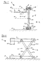
- a lifting device 1 for stationary use according to Figures 1 and 2 has a lower guide element 2 and an upper guide element 3, between which a scissor mechanism 4 stands up, which has a scissor cross 5.
- the scissor members 5.1, 5.2 of the scissors cross 5 are rotatably connected to each other by means of a common scissors axis 11.
- a goods receiving device 6 in the form of parallel spaced, angled forks 6.1, 6.2 is arranged, wherein the distance between the longitudinal axis L of the load forks 6.1, 6.2 is selected to the center line 28 so that the load forks 6.1, 6.2 with the greatest possible pivoting of the scissor members 5.1 , 5.2 on the footprint F are lowered.
- the longitudinal axis L extends from an end 8 which is fastened to the guide element 3 to a free end 9 of the goods receiving device 6.
- the free ends of the scissor members 5.1, 5.2 on one side via fixed hinge pins 12, 13 with the lower and upper guide element 2, 3 are pivotable connected.
- the scissors mechanism 4 is raised or lowered by a drive, not shown here.
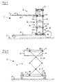
- 3 and 4 show a lifting device 1 which is fastened in the end region of a mobile frame 7, which is not described in more detail here, wherein the scissor mechanism 4 has two parallel spaced scissor assemblies 29 and 30, each of two superimposed, pivotally interconnected Scissor crosses 5, 16 and 17, 18 are formed.
- the lower and upper guide elements 2 and 3 are designed to receive two adjacent and parallel scissor crosses 5, 18 and 16, 17.
- the lower and upper free ends of the scissors crosses 5, 18 and 16, 17 are connected analogously to the illustration in Figures 1 and 2 by means of joint axes 12, 13 and rollers 14, 15 with the lower and upper guide elements 2 and 3 respectively , wherein to increase the stability between the opposite cutting and connecting points of the scissor assemblies 29, 30 spacers 19-23 are arranged.
- the arranged on the upper guide member 3 goods receiving device 6 is formed as an angled loading plate having a surface 10 for receiving loads.
- the goods receiving device 6 is - not shown here - detachably connected to the guide member 3 so that they after settling on a footprint F or any other footprint, e.g. the loading area of a vehicle can be decoupled from the guide element 3 or can be coupled from there to the guide element 3 again.
- FIG. 5 shows a simplified side view of a lifting device 1 carried along in a motor vehicle 24, which, similar to FIGS. 1 and 2, has only a scissors cross 5, but which is pivoted through 180 ° on an imaginary axis about the center line M, then the lower guide element 2 is now arranged on a traverse 26 movable in the passenger car combination 24 on linear guides 25 and a goods receiving device 6 in the form of a flat loading plate with a surface 10 for receiving load is held on the upper guide element 3.
- the position of the center lines 27, 28 shown in Figure 1 symbolically shows the position of the fixed hinge axes and the rollers.
Landscapes
- Engineering & Computer Science (AREA)
- Structural Engineering (AREA)
- Life Sciences & Earth Sciences (AREA)
- Geology (AREA)
- Mechanical Engineering (AREA)
- Transportation (AREA)
- Civil Engineering (AREA)
- Forklifts And Lifting Vehicles (AREA)
- Noodles (AREA)
- Advancing Webs (AREA)
- Electrical Discharge Machining, Electrochemical Machining, And Combined Machining (AREA)
- Earth Drilling (AREA)
- Conveying And Assembling Of Building Elements In Situ (AREA)
- Automatic Assembly (AREA)
Description
- Die Erfindung bezieht sich auf eine Hubvorrichtung nach dem Oberbegriff des Anspruchs 1.
- Eine solche Hubvorrichtung ist aus
US 5 829 948 bekannt. - Derartige Hubvorrichtungen sind als sogenannte Scherenhubtische oder Scherenhubwagen bekannt. Unterschiedliche Ausführungen sowie hand- und motorisch betriebene Antriebe für diese Vorrichtungen sowie deren stationäre und mobile Nutzung gehören zum Stand der Technik und werden nachfolgend nicht weiter erörtert.
- Die gattungsbildenden Scherenhubvorrichtungen mit parallel zur Fahrtrichtung verlaufenden Schwenkebenen ihrer Scherenmechanik sind in der Praxis dann problematisch, wenn zur Übernahme von Lasten, beispielsweise von oder auf Kraftfahrzeuge, die an einer Scherenmechanik angeordnete Güteraufnahmeeinrichtung in Form von Ladeplatten, Lastgabeln oder Behältern nicht ausreichend über- oder unterfahrbar sind. Hinzu kommt, dass die Über- oder Unterfahrtiefe nicht konstant ist, sondern sich mit jeder Hubbewegung ändert.
- Derartige Nachteile sind - vor allem im Bereich mobiler Hubgeräte - durch den Einsatz von Hub- und Gabelstaplern oder dergleichen vermeidbar, die über Hubmasten verfügen, an denen die Lasten mit konstantem und ausreichendem Abstand zur Linearführung gehandhabt werden können. Diese Hubtechnik erfordert jedoch relativ große Bauhöhen und damit auch ein hohes Eigengewicht, wodurch die Einsatzmöglichkeiten, insbesondere aber die Mitführung solcher Hubgeräte in Kraftfahrzeugen eingeschränkt wird.
- Ausgehend von den vorstehend geschilderten Nachteilen gattungsbildender Scherenhubgeräte liegt der vorliegenden Erfindung die Aufgabe zu Grunde, eine auf einer Scherenmechanik basierende Hubvorrichtung auszugestalten und weiterzubilden, die einerseits eine konstante, größtmögliche dreiseitige Über- bzw. Unterfahrbarkeit von vergleichbar leistungsfähigen Staplerfahrzeugen aufweist, andererseits aber in einer Betriebsstellung immer nur etwas weniger hoch ist, als gerade die Last gehalten wird und - in einer Außerbetriebsstellung lediglich eine Abstellhöhe beansprucht, die etwa der eines vergleichbar leistungsfähigen Scherenhubtisches oder -Wagens entspricht.
- Die vorstehenden Aufgaben werden durch die Merkmale des Patentanspruchs 1 gelöst. Vorteilhafte Ausführungsbeispiele nach der Erfindung ergeben sich aus den Merkmalen der Unteransprüche sowie der nachfolgenden Beschreibung für verschiedene, zweckmäßige Ausführungsvarianten, auf die die Erfindung aber nicht beschränkt ist.
- Mit der Erfindung wird auf überraschend einfache und wirtschaftliche Weise die Aufgabenlösung erreicht. Vereinfacht ausgedrückt besteht die Erfindung darin, dass, z.B. auf die Schieberichtung eines Scherenhubwagens bezogen, die Scherenmechanik im hinteren Bereich des Scherenhubwagens mit einer im wesentlichen quer zur Schieberichtung verlaufenden Schwenkebene angeordnet ist, wobei als quer auch noch eine Abweichung von etwa 25° zur Schieberichtung bezeichnet werden soll. In einer einfachen Ausführung weist die Hubeinrichtung ein Scherenkreuz auf, was für kleine Lasten und geringe Abstände zwischen Schwenkebene und Lastschwerpunkt eine sehr ökonomische Lösung darstellt. Für mittlere und größere Lasten mit größerem Schwerpunktabstand zur Schwenkebene der Scherenmechanik wird eine vorteilhafte Weiterbildung in der Weise vorgeschlagen, dass die Hubeinrichtung zwei parallel beabstandete und fluchtend zueinander angeordnete Scherenkreuze aufweist, die mittels einer gemeinsamen Scherenachse und mehrfach horizontal angeordneter Distanzstücke verbunden sind.
- Dadurch wird zunächst erreicht, dass die Hubvorrichtung vor allem für einen vielseitigen, mobilen Einsatz z.B. in Einkaufs- und Materialwagen sowie in Staplerfahrzeugen geeignet ist, wobei neben der Nutzung als vorbeschriebenes Hubgerät gleichermaßen vorrangig auch die Volumenreduzierung angestrebt wird, die es ermöglicht, die erfindungsgemäß ausgestalteten Hubwagen und -Fahrzeuge in entsprechenden Kraftfahrzeugen als Be- und Entladevorrichtungen raumsparend mitzuführen. Es ist darüber hinaus möglich, die Erfindung auch für den stationären Einsatz, z.B. durch Verankerung der Vorrichtung auf einem Hallenboden, einer Laderampe oder einer Fahrzeugladefläche die scherenbasierte Hubvorrichtung für das Anheben, Absenken und Verladen von Lasten vorteilhaft nutzbar zu machen.
- Ebenso vorteilhaft sind Weiterbildungen, die eine Scherenmechanik aufweisen, die aus mehreren, in Reihe nebeneinander und/oder aufeinander stehenden Scherenkreuzen gebildet werden, wobei derartige Scherenkreuzreihen auch mit wenigstens einer entsprechenden zweiten, parallel beabstandeten Scherenkreuzreihe mittels gemeinsamer Schwenkachsen verbunden sein können. Für Art und Anordnung eines reversibel wirkenden Antriebs gibt es aus dem Stand der Technik zahlreiche Lösungen, so dass hier auf eine Beschreibung verzichtet werden kann.
- Die Erfindung wird nachstehend anhand schematisierter Zeichnungen für drei Ausführungsbeispiele beschrieben, ohne dass die hier verwendeten Abmessungen und Größenverhältnisse die Erfindung hierauf beschränken. Es zeigt: -
- Fig.1 eine Seitenansicht einer stationären Hubvorrichtung nach der Erfindung mit einem Scherenkreuz.
- Fig.2 eine Ansicht der Hubvorrichtung nach Fig.1 in Richtung R des Pfeils in Fig.1.
- Fig.3 eine Seitenansicht einer auf einem fahrbaren Rahmen angeordneten Hubvorrichtung mit zwei Doppelscheren.
- Fig.4 eine Ansicht der Hubvorrichtung nach Fig.3 in Richtung R des Pfeils in Fig.3.
- Fig.5 eine Seitenansicht einer in einem nur angedeuteten PKW-Kombi stationär angeordneten Hubvorrichtung.
- Eine Hubvorrichtung 1 zur stationären Nutzung nach den Fig.1 und 2 weist ein unteres Führungselement 2 und ein oberes Führungselement 3 auf, zwischen denen eine Scherenmechanik 4 aufsteht, die ein Scherenkreuz 5 aufweist. Die Scherenglieder 5.1, 5.2 des Scherenkreuzes 5 sind mittels einer gemeinsamen Scherenachse 11 drehbeweglich miteinander verbunden. Am oberen Führungselement 3 ist eine Güteraufnahmeeinrichtung 6 in Form parallel beabstandeter, abgewinkelter Lastgabeln 6.1, 6.2 angeordnet, wobei der Abstand der Längsachse L der Lastgabeln 6.1, 6.2 zur Mittellinie 28 so gewählt ist, dass die Lastgabeln 6.1, 6.2 bei größtmöglicher Verschwenkung der Scherenglieder 5.1, 5.2 auf die Aufstandsfläche F absenkbar sind. Wie Fig.1 zeigt, erstreckt sich die Längsachse L von einem Ende 8 das am Führungselement 3 befestigt ist, zu einem freien Ende 9 der Güteraufnahmeeinrichtung 6.
- Wie mit Fig.2 gezeigt, sind die freien Enden der Scherenglieder 5.1, 5.2 auf einer Seite über feste Gelenkachsen 12, 13 mit dem unteren bzw. oberen Führungselement 2, 3 schwenkbar verbunden. Auf der anderen Seite sind die freien Enden der Scherenglieder 5.1, 5.2 mit Rollen 14, 15 ausgestattet, die in hier nicht gezeigten Führungsschienen laufen, die in die Führungselemente 2, 3 integriert sind. Die Scherenmechanik 4 wird durch einen hier nicht gezeigten Antrieb aufgerichtet oder abgesenkt.
- Die Fig.3 und 4 zeigen eine Hubvorrichtung 1, die im Endbereich eines hier nicht näher zu beschreibenden fahrbaren Rahmens 7 befestigt ist, wobei die Scherenmechanik 4 zwei parallel beabstandete Scherenanordnungen 29 bzw. 30 aufweist, die jeweils aus zwei übereinander stehenden, schwenkbeweglich miteinander verbundenen Scherenkreuzen 5, 16 bzw. 17, 18 gebildet sind. Das untere und obere Führungselement 2 und 3 ist zur Aufnahme von zwei benachbart und parallel angeordneten Scherenkreuzen 5, 18 und 16, 17 ausgebildet.
- Die unteren bzw. oberen freien Enden der Scherenkreuze 5, 18 bzw. 16, 17 sind analog zur Darstellung in den Fig.1 und 2 mittels Gelenkachsen 12, 13 und Rollen 14, 15 mit den unteren bzw. oberen Führungselementen 2 bzw. 3 verbunden, wobei zur Erhöhung der Stabilität zwischen den sich gegenüber liegenden Schnitt- und Verbindungspunkten der Scherenanordnungen 29, 30 Distanzstücke 19-23 angeordnet sind. Die am oberen Führungselement 3 angeordnete Güteraufnahmeeinrichtung 6 ist als abgewinkelte Ladeplatte ausgebildet, die eine Fläche 10 zur Aufnahme von Lasten aufweist. Die Güteraufnahmeeinrichtung 6 ist - hier nicht darstellbar - lösbar mit dem Führungselement 3 verbunden, so dass sie nach dem Absetzen auf eine Aufstandsfläche F oder jede andere Aufstandsfläche, z.B. die Ladefläche eines Fahrzeugs, von dem Führungselement 3 abgekoppelt oder von dort auch wieder an das Führungselement 3 angekoppelt werden kann.
- Fig.5 zeigt stark vereinfacht eine Seitenansicht einer in einem PKW-Kombi 24 mitgeführten Hubvorrichtung 1, die ähnlich der Fig.1 und 2 nur ein Scherenkreuz 5 aufweist, das jedoch um 180° an einer gedachten Achse um die Mittellinie M geschwenkt ist, so dass das untere Führungselement 2 nunmehr an einer an Linearführungen 25 verfahrbaren Traverse 26 im PKW-Kombi 24 angeordnet ist und am oberen Führungselement 3 eine Güteraufnahmeeinrichtung 6 in Form einer ebenen Ladeplatte mit einer Fläche 10 zur Aufnahme von Ladegut gehalten wird. Die Lage der auch in Fig.1 gezeigten Mittellinien 27, 28 zeigt symbolisch die Lage der festen Gelenkachsen und der Rollen.
-
- 1
- Hubvorrichtung
- 2
- Unteres Führungselement
- 3
- Oberes Führungselement
- 4
- Scherenmechanik
- 5, 16, 17, 18
- Scherenkreuz
- 5.1, 5.2
- Scherenglieder
- 6
- Güteraufnahmeeinrichtung
- 6.1, 6.2
- Lastgabeln
- 7
- Fahrbarer Rahmen
- 8
- Ende (der Güteraufnahmeeinrichtung 6)
- 9
- Freies Ende (der Fläche 10)
- 10
- Fläche (der Güteraufnahmeeinrichtung 6)
- 11
- Scherenachse
- 12, 13
- Ortsfeste Gelenkachsen
- 14, 15
- Rollen
- 19 - 23
- Distanzstücke
- 24
- PKW-Kombi
- 25
- Linearführung
- 26
- Traverse, verfahrbar
- 27, 28
- Mittellinien
- 29, 30
- Scherenanordnungen
- F
- Aufstandsfläche
- L
- Längsachse
- M
- Mittellinie
- R
- Richtung
Claims (10)
- Hubvorrichtung (1)- mit einem unteren Führungselement (2) das an einer Aufstandsfläche (F) ortsfest oder an einem fahrbaren Rahmen (7) befestigbar ist,- mit einem oberen Führungselement (3) und- mit einer zwischen dem unteren Führungselement (2) und dem oberen Führungselement (3) geführten Scherenmechanik (4), die mindestens ein Scherenkreuz (5) mit einer Scherenachse (11) umfasst, das zur Erzeugung einer Relativbewegung zwischen einer an dem oberen Führungselement (3) befestigbaren Güteraufnahmeeinrichtung (6) und dem unteren Führungselement (2) betätigbar ist, wobei die Güteraufnahmeeinrichtung (6) eine Längsachse (L) aufweist, die sich von dem am oberen Führungselement (3) befestigten Ende (8) zu einem gegenüber diesem angeordneten freien Ende (9) einer Fläche (10) der Güteraufnahmeeinrichtung (6) erstreckt, dadurch gekennzeichnet, dass die Längsachse (L) der Güteraufnahmeeinrichtung (6) im wesentlichen gleichgerichtet zur Mittellinie (M) der Scherenachse (11) des Scherenkreuzes (5) verläuft.
- Hubvorrichtung nach Anspruch 1 dadurch gekennzeichnet, dass die Scherenmechanik (4) zwei oder mehr parallel beabstandete, fluchtend zueinander angeordnete Scherenkreuze (5) mit einer gemeinsamen Scherenachse (11) aufweist.
- Hubvorrichtung nach einem der Ansprüche 1 oder 2 dadurch gekennzeichnet, dass die Scherenmechanik (4) aus zwei oder mehr nebeneinander und/oder aufeinander angeordneten, gelenkig miteinander verbundenen Scherenkreuzen (5) gebildet ist.
- Hubvorrichtung nach einem der Ansprüche 1 bis 3 dadurch gekennzeichnet, dass die Güteraufnahmeeinrichtung (6) auf die Aufstandsfläche (F) absenkbar ausgebildet und angeordnet ist.
- Hubvorrichtung nach einem der Ansprüche 1 bis 4 dadurch gekennzeichnet, dass zwischen dem Führungselement (3) und der Güteraufnahmeeinrichtung (6) eine Koppeleinrichtung vorgesehen ist.
- Hubvorrichtung nach Anspruch 1 bis 5 dadurch gekennzeichnet, dass am oberen Führungselement (3) eine zweite, in Gegenrichtung weisende Güteraufnahmeeinrichtung angeordnet ist, deren freies Ende dem freien Ende (9) der ersten Güteraufnahmeeinrichtung (6) gegenüber liegt.
- Hubvorrichtung nach einem der Ansprüche 1 bis 3 dadurch gekennzeichnet, dass die Scherenmechanik (4) von Hand oder motorisch antreibbar ist.
- Hubvorrichtung nach einem der Ansprüche 1 bis 7 dadurch gekennzeichnet, dass zur Fixierung der jeweils zu haltenden Höhenposition der Güteraufnahmeeinrichtung (6) lösbare Verriegelungsmittel vorgesehen sind.
- Hubvorrichtung nach einem der vorangehenden Ansprüche, dadurch gekennzeichnet, dass sie um 180° an einer gedachten Achse um die Mittellinie (M) geschwenkt angeordnet ist.
- Hubvorrichtung nach Anspruch 9, wobei das untere Führungselement (2) in einem PKW-Kombi (24) an einer an Linearführungen (25) verfahrbaren Traverse (26) angeordnet ist.
Priority Applications (3)
| Application Number | Priority Date | Filing Date | Title |
|---|---|---|---|
| EP05009993A EP1719732B1 (de) | 2005-05-07 | 2005-05-07 | Hubvorrichtung |
| AT05009993T ATE367358T1 (de) | 2005-05-07 | 2005-05-07 | Hubvorrichtung |
| DE502005001064T DE502005001064D1 (de) | 2005-05-07 | 2005-05-07 | Hubvorrichtung |
Applications Claiming Priority (1)
| Application Number | Priority Date | Filing Date | Title |
|---|---|---|---|
| EP05009993A EP1719732B1 (de) | 2005-05-07 | 2005-05-07 | Hubvorrichtung |
Publications (2)
| Publication Number | Publication Date |
|---|---|
| EP1719732A1 EP1719732A1 (de) | 2006-11-08 |
| EP1719732B1 true EP1719732B1 (de) | 2007-07-18 |
Family
ID=34936257
Family Applications (1)
| Application Number | Title | Priority Date | Filing Date |
|---|---|---|---|
| EP05009993A Expired - Lifetime EP1719732B1 (de) | 2005-05-07 | 2005-05-07 | Hubvorrichtung |
Country Status (3)
| Country | Link |
|---|---|
| EP (1) | EP1719732B1 (de) |
| AT (1) | ATE367358T1 (de) |
| DE (1) | DE502005001064D1 (de) |
Families Citing this family (2)
| Publication number | Priority date | Publication date | Assignee | Title |
|---|---|---|---|---|
| DE202008017381U1 (de) * | 2008-11-07 | 2009-10-15 | Maucher, Eberhard, Dipl.-Ing. | Ausziehbarer Lastenträger, insbesondere zur Integration in die Heckseite eines Kraftfahrzeugs |
| CN116477235A (zh) * | 2022-07-14 | 2023-07-25 | 中国船舶重工集团公司第七一三研究所 | 一种移动式剪刀叉堆垛机及仓储系统 |
Family Cites Families (3)
| Publication number | Priority date | Publication date | Assignee | Title |
|---|---|---|---|---|
| US5346355A (en) * | 1991-12-02 | 1994-09-13 | Edwin Riemer | Roof top carrier |
| US5829948A (en) * | 1995-10-26 | 1998-11-03 | Susanne Becklund, Adminstratix | Multipurpose lift apparatus and method |
| JP3044654B2 (ja) * | 1998-06-29 | 2000-05-22 | 株式会社サンケン・エンジニアリング | ピアノ搬送用台車 |
-
2005
- 2005-05-07 EP EP05009993A patent/EP1719732B1/de not_active Expired - Lifetime
- 2005-05-07 AT AT05009993T patent/ATE367358T1/de not_active IP Right Cessation
- 2005-05-07 DE DE502005001064T patent/DE502005001064D1/de not_active Expired - Lifetime
Non-Patent Citations (1)
| Title |
|---|
| None * |
Also Published As
| Publication number | Publication date |
|---|---|
| DE502005001064D1 (de) | 2007-08-30 |
| EP1719732A1 (de) | 2006-11-08 |
| ATE367358T1 (de) | 2007-08-15 |
Similar Documents
| Publication | Publication Date | Title |
|---|---|---|
| EP2079607B1 (de) | Flurgebundenes transportfahrzeug, insbesondere für den transport von containern | |
| EP2719653B1 (de) | Motorisch in vertikaler Richtung höhenverstellbarer Hubtisch, z. B. zur Verwendung im Karosseriebau der Kfz-Industrie | |
| EP2578520B1 (de) | Fördervorrichtung | |
| DE3132165A1 (de) | "lastwagen mit auswechselbarem lasttraeger" | |
| DE102004057664B4 (de) | Montageplattform für Kraftfahrzeuge | |
| DE102019116809B4 (de) | Transportfahrzeug, Verfahren zum Aufnehmen einer Last durch ein Transportfahrzeug und System mit einem Transportfahrzeug und einer Last | |
| EP2719601B1 (de) | Flurförderzeug, insbesondere Hubwagen | |
| AT518568B1 (de) | Regalbediengerät | |
| DE102007015095B4 (de) | Untersatz für Transportpaletten und andere auf Stützelementen unter Bildung einer Brücke abstellbare Transport- und Lagereinheiten | |
| EP1907310B1 (de) | Anhänger für ein kraftfahrzeug | |
| WO2014139842A1 (de) | Hubgerüst für ein flurförderzeug | |
| EP1719732A1 (de) | Hubvorrichtung | |
| DE29622687U1 (de) | Scherenhubwagen | |
| EP3593878A1 (de) | Container mit integrierter roboterstandplattform | |
| EP1077169B1 (de) | Flurförderzeug mit Lastrollen | |
| DE3138824A1 (de) | "transportfahrzeug" | |
| DE19733545C2 (de) | Hubfahrzeug und damit gebildetes Transportsystem für Cargopaletten | |
| DE3151031A1 (de) | "scherenhubtisch" | |
| DE20009296U1 (de) | Vorrichtung zum Verbringen und Mitführen von Hubwagen auf und von Fahrzeugen | |
| DE19604970C1 (de) | Vorrichtung zur Aufgabe von auf dem Boden abgestelltem Stückgut auf eine angrenzende Förderbahn | |
| DE19741765A1 (de) | Schlepper für ein verfahrbares Ladegestell | |
| DE10202983B4 (de) | Transport-Vorrichtung für Stühle | |
| DE2323568C3 (de) | Hebevorrichtung | |
| DE1905164C3 (de) | Fahrzeug, insbesondere landwirtschaftliches Fahrzeug | |
| DE19748952A1 (de) | Lastaufnahmemittel für normierte Ladungseinheiten |
Legal Events
| Date | Code | Title | Description |
|---|---|---|---|
| PUAI | Public reference made under article 153(3) epc to a published international application that has entered the european phase |
Free format text: ORIGINAL CODE: 0009012 |
|
| 17P | Request for examination filed |
Effective date: 20060228 |
|
| AK | Designated contracting states |
Kind code of ref document: A1 Designated state(s): AT BE BG CH CY CZ DE DK EE ES FI FR GB GR HU IE IS IT LI LT LU MC NL PL PT RO SE SI SK TR |
|
| AX | Request for extension of the european patent |
Extension state: AL BA HR LV MK YU |
|
| RIN1 | Information on inventor provided before grant (corrected) |
Inventor name: URBACH, DIETER DR. |
|
| GRAP | Despatch of communication of intention to grant a patent |
Free format text: ORIGINAL CODE: EPIDOSNIGR1 |
|
| GRAC | Information related to communication of intention to grant a patent modified |
Free format text: ORIGINAL CODE: EPIDOSCIGR1 |
|
| GRAS | Grant fee paid |
Free format text: ORIGINAL CODE: EPIDOSNIGR3 |
|
| GRAA | (expected) grant |
Free format text: ORIGINAL CODE: 0009210 |
|
| AKX | Designation fees paid |
Designated state(s): AT BE BG CH CY CZ DE DK EE ES FI FR GB GR HU IE IS IT LI LT LU MC NL PL PT RO SE SI SK TR |
|
| AK | Designated contracting states |
Kind code of ref document: B1 Designated state(s): AT BE BG CH CY CZ DE DK EE ES FI FR GB GR HU IE IS IT LI LT LU MC NL PL PT RO SE SI SK TR |
|
| REG | Reference to a national code |
Ref country code: GB Ref legal event code: FG4D Free format text: NOT ENGLISH |
|
| RIN1 | Information on inventor provided before grant (corrected) |
Inventor name: URBACH, DIETER DR. |
|
| REG | Reference to a national code |
Ref country code: CH Ref legal event code: EP |
|
| REF | Corresponds to: |
Ref document number: 502005001064 Country of ref document: DE Date of ref document: 20070830 Kind code of ref document: P |
|
| REG | Reference to a national code |
Ref country code: IE Ref legal event code: FG4D Free format text: LANGUAGE OF EP DOCUMENT: GERMAN |
|
| REG | Reference to a national code |
Ref country code: CH Ref legal event code: NV Representative=s name: PATENTANWAELTE SCHAAD, BALASS, MENZL & PARTNER AG |
|
| PG25 | Lapsed in a contracting state [announced via postgrant information from national office to epo] |
Ref country code: PT Free format text: LAPSE BECAUSE OF FAILURE TO SUBMIT A TRANSLATION OF THE DESCRIPTION OR TO PAY THE FEE WITHIN THE PRESCRIBED TIME-LIMIT Effective date: 20071218 Ref country code: IS Free format text: LAPSE BECAUSE OF FAILURE TO SUBMIT A TRANSLATION OF THE DESCRIPTION OR TO PAY THE FEE WITHIN THE PRESCRIBED TIME-LIMIT Effective date: 20071118 Ref country code: LT Free format text: LAPSE BECAUSE OF FAILURE TO SUBMIT A TRANSLATION OF THE DESCRIPTION OR TO PAY THE FEE WITHIN THE PRESCRIBED TIME-LIMIT Effective date: 20070718 Ref country code: NL Free format text: LAPSE BECAUSE OF FAILURE TO SUBMIT A TRANSLATION OF THE DESCRIPTION OR TO PAY THE FEE WITHIN THE PRESCRIBED TIME-LIMIT Effective date: 20070718 Ref country code: BG Free format text: LAPSE BECAUSE OF FAILURE TO SUBMIT A TRANSLATION OF THE DESCRIPTION OR TO PAY THE FEE WITHIN THE PRESCRIBED TIME-LIMIT Effective date: 20071018 Ref country code: FI Free format text: LAPSE BECAUSE OF FAILURE TO SUBMIT A TRANSLATION OF THE DESCRIPTION OR TO PAY THE FEE WITHIN THE PRESCRIBED TIME-LIMIT Effective date: 20070718 Ref country code: ES Free format text: LAPSE BECAUSE OF FAILURE TO SUBMIT A TRANSLATION OF THE DESCRIPTION OR TO PAY THE FEE WITHIN THE PRESCRIBED TIME-LIMIT Effective date: 20071029 |
|
| NLV1 | Nl: lapsed or annulled due to failure to fulfill the requirements of art. 29p and 29m of the patents act | ||
| GBV | Gb: ep patent (uk) treated as always having been void in accordance with gb section 77(7)/1977 [no translation filed] |
Effective date: 20070718 |
|
| PG25 | Lapsed in a contracting state [announced via postgrant information from national office to epo] |
Ref country code: PL Free format text: LAPSE BECAUSE OF FAILURE TO SUBMIT A TRANSLATION OF THE DESCRIPTION OR TO PAY THE FEE WITHIN THE PRESCRIBED TIME-LIMIT Effective date: 20070718 |
|
| REG | Reference to a national code |
Ref country code: IE Ref legal event code: FD4D |
|
| EN | Fr: translation not filed | ||
| PG25 | Lapsed in a contracting state [announced via postgrant information from national office to epo] |
Ref country code: DK Free format text: LAPSE BECAUSE OF FAILURE TO SUBMIT A TRANSLATION OF THE DESCRIPTION OR TO PAY THE FEE WITHIN THE PRESCRIBED TIME-LIMIT Effective date: 20070718 Ref country code: GR Free format text: LAPSE BECAUSE OF FAILURE TO SUBMIT A TRANSLATION OF THE DESCRIPTION OR TO PAY THE FEE WITHIN THE PRESCRIBED TIME-LIMIT Effective date: 20071019 |
|
| PLBE | No opposition filed within time limit |
Free format text: ORIGINAL CODE: 0009261 |
|
| STAA | Information on the status of an ep patent application or granted ep patent |
Free format text: STATUS: NO OPPOSITION FILED WITHIN TIME LIMIT |
|
| PG25 | Lapsed in a contracting state [announced via postgrant information from national office to epo] |
Ref country code: CZ Free format text: LAPSE BECAUSE OF FAILURE TO SUBMIT A TRANSLATION OF THE DESCRIPTION OR TO PAY THE FEE WITHIN THE PRESCRIBED TIME-LIMIT Effective date: 20070718 Ref country code: GB Free format text: LAPSE BECAUSE OF FAILURE TO SUBMIT A TRANSLATION OF THE DESCRIPTION OR TO PAY THE FEE WITHIN THE PRESCRIBED TIME-LIMIT Effective date: 20070718 Ref country code: IE Free format text: LAPSE BECAUSE OF FAILURE TO SUBMIT A TRANSLATION OF THE DESCRIPTION OR TO PAY THE FEE WITHIN THE PRESCRIBED TIME-LIMIT Effective date: 20070718 Ref country code: SK Free format text: LAPSE BECAUSE OF FAILURE TO SUBMIT A TRANSLATION OF THE DESCRIPTION OR TO PAY THE FEE WITHIN THE PRESCRIBED TIME-LIMIT Effective date: 20070718 |
|
| 26N | No opposition filed |
Effective date: 20080421 |
|
| PG25 | Lapsed in a contracting state [announced via postgrant information from national office to epo] |
Ref country code: SE Free format text: LAPSE BECAUSE OF FAILURE TO SUBMIT A TRANSLATION OF THE DESCRIPTION OR TO PAY THE FEE WITHIN THE PRESCRIBED TIME-LIMIT Effective date: 20071018 Ref country code: RO Free format text: LAPSE BECAUSE OF FAILURE TO SUBMIT A TRANSLATION OF THE DESCRIPTION OR TO PAY THE FEE WITHIN THE PRESCRIBED TIME-LIMIT Effective date: 20070718 |
|
| PG25 | Lapsed in a contracting state [announced via postgrant information from national office to epo] |
Ref country code: FR Free format text: LAPSE BECAUSE OF FAILURE TO SUBMIT A TRANSLATION OF THE DESCRIPTION OR TO PAY THE FEE WITHIN THE PRESCRIBED TIME-LIMIT Effective date: 20080314 |
|
| BERE | Be: lapsed |
Owner name: DECKERT MASCHINENBAU G.M.B.H. Effective date: 20080531 |
|
| PG25 | Lapsed in a contracting state [announced via postgrant information from national office to epo] |
Ref country code: MC Free format text: LAPSE BECAUSE OF NON-PAYMENT OF DUE FEES Effective date: 20080531 |
|
| PG25 | Lapsed in a contracting state [announced via postgrant information from national office to epo] |
Ref country code: EE Free format text: LAPSE BECAUSE OF FAILURE TO SUBMIT A TRANSLATION OF THE DESCRIPTION OR TO PAY THE FEE WITHIN THE PRESCRIBED TIME-LIMIT Effective date: 20070718 |
|
| PG25 | Lapsed in a contracting state [announced via postgrant information from national office to epo] |
Ref country code: BE Free format text: LAPSE BECAUSE OF NON-PAYMENT OF DUE FEES Effective date: 20080531 |
|
| PG25 | Lapsed in a contracting state [announced via postgrant information from national office to epo] |
Ref country code: SI Free format text: LAPSE BECAUSE OF FAILURE TO SUBMIT A TRANSLATION OF THE DESCRIPTION OR TO PAY THE FEE WITHIN THE PRESCRIBED TIME-LIMIT Effective date: 20070718 |
|
| PG25 | Lapsed in a contracting state [announced via postgrant information from national office to epo] |
Ref country code: CY Free format text: LAPSE BECAUSE OF FAILURE TO SUBMIT A TRANSLATION OF THE DESCRIPTION OR TO PAY THE FEE WITHIN THE PRESCRIBED TIME-LIMIT Effective date: 20070718 |
|
| PG25 | Lapsed in a contracting state [announced via postgrant information from national office to epo] |
Ref country code: LU Free format text: LAPSE BECAUSE OF NON-PAYMENT OF DUE FEES Effective date: 20080507 Ref country code: HU Free format text: LAPSE BECAUSE OF FAILURE TO SUBMIT A TRANSLATION OF THE DESCRIPTION OR TO PAY THE FEE WITHIN THE PRESCRIBED TIME-LIMIT Effective date: 20080119 |
|
| PG25 | Lapsed in a contracting state [announced via postgrant information from national office to epo] |
Ref country code: TR Free format text: LAPSE BECAUSE OF FAILURE TO SUBMIT A TRANSLATION OF THE DESCRIPTION OR TO PAY THE FEE WITHIN THE PRESCRIBED TIME-LIMIT Effective date: 20070718 |
|
| PGFP | Annual fee paid to national office [announced via postgrant information from national office to epo] |
Ref country code: AT Payment date: 20100526 Year of fee payment: 6 Ref country code: DE Payment date: 20100521 Year of fee payment: 6 |
|
| PGFP | Annual fee paid to national office [announced via postgrant information from national office to epo] |
Ref country code: CH Payment date: 20100527 Year of fee payment: 6 |
|
| PG25 | Lapsed in a contracting state [announced via postgrant information from national office to epo] |
Ref country code: IT Free format text: LAPSE BECAUSE OF NON-PAYMENT OF DUE FEES Effective date: 20080531 |
|
| REG | Reference to a national code |
Ref country code: CH Ref legal event code: PL |
|
| PG25 | Lapsed in a contracting state [announced via postgrant information from national office to epo] |
Ref country code: LI Free format text: LAPSE BECAUSE OF NON-PAYMENT OF DUE FEES Effective date: 20110531 Ref country code: CH Free format text: LAPSE BECAUSE OF NON-PAYMENT OF DUE FEES Effective date: 20110531 |
|
| REG | Reference to a national code |
Ref country code: AT Ref legal event code: MM01 Ref document number: 367358 Country of ref document: AT Kind code of ref document: T Effective date: 20110507 |
|
| PG25 | Lapsed in a contracting state [announced via postgrant information from national office to epo] |
Ref country code: AT Free format text: LAPSE BECAUSE OF NON-PAYMENT OF DUE FEES Effective date: 20110507 |
|
| REG | Reference to a national code |
Ref country code: DE Ref legal event code: R119 Ref document number: 502005001064 Country of ref document: DE Effective date: 20111201 |
|
| PG25 | Lapsed in a contracting state [announced via postgrant information from national office to epo] |
Ref country code: DE Free format text: LAPSE BECAUSE OF NON-PAYMENT OF DUE FEES Effective date: 20111201 |