EP1720147A2 - Vorrichtung und Standfuß zur multimedialen Präsentation - Google Patents
Vorrichtung und Standfuß zur multimedialen Präsentation Download PDFInfo
- Publication number
- EP1720147A2 EP1720147A2 EP06006568A EP06006568A EP1720147A2 EP 1720147 A2 EP1720147 A2 EP 1720147A2 EP 06006568 A EP06006568 A EP 06006568A EP 06006568 A EP06006568 A EP 06006568A EP 1720147 A2 EP1720147 A2 EP 1720147A2
- Authority
- EP
- European Patent Office
- Prior art keywords
- cover plate
- support plate
- player
- representation
- plate
- Prior art date
- Legal status (The legal status is an assumption and is not a legal conclusion. Google has not performed a legal analysis and makes no representation as to the accuracy of the status listed.)
- Granted
Links
Images


Classifications
-
- G—PHYSICS
- G09—EDUCATION; CRYPTOGRAPHY; DISPLAY; ADVERTISING; SEALS
- G09F—DISPLAYING; ADVERTISING; SIGNS; LABELS OR NAME-PLATES; SEALS
- G09F15/00—Boards, hoardings, pillars, or like structures for notices, placards, posters, or the like
- G09F15/0006—Boards, hoardings, pillars, or like structures for notices, placards, posters, or the like planar structures comprising one or more panels
- G09F15/005—Boards, hoardings, pillars, or like structures for notices, placards, posters, or the like planar structures comprising one or more panels for orientation or public information
-
- G—PHYSICS
- G09—EDUCATION; CRYPTOGRAPHY; DISPLAY; ADVERTISING; SEALS
- G09F—DISPLAYING; ADVERTISING; SIGNS; LABELS OR NAME-PLATES; SEALS
- G09F27/00—Combined visual and audible advertising or displaying, e.g. for public address
Definitions
- the invention relates to a device and a stand for multimedia presentation, in particular a device for simultaneous presentation of both a static two-dimensional representation and a moving two-dimensional representation and a stand for holding the device.
- the retail sector which is exposed to an ever more lively unfolding competition, is increasingly relying on the fast and comprehensive advice of the end user or the end user locally about the products and services offered.
- the end user or the end user who must cope with ever more diverse product ranges and service offers, should hereby be given an orientation, so that he can make his purchase decision quickly and purposefully.
- On-site presentations are often of a multimedia nature, with particular presentation of static and / or moving images, which may be combined with static and / or moving logos. Furthermore, accompanying acoustics in the form of speech or music are frequently used in addition to present the information to the respective target group in an interesting, compact and catchy manner.
- TV-VCR combination which is set up, for example, in a hardware store in front of a shelf that is equipped with certain goods.
- a stored on a videotone sonic short film is played by means of the VCR and shown by means of the TV to the interested customer, the short film is for example a commercial about these goods.
- TV-VCR combination advertising poster placed by means of which these goods are also advertised.
- the object of the invention is to provide a device for simultaneous presentation of both a static two-dimensional representation as well as a moving two-dimensional representation and a stand for holding the device, the space requirement is low and the use can be accomplished flexibly, easily and inexpensively.
- the inventive device for simultaneous presentation of a static two-dimensional representation and a moving two-dimensional representation comprises a support plate with a window and a removable transparent cover plate, which covers the outside of the support plate substantially completely.
- the static representation is attachable between the support plate and the cover plate and the moving view is visible from the outside through the window.
- the device according to the invention has both a static and a moving two-dimensional representation, which can be generated by means of an active medium, for example a screen.
- the static representation can be generated by means of a passive medium, for example an imprint, which as such does not require any operation. This ensures that in principle the presentation is accomplished both by means of the passive and the active medium, whereby via the static representation information to the viewer is mediated, even if the generation of the moving representation by the active medium, for example, is interrupted in time.
- the outside of the carrier plate is substantially completely covered by the cover plate, whereby the window is also covered by the cover plate.
- both the support plate and the static and the moving display of external influences is protected, such as mechanical influences, such as scratches or shocks, and insensitive to damage and damage.
- the cover plate is substantially transparent. As a result, both the static representation and the moving representation are visible from the outside.
- the cover plate according to the invention is removable from the support plate, and the static representation according to the invention between the support plate and the cover plate attachable.
- the static representation from the outside accessible when the cover plate is removed from the carrier plate. It is thereby achieved that for changing or replacing the static representation on site, for example when changing the information to be transmitted, the static representation can be made easily accessible when the cover plate is removed from the support plate, whereby a time-consuming and costly disassembly of the invention Device can be omitted from the site, changing or replacing the static representation in a place other than the site and re-mounting the device according to the invention at the site. Rather, a change or exchange of the static representation can be made on site.
- the cover plate may be glued to the carrier plate, for example.
- the cover plate is fastened by means of a releasable fastening means to the support plate, so that the cover plate is conveniently removable without the use of additional materials and / or tools on site and reattachable.
- the peripheral edge of the cover plate may, for example, be flush with the peripheral edge of the carrier plate when the cover plate is attached to the carrier plate.
- the peripheral edge of the cover plate is designed so that it protrudes beyond the peripheral edge of the support plate, so that the cover plate can be easily engaged behind the support plate for detachment from the peripheral edge.
- the cover plate may have substantially the surface shape of the support plate, for example, the cover plate may be rectangular, if the support plate is also rectangular. It is preferred that the cover plate has an adapted to the local circumstances or shaped according to design aspects predetermined surface shape, for example, round, which is independent of the surface shape of the support plate, which is for example rectangular.
- the static representation can be, for example, an imprint which is mounted on the carrier plate.
- the static representation is a poster, the between the support plate and the cover plate can be inserted.
- alteration or replacement of the on-site static representation may be accomplished by removing the cover plate from the support plate, removing the already installed poster, inserting a new poster, and re-attaching the cover plate to the support plate.
- This offers the advantage that a change or replacement of the static representation on site can be carried out quickly, since no complex assembly activities are necessary.
- the cost of materials and thus the cost is low, since only the poster is replaced, which is usually made of a cheap material, such as paper or a plastic film. In this sense, just as advantageous is the static representation of a plate, for example, glass or plastic.
- the static representation is provided on the cover plate in the manner of an imprint.
- the cover plate when changing or exchanging the static representation on site, only the cover plate needs to be replaced, which in principle also results in the advantages described above.
- the cover plate may be, for example, a glass sheet.
- the cover plate is an acrylic glass pane.
- An acrylic sheet offers the advantage that it is inexpensive to buy and easy to work with.
- the moving representation is preferably generated by a generating unit which has a playback device, a screen and a power supply unit.
- the generating unit may be partially or completely housed outside the device.
- the generating unit can be completely integrated into the device. This is advantageous since the device according to the invention with fully integrated generation unit can be mounted, operated and operated independently of external technology, such as a PC, whereby a high degree of flexibility is achieved when using the device according to the invention.
- the device may have a plurality of carrier struts to which the playback device, the screen and the energy supply unit of the production unit are attached.
- the device preferably has a housing in which the generating unit can be accommodated. This advantageously ensures that the components of the generating unit (the player, the screen and the power supply unit) are protected to the outside and are insensitive to damage and contamination.
- the screen may have a Braun tube.
- the screen is preferably an LCD monitor or an OLED monitor with / without touch-screen function.
- This offers the advantage that the device has a flat design, which is space-saving and lightweight.
- the image quality of the LCD monitor and the OLED monitor is good, that is, the image is flicker-free, equally sharp, anti-reflective and not distorted anywhere on the LCD monitor and the OLED monitor, with the LCD monitor and the OLED Monitor has a high luminosity and good contrast characteristics and low power consumption.
- the LCD monitor and the OLED monitor is advantageously low-radiation and environmentally friendly.
- the player may be a video player.
- the player is preferably a CF card player, a DVD player, a Bluray player, an HD DVD player or a personal computer, the player preferably having a memory card or a hard disk.
- This offers the advantage that on the one hand space-saving digital storage media with high storage density can be used, such as a CF card or a DVD.
- files can be used that have a common file format, such as DVD, MPEG, MP3, JPG or any other known image file or video file format, the files with common software and hardware are easily generated and changed.
- the playback device preferably has a loudspeaker with which an acoustic presentation is possible.
- the device may have an opening which can be closed by a pivotable cover, by means of which a CF card or a DVD can be fed to the playback device.
- a slot is provided in the device, through which the CF card or the DVD can be supplied to the playback device.
- the player is additionally equipped with an Internet-based wireless data feed system, whereby the player can be advantageously operated remotely via the Internet.
- the data feed system is preferably based on LAN, WLAN, WAN, PAN, USB, Wireless USB, IRDA or Bluetooth.
- the players installed in a plurality of parallel-operated devices can be simultaneously driven.
- the power supply unit is preferably a power supply with an external power cable that can be connected to a power supply, or a battery unit.
- a camera a selection device for manipulating the moving representation, for example a switch, or a motion detector can preferably be attached to the device.
- the device is preferably provided with a means for storing goods.
- This means may be, for example, a plurality of compartments into which goods can be put into, advertised by means of the device, and from which these goods can be taken out by the public again, for example to look closely at or buy those goods.
- the base according to the invention has a column and the device according to the invention, wherein the device according to the invention is attached to the column.
- the stand according to the invention is as good as independent of the local conditions set up, the base can be easily transported away from a site and placed on another site, thereby ensuring that the device can be installed regardless of the circumstances at the site.
- the device may be firmly attached to the column. It is preferred that the device is height adjustable relative to the column. This is advantageous, since thus the arrangement of the device can be adapted to the spatial conditions on site according to, for example, ergonomic or aesthetic aspects.
- the pedestal preferably has at least one slide rail which runs essentially parallel to the longitudinal axis of the column, the device being displaceably inserted into the slide rail.
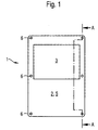
- a device 1 for multimedia presentation has a carrier plate 2 with a window 3 and a cover plate 5.
- the cover plate 5 is arranged on the support plate 2 such that the cover plate 5 completely covers the support plate 2. Further, the cover plate 5 is made of transparent material.
- a static representation which is to be presented by means of the device 1, for example as part of an on-site application of products in a commercial enterprise, may be inserted between the support plate 2 and the cover plate 5.
- the static representation may be, for example, a printed poster whose outer edge coincides with that of the cover plate 5, wherein in the poster a cutout is provided, which is dimensioned and arranged so that the window 3 is not covered by the poster when the poster between the support plate 2 and the cover plate 5 is inserted.
- the poster should be printed on the side facing the cover plate 5, when the poster between the support plate 2 and the cover plate 5 is inserted.
- a moving representation should be arranged directly opposite to the window 3 of the cover plate 5 for this on-site application.
- the moving image is generated by means of a screen which is located on the support plate 2 beyond the cover plate 5, the outer edge of the window 3 substantially coinciding with the outer edge of the image surface of the screen.
- both the poster and the image surface can be viewed by an observer looking at the cover plate 5.
- the viewer takes the moving image shown by the screen simultaneously with the static image shown by the poster, thereby achieving the multimedia character of the presentation of the two representations.
- the poster i. the static representation can always be perceived by the viewer without the need for additional equipment. This is different in the case of the moving display, since the display must be operated accordingly for its display. If the operation of the screen e.g. be temporally interrupted and no image on the image area, i. moving representation, be recognizable, so the viewer is still presented the static representation. It is thereby achieved that even at e.g. an operational failure of the screen of the viewer is still supplied with advertising information on site, namely by means of the static representation.
- both the support plate 2 and the poster and the screen are protected from external influences, such as mechanical influences, such as scratches or shocks, and insensitive to damage and damage.
- the device 1 at the outer edge of the support plate 2 on six bolts 6, which are firmly embedded in the support plate 2.
- six holes are provided to the bolt 6, so that when the cover plate 5 is attached to the support plate, the bolts 6 are in engagement with the associated holes and thereby hold the cover 5 to the support plate 5.
- the bolts 6 and the associated holes are designed such that the bolt-hole connections are detachable and the cover plate is detachable from the support plate manually.
- the cover plate 5 is designed and placed on the support plate 2, that the peripheral edge of the cover plate 5 projects beyond the peripheral edge of the support plate 2 around, so that from the cover plate 5 at its peripheral edge a ring 13 is formed ,
- the rim 13 can be used for manual removal of the cover plate 5 of the support plate 2 under release of the bolt-hole connections as a handle, the collar 13 can be easily engaged behind. Since the ring 13 protrudes from the cover plate 2 and thus does not cover the support plate 2, the course of the peripheral edge of the cover plate 5 does not need to be adapted to the course of the peripheral edge of the support plate 2 and may be designed according to, for example, aesthetic aspects. This offers the possibility to match the external dimensions of the cover plate 5 and thus of the device 1 with the conditions on site and thereby to optimize the external appearance of the device 1.
- the poster is mounted between the support plate 2 and the cover plate 5, it can easily be made accessible, e.g. if the poster is to be replaced or if the poster should be provided with handwritten additions when the cover plate 5 is removed from the support plate 2. Thus, no complicated installation activities are necessary to make the poster available.
- the device 1 has a cuboidal housing 13.
- One of the large sides of the housing 13 is formed by the carrier plate 2.
- the housing 13 is designed such that the screen, a screen supplying data to the player and a screen and the player with Energy supplying power supply unit can be accommodated in the housing.
- This offers the advantage that the device 1 can be operated and operated independently of external technology with regard to the generation of the moving image, whereby a high degree of flexibility is achieved when using the device 1.
- all the necessary apparatuses for generating the moving image (the player, the screen and the power supply unit) are integrable within the housing 13, they are effectively protected against mechanical damage and contamination when installed in the housing 13.
- an LCD monitor is to be used, which has a flat design, so that the housing 13 is also constructed correspondingly flat, whereby the device 1 is space-saving.
- a CF card player is used, to which a CF card 11 is to be supplied for operation.
- the housing 13 is equipped with a slot 4, which is arranged such that the CF card player, the CF card 11 can be supplied from the outside through the slot 4, whereby the handling of the CF card player is facilitated.
- a further embodiment according to the invention has the carrier plate 2, the cover plate 5, the window 3 and the fastening means 6 like the embodiment according to FIGS. 1 to 3.
- the embodiment according to FIG. 4 additionally has two fan elements 14 attached to it as a lateral extension of the carrier plate 2.
- the fan elements 14 each have three superimposed compartments 15, in which, for example, advertised by means of the inventive device 1 goods can be placed. The audience can then take them out of the subjects 15 for closer inspection of these goods and possibly cover again.
- the compartments 15 can also be set up in such a way that a product once taken out of one of the compartments 15 by the audience does not return to this compartment 15 can be returned, so that this product is available to the public directly for sale.
- a base 7 has a column 8 which is provided with two slide rails 9 which are arranged parallel to their longitudinal axis and are arranged at a distance from each other.
- the device 1 is inserted into the slide rails 9, wherein the connection between the device 1 and the slide rails 9 is designed such that the device 1 relative to the column 8 is infinitely adjustable in height.
- the base 7 can be set up as well as independent of the conditions on site, whereby the placement of the device 1 is flexible on site. That is, the stand 7 with the device 1 can be easily transported away from a site and placed on another site, without having to pay attention to mounting options for the device 1.
- stepless height adjustment of the device 1 relative to the column 8 offers the advantage that the arrangement of the device 1 can be adapted to the spatial conditions on site according to, for example, ergonomic or aesthetic aspects.
- a brochure holder 10 is inserted into the slide rails 9. Also this is like the device 1 relative to the column 8 infinitely height adjustable. With the help of the brochure holder 10 prospectuses can be offered to the viewer together with the simultaneous presentation of the static representation and the moving presentation.
Landscapes
- Physics & Mathematics (AREA)
- General Physics & Mathematics (AREA)
- Engineering & Computer Science (AREA)
- Theoretical Computer Science (AREA)
- Devices For Indicating Variable Information By Combining Individual Elements (AREA)
- Overhead Projectors And Projection Screens (AREA)
Abstract
Description
- Die Erfindung betrifft eine Vorrichtung und einen Standfuß zur multimedialen Präsentation, insbesondere eine Vorrichtung zur simultanen Präsentation sowohl einer statischen zweidimensionalen Darstellung als auch einer bewegten zweidimensionalen Darstellung und einen Standfuß zum Halten der Vorrichtung.
- Insbesondere der Einzelhandel, der sich einem immer lebhafter sich entfaltenden Wettbewerb ausgesetzt sieht, baut verstärkt auf die schnelle und umfassende Beratung des Endverbrauchers bzw. des Endanwenders vor Ort über die angebotenen Produkte und Dienstleistungen. Dem Endverbraucher bzw. dem Endanwender, der mit immer vielfältiger werdenden Produktpaletten und Dienstleistungsangeboten zurechtkommen muss, soll hiermit eine Orientierung gegeben werden, damit dieser seine Kaufentscheidung schnell und zielgerichtet treffen kann.
- Ferner ist es in Handelsunternehmen, wie z.B. Spezialgeschäften, Waren-/Kaufhäusern, Fachmärkten oder Supermärkten, übliche Verkaufspraxis, dass zusätzlich zu der Ausstellung von Produkten oder dem Anbieten von Dienstleitungen in Verkaufsräumlichkeiten die ausgestellten Produkte oder die angebotenen Dienstleistungen in den Verkaufsräumlichkeiten beworben werden. Häufig wird das Bewerben der Produkte bzw. der Dienstleistungen so vorgenommen, dass dem Endverbraucher bzw. dem Endanwender die jeweiligen Werbebotschaften in Bild und Ton vor Ort präsentiert werden, wenn der Endverbraucher bzw. der Endanwender in den Verkaufsräumlichkeiten beispielsweise bestimmten Produkten gegenübersteht.
- Insbesondere auf Messen ergibt sich der Bedarf, den Messebesucher interessant, kompakt und eingängig im Rahmen eines Messeauftritts zu informieren. Hierbei ist es erstrebenswert, wenn der Messebesucher bereits beim Besuch eines Messestands Zugang zu allen wichtigen Informationen und Botschaften hat, d.h. ihm alle wichtigen Informationen und Botschaften am Messestand vor Ort präsentiert werden.
- Ferner besteht die Notwendigkeit, insbesondere an öffentlichen Plätzen, die Öffentlichkeit über bestimmte Abläufe, Zusammenhänge, usw. zu informieren, wie beispielsweise die Art und Weise der Bedienung eines Parkautomaten. Schnell und präzise können dabei der Öffentlichkeit Informationen vor Ort präsentiert werden.
- Vor-Ort-Präsentationen sind häufig multimedialer Art, wobei insbesondere statische und/oder bewegte Bilder präsentiert werden, die gegebenenfalls mit statischen und/oder bewegten Schriftzügen kombiniert sind. Ferner wird häufig zusätzlich eine Begleitakustik in Form von Sprache oder Musik eingesetzt, um der jeweiligen Zielgruppe die Information interessant, kompakt und eingängig zu präsentieren.
- Technisch werden multimediale Präsentationssysteme beispielsweise mittels einer Fernsehapparat-Videorecorder-Kombination verwirklicht, die beispielsweise in einem Baumarkt vor einem Regal aufgestellt ist, das mit bestimmten Waren bestückt ist. Dabei wird ein auf einer Videokassette gespeicherter vertonter Kurzfilm mittels des Videorecorders abgespielt und mittels des Fernsehapparats dem interessierten Kunden gezeigt, wobei der Kurzfilm beispielsweise ein Werbespot über diese Waren ist. Zusätzlich ist beispielsweise neben der Fernsehapparat-Videorecorder-Kombination ein Werbeplakat platziert, mittels dessen diese Waren zusätzlich beworben werden.
- Hierbei stellt sich allerdings das Problem, dass der Platzbedarf der verwendeten Gerätschaften groß ist. Ferner ist eine Änderung der zu präsentierenden Information bei beispielsweise Veränderung des Warensortiments oder anderweitigem Einsatz der verwendeten Gerätschaften mit aufwändigen Umbau- und Umrüstmaßnahmen verbunden.
- Aufgabe der Erfindung ist es, eine Vorrichtung zur simultanen Präsentation sowohl von einer statischen zweidimensionalen Darstellung als auch einer bewegten zweidimensionalen Darstellung und einen Standfuß zum Halten der Vorrichtung zu schaffen, wobei der Platzbedarf gering ist und die Verwendung flexibel, unkompliziert und kostengünstig bewerkstelligt werden kann.
- Die erfindungsgemäße Vorrichtung zur simultanen Präsentation einer statischen zweidimensionalen Darstellung und einer bewegten zweidimensionalen Darstellung weist eine Trägerplatte mit einem Fenster und eine abnehmbare durchsichtige Abdeckplatte auf, die die Außenseite der Trägerplatte im Wesentlichen vollständig abdeckt. Die statische Darstellung ist zwischen der Trägerplatte und der Abdeckplatte anbringbar und die bewegte Darstellung ist von außen durch das Fenster sichtbar.
- Die erfindungsgemäße Vorrichtung weist sowohl eine statische als auch eine bewegte zweidimensionale Darstellung auf, die mittels eines aktiven Mediums erzeugbar ist, beispielsweise eines Bildschirms. Dagegen ist die statische Darstellung mittels eines passiven Mediums erzeugbar, beispielsweise eines Aufdrucks, das als solches keinen Betrieb erfordert. Damit wird erreicht, dass grundsätzlich die Präsentation sowohl mittels des passiven als auch des aktiven Mediums bewerkstelligt wird, wobei auch via die statische Darstellung eine Information dem Betrachter vermittelbar ist, selbst wenn die Erzeugung der bewegten Darstellung mittels des aktiven Mediums beispielsweise zeitlich unterbrochen ist.
- Erfindungsgemäß ist die Außenseite der Trägerplatte von der Abdeckplatte im Wesentlichen vollständig abgedeckt, wodurch auch das Fenster von der Abdeckplatte abgedeckt ist. Somit ist sowohl die Trägerplatte als auch die statische und die bewegte Darstellung von Einflüssen von außen geschützt, wie beispielsweise mechanische Einflüsse, wie beispielsweise Kratzer oder Stöße, und unempfindlich gegen Beschädigungen und Beeinträchtigungen.
- Erfindungsgemäß ist die Abdeckplatte im Wesentlichen durchsichtig. Dadurch sind sowohl die statische Darstellung als auch die bewegte Darstellung von außen sichtbar.
- Ferner ist die Abdeckplatte erfindungsgemäß von der Trägerplatte abnehmbar, und die statische Darstellung ist erfindungsgemäß zwischen der Trägerplatte und der Abdeckplatte anbringbar. Somit ist grundsätzlich die statische Darstellung von außen zugänglich, wenn die Abdeckplatte von der Trägerplatte abgenommen ist. Dadurch wird erreicht, dass zum Verändern oder Austauschen der statischen Darstellung vor Ort, zum Beispiel beim Wechseln der zu übermittelnden Information, die statische Darstellung leicht zugänglich gemacht werden kann, wenn die Abdeckplatte von der Trägerplatte abgenommen wird, wodurch ein zeitaufwändiges und kostenintensives Demontieren der erfindungsgemäßen Vorrichtung von dem Aufstellungsort, Verändern oder Austauschen der statischen Darstellung an einem anderen Ort als dem Aufstellungsort und wieder Montieren der erfindungsgemäßen Vorrichtung an dem Aufstellungsort entfallen kann. Vielmehr kann ein Verändern oder Austauschen der statischen Darstellung vor Ort vorgenommen werden.
- Die Abdeckplatte kann beispielsweise an der Trägerplatte festgeklebt sein. Bevorzugt ist die Abdeckplatte mittels eines lösbaren Befestigungsmittels an der Trägerplatte befestigt, so dass die Abdeckplatte bequem ohne den Einsatz zusätzlicher Materialien und/oder Werkzeugen vor Ort abnehmbar und wieder anbringbar ist.
- Der Umfangsrand der Abdeckplatte kann beispielsweise mit dem Umfangsrand der Trägerplatte bündig verlaufen, wenn die Abdeckplatte an der Trägerplatte angebracht ist. Bevorzugt ist der Umfangsrand der Abdeckplatte so gestaltet, dass er über den Umfangsrand der Trägerplatte vorsteht, so dass die Abdeckplatte zum Ablösen von der Trägerplatte bequem an deren Umfangsrand hintergriffen werden kann.
- Außerdem kann die Abdeckplatte im Wesentlichen die Flächenform der Trägerplatte haben, beispielsweise kann die Abdeckplatte rechteckig sein, wenn die Trägerplatte ebenfalls rechteckig ist. Bevorzugt ist, dass die Abdeckplatte eine an die Gegebenheiten vor Ort angepasste oder nach gestalterischen Gesichtspunkten geformte vorbestimmte Flächenform hat, beispielsweise rund, die von der Flächenform der Trägerplatte unabhängig ist, die beispielsweise rechteckig ist.
- Die statische Darstellung kann beispielsweise ein Aufdruck sein, der auf der Trägerplatte angebracht ist. Bevorzugt ist die statische Darstellung ein Poster, der zwischen der Trägerplatte und der Abdeckplatte einlegbar ist. Somit kann eine Veränderung oder ein Austauschen der statischen Darstellung vor Ort durch Abnehmen der Abdeckplatte von der Trägerplatte, Herausnehmen des bereits installierten Posters, Einlegen eines neuen Posters und wieder Anbringen der Abdeckplatte an der Trägerplatte bewerkstelligt werden. Dies bietet den Vorteil, dass eine Veränderung oder ein Austauschen der statischen Darstellung vor Ort schnell durchführbar ist, da keine aufwändigen Montagetätigkeiten notwendig sind. Ferner ist der Materialaufwand und somit die Kosten gering, da lediglich der Poster ausgetauscht wird, der üblich aus einem billigen Material hergestellt ist, wie beispielsweise Papier oder einer Kunststofffolie. In diesem Sinne ebenso vorteilhaft ist die statische Darstellung eine Platte beispielsweise aus Glas oder Kunststoff.
- Alternativ ist die statische Darstellung auf der Abdeckplatte in der Art eines Aufdrucks vorgesehen. Hierbei braucht bei einer Veränderung oder einem Austauschen der statischen Darstellung vor Ort lediglich die Abdeckplatte ausgetauscht zu werden, woraus sich im Prinzip ebenfalls die oben beschriebenen Vorteile ergeben.
- Die Abdeckplatte kann beispielsweise eine Glasscheibe sein. Bevorzugt ist jedoch die Abdeckplatte eine Acrylglasscheibe. Eine Acrylglasscheibe bietet den Vorteil, dass sie günstig in der Anschaffung und leicht bearbeitbar ist.
- Die bewegte Darstellung wird bevorzugt von einer Erzeugungseinheit erzeugt, die ein Abspielgerät, einen Bildschirm und eine Energieversorgungseinheit aufweist. Die Erzeugungseinheit kann beispielsweise teilweise oder vollständig außerhalb der Vorrichtung untergebracht sein. Bevorzugt ist allerdings, dass die Erzeugungseinheit in die Vorrichtung vollständig integrierbar ist. Dies ist vorteilhaft, da die erfindungsgemäße Vorrichtung mit vollständig integrierter Erzeugungseinheit unabhängig von externer Technik, wie beispielsweise einem PC, montierbar, bedienbar und betreibbar ist, wodurch eine hohe Flexibilität beim Einsatz der erfindungsgemäßen Vorrichtung erreicht wird.
- Die Vorrichtung kann beispielsweise mehrere Trägerstreben aufweisen, an denen das Abspielgerät, der Bildschirm und die Energieversorgungseinheit der Erzeugungseinheit befestigt sind. Allerdings weist bevorzugt die Vorrichtung ein Gehäuse auf, in dem die Erzeugungseinheit unterbringbar ist. Dadurch wird vorteilhaft erreicht, dass die Komponenten der Erzeugungseinheit (das Abspielgerät, der Bildschirm und die Energieversorgungseinheit) nach außen geschützt sind und unempfindlich gegen Beschädigung und Verschmutzung sind.
- Der Bildschirm kann eine Braun'sche Röhre aufweisen. Bevorzugt ist der Bildschirm ein LCD-Monitor oder ein OLED-Monitor mit/ohne Touch-Screen-Funktion. Dies bietet den Vorteil, dass die Vorrichtung eine flache Bauweise aufweist, die platzsparend und leicht ist. Ferner ist die Bildqualität des LCD-Monitors und des OLED-Monitors gut, d.h., das Bild ist flimmerfrei, an jeder Stelle des LCD-Monitors und des OLED-Monitors gleich scharf, entspiegelt und nicht verzerrt, wobei der LCD-Monitor und der OLED-Monitor eine hohe Leuchtkraft und gute Kontrasteigenschaften sowie einen geringen Stromverbrauch aufweiset. Ferner ist der LCD-Monitor und der OLED-Monitor vorteilhaft strahlungsarm und umweltfreundlich.
- Das Abspielgerät kann ein Video-Abspielgerät sein. Bevorzugt ist das Abspielgerät ein CF-Card-Abspielgerät, ein DVD-Abspielgerät, ein Bluray-Abspielgerät, ein HD-DVD-Abspielgerät oder ein Personal Computer, wobei das Abspielgerät bevorzugt eine Speicherkarte oder eine Festplatte aufweist. Dies bietet den Vorteil, dass einerseits platzsparende digitale Speichermedien mit hoher Speicherdichte einsetzbar sind, wie beispielsweise eine CF-Card oder eine DVD. Hierbei können Dateien verwendet werden, die ein gängiges Dateiformat haben, wie beispielsweise DVD, MPEG, MP3, JPG oder jedes andere bekannte Bilddatei- oder Videodateiformat, wobei die Dateien mit gängiger Software und Hardware leicht erzeugbar und veränderbar sind.
- Ferner weist bevorzugt das Abspielgerät einen Lautsprecher auf, mit dem eine akustische Präsentation möglich ist.
- Die Vorrichtung kann beispielsweise eine Öffnung aufweisen, die mit einem verschwenkbaren Deckel verschließbar ist, durch die eine CF-Card oder eine DVD dem Abspielgerät zuführbar ist. Bevorzugt ist allerdings ein Schlitz in der Vorrichtung vorgesehen, durch den die CF-Card oder die DVD dem Abspielgerät zugeführt werden kann. Dies ist vorteilhaft, da durch einfache Handhabung das Abspielgerät mit Speichermedien bestückbar ist, wodurch die Bedienung des Abspielgeräts erleichtert ist.
- Bevorzugt ist das Abspielgerät zusätzlich mit einem internetgestützten kabellosen Dateneinspeisungssystem ausgestattet, wodurch das Abspielgerät vorteilhaft von der Ferne via das Internet bedient werden kann. Bevorzugt basiert das Dateneinspeisungssystem auf LAN, WLAN, WAN, PAN, USB, Wireless USB, IRDA oder Bluetooth. Ferner können die Abspielgeräte, die in mehreren, parallel betriebenen Vorrichtungen eingebaut sind, gleichzeitig angesteuert werden.
- Die Energieversorgungseinheit ist bevorzugt ein Netzteil mit einem externen Netzkabel, das an ein Stromnetz anschließbar ist, oder eine Batterieeinheit.
- Außerdem ist bevorzugt an der Vorrichtung eine Kamera, eine Auswahleinrichtung zur Manipulation der bewegten Darstellung, beispielsweise ein Schalter, oder ein Bewegungsmelder anbringbar.
- Ferner ist die Vorrichtung bevorzugt mit einem Mittel zum Einlagern von Waren versehen. Dieses Mittel kann beispielsweise eine Mehrzahl von Fächern sein, in die Waren hineingelegt werden können, die mittels der Vorrichtung beworben werden, und aus denen diese Waren vom Publikum wieder herausgenommen werden können, beispielsweise, um diese Waren genau zu betrachten oder zu kaufen.
- Der erfindungsgemäße Standfuß weist eine Säule und die erfindungsgemäße Vorrichtung auf, wobei die erfindungsgemäße Vorrichtung an der Säule angebracht ist.
- Da der erfindungsgemäße Standfuß so gut wie unabhängig von den Gegebenheiten vor Ort aufstellbar ist, kann der Standfuß einfach von einem Aufstellungsort wegtransportiert und an einen anderen Aufstellungsort gestellt werden, wodurch erreicht wird, dass die Vorrichtung unabhängig von den Gegebenheiten am Aufstellungsort angebracht werden kann.
- Beispielsweise kann die Vorrichtung an der Säule fest angebracht sein. Bevorzugt ist, dass die Vorrichtung relativ zur Säule höhenverstellbar ist. Dies ist vorteilhaft, da somit die Anordnung der Vorrichtung an die räumlichen Verhältnisse vor Ort nach beispielsweise ergonomischen oder ästhetischen Gesichtspunkten angepasst werden kann.
- Bevorzugt weist der Standfuß mindestens eine Gleitschiene auf, die im Wesentlichen parallel zur Längsachse der Säule verläuft, wobei die Vorrichtung verschiebbar in die Gleitschiene eingesetzt ist. Dies bietet den Vorteil, dass die Vorrichtung stufenlos entlang der Gleitschiene platziert werden kann, woraus sich eine hohe Flexibilität bei der Anordnung der Vorrichtung ergibt.
- Außerdem können bevorzugt weitere Accessoires, insbesondere Prospekthalter, in die Gleitschiene verschiebbar eingesetzt werden. Dies ist vorteilhaft, da dem Betrachter zusätzliche Informationsträger, insbesondere Prospekte, zusammen mit der simultanen Präsentation der statischen Darstellung und der bewegen Darstellung angeboten werden können.
- Im Folgenden wird die Erfindung anhand einer bevorzugten Ausführungsform mit Bezugnahme auf die Zeichnung erläutert. In der Zeichnung zeigen
- Figur 1 eine Draufsicht einer ersten Ausführungsform der erfindungsgemäßen Vorrichtung,
- Figur 2 eine Schnittdarstellung der ersten Ausführungsform entlang der Linie A-A in Figur 1,
- Figur 3 eine Seitenansicht der ersten Ausführungsform,
- Figur 4 eine Draufsicht einer zweiten Ausführungsform der erfindungsgemäßen Vorrichtung,
- Figur 5 eine Vorderansicht eines erfindungsgemäßen Standfußes mit der Vorrichtung und einem Prospekthalter und
- Figur 6 eine Seitenansicht des Standfußes aus Figur 5.
- Wie aus Figuren 1 und 2 ersichtlich ist, weist eine Vorrichtung 1 zur multimedialen Präsentation eine Trägerplatte 2 mit einem Fenster 3 und eine Abdeckplatte 5 auf. Die Abdeckplatte 5 ist derart auf der Trägerplatte 2 angeordnet, dass die Abdeckplatte 5 die Trägerplatte 2 vollständig abdeckt. Ferner ist die Abdeckplatte 5 aus durchsichtigem Material.
- Eine statische Darstellung, die mit Hilfe der Vorrichtung 1 präsentiert werden soll, zum Beispiel im Rahmen einer Vor-Ort-Bewerbung von Produkten in einem Handelsunternehmen, kann zwischen der Trägerplatte 2 und der Abdeckplatte 5 eingelegt sein. Die statische Darstellung kann beispielsweise ein bedruckter Poster sein, dessen Außenrand mit dem der Abdeckplatte 5 übereinstimmt, wobei in dem Poster ein Ausschnitt vorgesehen ist, der derart dimensioniert und angeordnet ist, dass das Fenster 3 nicht von dem Poster abgedeckt wird, wenn der Poster zwischen der Trägerplatte 2 und der Abdeckplatte 5 eingelegt ist. Der Poster soll auf derjenigen Seite bedruckt sein, die der Abdeckplatte 5 zugewandt ist, wenn der Poster zwischen der Trägerplatte 2 und der Abdeckplatte 5 eingelegt ist.
- Außerdem soll für diese Vor-Ort-Bewerbung eine bewegte Darstellung unmittelbar an dem Fenster 3 der Abdeckplatte 5 gegenüberliegend angeordnet sein. Üblicherweise wird die bewegte Darstellung mittels eines Bildschirms erzeugt, der jenseits der Abdeckplatte 5 an der Trägerplatte 2 angesiedelt, wobei der Außenrand des Fensters 3 im Wesentlichen mit dem Außenrand der Bildfläche des Bildschirms zusammenfällt.
- Da die Abdeckplatte 5 durchsichtig ist, kann sowohl der Poster als auch die Bildfläche von einem Beobachter betrachtet werden, der auf die Abdeckplatte 5 blickt. Dadurch, dass die Bildfläche an dem Fenster 3 angeordnet ist, nimmt der Betrachter die von dem Bildschirm gezeigte bewegte Darstellung gleichzeitig mit der von dem Poster gezeigte statischen Darstellung war, wodurch der multimediale Charakter der Präsentation der beiden Darstellungen erzielt wird.
- Der Poster, d.h. die statische Darstellung, kann von dem Betrachter stets wahrgenommen werden, ohne dass hierfür zusätzliche Gerätschaften notwendig sind. Anders ist dies bei der bewegten Darstellung, da für ihr Zeigen der Bildschirm entsprechend betrieben werden muss. Sollte der Betrieb des Bildschirms z.B. zeitlich unterbrochen sein und an der Bildfläche kein Bild, d.h. bewegte Darstellung, erkennbar sein, so wird dem Betrachter dennoch die statische Darstellung entgegengebracht. Dadurch wird erreicht, dass selbst bei z.B. einem Betriebsausfall des Bildschirms der Betrachter dennoch mit Werbeinformation vor Ort versorgt wird, nämlich mittels der statischen Darstellung.
- Die Außenseite der Trägerplatte 2 und dessen Fenster 3 sind von der Abdeckplatte 5 abgedeckt. Somit sind sowohl die Trägerplatte 2 als auch der Poster und der Bildschirm von Einflüssen von außen geschützt, wie beispielsweise mechanische Einflüsse, wie beispielsweise Kratzer oder Stöße, und unempfindlich gegen Beschädigungen und Beeinträchtigungen.
- Wie ferner aus Figuren 1 und 2 ersichtlich ist, weist die Vorrichtung 1 am Außenrand der Trägerplatte 2 sechs Bolzen 6 auf, die in die Trägerplatte 2 fest eingelassen sind. An den entsprechenden Stellen der Trägerplatte 5 sind zu den Bolzen 6 sechs Löcher vorgesehen, so dass, wenn die Abdeckplatte 5 an der Trägerplatte angebracht ist, die Bolzen 6 mit den dazugehörigen Löchern in Eingriff stehen und dadurch die Abdeckplatte 5 an der Trägerplatte 5 halten. Die Bolzen 6 und die dazugehörigen Löcher sind derart ausgestaltet, dass die Bolzen-Löcher-Verbindungen lösbar sind und die Abdeckplatte von der Trägerplatte händisch abnehmbar ist.
- Wie aus Figur 2 ersichtlich ist, ist die Abdeckplatte 5 derart gestaltet und derart an der Trägerplatte 2 platziert, dass der Umfangsrand der Abdeckplatte 5 über den Umfangsrand der Trägerplatte 2 ringsum vorsteht, so dass von der Abdeckplatte 5 an deren Umfangsrand ein Kranz 13 gebildet ist. Der Kranz 13 kann zum händischen Abnehmen der Abdeckplatte 5 von der Trägerplatte 2 unter Lösen der Bolzen-Löcher-Verbindungen als Griff benutzt werden, wobei der Kranz 13 bequem hintergriffen werden kann. Da der Kranz 13 von der Abdeckplatte 2 vorsteht und somit nicht die Trägerplatte 2 abdeckt, braucht der Verlauf des Umfangsrands der Abdeckplatte 5 nicht an den Verlauf des Umfangsrands der Trägerplatte 2 angepasst zu sein und kann nach beispielsweise ästhetischen Gesichtspunkten gestaltet sein. Dies bietet die Möglichkeit die Außenabmaße der Abdeckplatte 5 und somit der Vorrichtung 1 mit den Verhältnissen vor Ort abzustimmen und dadurch auf das äußere Erscheinungsbild der Vorrichtung 1 zu optimieren.
- Ist der Poster zwischen der Trägerplatte 2 und der Abdeckplatte 5 angebracht, so kann dieser einfach zugänglich gemacht werden, z.B. wenn der Poster ausgetauscht werden soll oder wenn der Poster mit handschriftlichen Ergänzungen versehen werden sollen, wenn die Abdeckplatte 5 von der Trägerplatte 2 abgenommen wird. Somit sind zur Zugänglichmachung des Posters keine aufwändigen Montagetätigkeiten notwendig.
- Wie aus Figuren 2 und 3 ersichtlich ist, weist die Vorrichtung 1 ein quaderförmiges Gehäuse 13 auf. Eine der großen Seiten des Gehäuses 13 wird von der Trägerplatte 2 gebildet. Das Gehäuse 13 ist derart gestaltet, dass der Bildschirm, ein den Bildschirm mit Daten versorgendes Abspielgerät und eine den Bildschirm und das Abspielgerät mit Energie versorgende Energieversorgungseinheit in dem Gehäuse untergebracht werden können. Dies bietet den Vorteil, dass die Vorrichtung 1 hinsichtlich der Erzeugung der bewegten Darstellung unabhängig von externer Technik bedienbar und betreibbar ist, wodurch eine hohe Flexibilität beim Einsatz der Vorrichtung 1 erreicht wird. Ferner, da alle notwendigen Gerätschaften zur Erzeugung der bewegten Darstellung (das Abspielgerät, der Bildschirm und die Energieversorgungseinheit) innerhalb des Gehäuses 13 integrierbar sind, sind sie effektiv gegen mechanische Beschädigung und Verschmutzung geschützt, wenn sie in das Gehäuse 13 eingebaut sind.
- Für den Bildschirm ist ein LCD-Monitor zu verwenden, der eine flache Bauweise hat, so dass das Gehäuse 13 ebenfalls entsprechend flach gebaut ist, wodurch die Vorrichtung 1 platzsparend ist.
- Für das Abspielgerät ist ein CF-Card-Abspielgerät zu verwenden, dem zum Betreiben eine CF-Card 11 zuzuführen ist. Hierfür ist das Gehäuse 13 mit einem Schlitz 4 ausgestattet, der derart angeordnet ist, dass dem CF-Card-Abspielgerät die CF-Card 11 von außen durch den Schlitz 4 zugeführt werden kann, wodurch die Handhabung des CF-Card-Abspielgeräts erleichtert ist.
- Wie es aus Figur 4 ersichtlich ist, weist eine weitere erfindungsgemäße Ausführungsform die Trägerplatte 2, die Abdeckplatte 5, das Fenster 3 und die Befestigungsmittel 6 wie die Ausführungsform gemäß den Figuren 1 bis 3 auf. Die Ausführungsform gemäß Figur 4 weist jedoch zusätzlich jeweils als seitliche Verlängerung der Trägerplatte 2 an dieser angebracht zwei Fächerelemente 14 auf. Die Fächerelemente 14 weisen jeweils drei übereinanderliegend angeordnete Fächer 15 auf, in die beispielsweise mittels der erfindungsgemäßen Vorrichtung 1 beworbene Waren hineingelegt werden können. Das Publikum kann dann zur näheren Inspektion dieser Waren diese aus den Fächern 15 herausnehmen und gegebenenfalls wieder zurücklegen. Die Fächer 15 können auch derart eingerichtet sein, dass eine von dem Publikum erst einmal aus einem der Fächer 15 herausgenommene Ware nicht wieder in dieses Fach 15 zurückbringbar ist, so dass diese Ware dem Publikum direkt zum Kauf zur Verfügung steht.
- Wie es aus Figuren 5 und 6 ersichtlich ist, weist ein Standfuß 7 eine Säule 8 auf, die mit zwei zu ihrer Längsachse parallel verlaufende im Abstand voneinander angeordnete Gleitschienen 9 versehen ist. Die Vorrichtung 1 ist in die Gleitschienen 9 eingesetzt, wobei die Verbindung zwischen der Vorrichtung 1 und der Gleitschienen 9 derart gestaltet ist, dass die Vorrichtung 1 relativ zur Säule 8 stufenlos höhenverstellbar ist.
- Der Standfuß 7 kann so gut wie unabhängig von den Gegebenheiten vor Ort aufgestellt werden, wodurch die Platzierung der Vorrichtung 1 vor Ort flexibel ist. D.h., der Standfuß 7 mit der Vorrichtung 1 kann einfach von einem Aufstellungsort wegtransportiert und an einem anderen Aufstellungsort aufgestellt werden, ohne dabei auf Montagemöglichkeiten für die Vorrichtung 1 achten zu müssen.
- Außerdem bietet die stufenlose Höhenverstellbarkeit der Vorrichtung 1 relativ zur Säule 8 den Vorteil, dass die Anordnung der Vorrichtung 1 an die räumlichen Verhältnisse vor Ort nach beispielsweise ergonomischen oder ästhetischen Gesichtspunkten angepasst werden kann.
- Wie ferner aus Figuren 5 und 6 ersichtlich ist, ist in die Gleitschienen 9 ein Prospekthalter 10 eingesetzt. Auch dieser ist wie die Vorrichtung 1 relativ zur Säule 8 stufenlos höhenverstellbar. Mit Hilfe des Prospekthalters 10 können dem Betrachter Prospekte zusammen mit der simultanen Präsentation der statischen Darstellung und der bewegen Darstellung angeboten werden.
Claims (20)
- Vorrichtung (1) zur simultanen Präsentation einer statischen zweidimensionalen Darstellung und einer bewegten zweidimensionalen Darstellung, aufweisend eine Trägerplatte (2) mit einem Fenster (3) und einer abnehmbaren im Wesentlichen durchsichtigen Abdeckplatte (5), die die Außenseite der Trägerplatte (2) im Wesentlichen vollständig abdeckt, wobei die statische Darstellung zwischen der Trägerplatte (2) und der Abdeckplatte (5) anbringbar ist und die bewegte Darstellung von außen durch das Fenster (3) sichtbar ist.
- Vorrichtung (1) gemäß Anspruch 1, wobei die Abdeckplatte (5) mittels lösbaren Befestigungsmitteln (6) an der Trägerplatte (2) festgelegt ist.
- Vorrichtung (1) gemäß Anspruch 1 oder 2, wobei die Abdeckplatte (5) über den Umfangsrand der Trägerplatte (2) vorsteht.
- Vorrichtung (1) gemäß Anspruch 3, wobei die Abdeckplatte (5) eine vorbestimmte Flächenform hat, die von der Fächenform der Trägerplatte (2) unabhängig ist.
- Vorrichtung (1) gemäß einem der vorhergehenden Ansprüche, wobei die statische Darstellung ein Poster vorzugsweise aus Papier oder einer Kunststofffolie, der zwischen der Trägerplatte (2) und der Abdeckplatte (5) einlegbar ist, oder eine Platte vorzugsweise aus Glas oder Kunststoff ist, die zwischen der Trägerplatte (2) und der Abdeckplatte (5) einlegbar ist, oder ein Aufdruck auf der Abdeckplatte (5) ist.
- Vorrichtung (1) gemäß einem der vorhergehenden Ansprüche, wobei die Abdeckplatte (5) eine Acrylglasscheibe ist.
- Vorrichtung (1) gemäß einem der vorhergehenden Ansprüche, wobei die bewegte Darstellung von einer Erzeugungseinheit erzeugbar ist, die ein Abspielgerät, einen Bildschirm und eine Energieversorgungseinheit aufweist, wobei die Erzeugungseinheit in die Vorrichtung (1) vollständig integrierbar ist.
- Vorrichtung (1) gemäß Anspruch 7, wobei die Vorrichtung (1) ein Gehäuse (12) aufweist, in dem die Erzeugungseinheit unterbringbar ist.
- Vorrichtung (1) gemäß Anspruch 7 oder 8, wobei der Bildschirm ein LCD-Monitor mit/ohne Touch-Screen-Funktion oder ein OLED-Monitor ohne/mit Touch-Screen-Funktion ist.
- Vorrichtung (1) gemäß einem der Ansprüche 7 bis 9, wobei das Abspielgerät ein CF-Card-Abspielgerät, ein DVD-Abspielgerät, ein Bluray-Abspielgerät, ein HD-DVD-Abspielgerät oder ein Personal Computer ist, wobei das Abspielgerät bevorzugt eine Speicherkarte oder eine Festplatte aufweist.
- Vorrichtung (1) gemäß einem der Ansprüche 7 bis 10, wobei das Abspielgerät einen Lautsprecher aufweist.
- Vorrichtung (1) gemäß Anspruch 10 oder 11, wobei die Vorrichtung (1) einen Schlitz (4) aufweist, durch den eine CF-Card oder eine DVD dem Abspielgerät zuführbar ist.
- Vorrichtung (1) gemäß einem der Ansprüche 7 bis 12, wobei das Abspielgerät ein internetgestütztes kabelloses Dateneinspeisungssystem aufweist, das bevorzugt auf LAN, WLAN, WAN, PAN, USB, Wireless USB, IRDA oder Bluetooth basiert.
- Vorrichtung (1) gemäß einem der Ansprüche 7 bis 13, wobei die Energieversorgungseinheit ein Netzteil mit einem externen Netzkabel oder eine Batterieeinheit ist.
- Vorrichtung (1) gemäß einem der vorhergehenden Ansprüche, wobei an der Vorrichtung (1) eine Kamera, eine Auswahleinrichtung zur Manipulation der bewegten Darstellung oder ein Bewegungsmelder anbringbar ist.
- Vorrichtung (1) gemäß einem der vorhergehenden Ansprüche, wobei die Vorrichtung (1) mit einem Mittel zum Einlagern von Waren, insbesondere Fächern, versehen ist.
- Standfuß mit einer Säule (8) und der Vorrichtung (1) gemäß einem der vorhergehenden Ansprüche, wobei die Vorrichtung (1) an der Säule (8) angebracht ist.
- Standfuß (7) gemäß Anspruch 17, wobei die Vorrichtung (1) relativ zu der Säule (8) höhenverstellbar ist.
- Standfuß (7) gemäß Anspruch 17 oder 18, wobei die Säule (8) eine im wesentlichen parallel zur Längsachse der Säule sich erstreckende Gleitschiene (9) aufweist, in die die Vorrichtung (1) verschiebbar eingesetzt ist.
- Standfuß (7) gemäß Anspruch 19, wobei Accessoires, insbesondere ein Prospekthalter (10), in die Gleitschiene (9) verschiebbar einsetzbar ist.
Applications Claiming Priority (1)
| Application Number | Priority Date | Filing Date | Title |
|---|---|---|---|
| DE200520007175 DE202005007175U1 (de) | 2005-05-04 | 2005-05-04 | Vorrichtung und Standfuß zur multimedialen Präsentation |
Publications (3)
| Publication Number | Publication Date |
|---|---|
| EP1720147A2 true EP1720147A2 (de) | 2006-11-08 |
| EP1720147A3 EP1720147A3 (de) | 2007-09-05 |
| EP1720147B1 EP1720147B1 (de) | 2011-06-15 |
Family
ID=34877914
Family Applications (1)
| Application Number | Title | Priority Date | Filing Date |
|---|---|---|---|
| EP06006568A Expired - Lifetime EP1720147B1 (de) | 2005-05-04 | 2006-03-29 | Vorrichtung und Standfuß zur multimedialen Präsentation |
Country Status (3)
| Country | Link |
|---|---|
| EP (1) | EP1720147B1 (de) |
| AT (1) | ATE513289T1 (de) |
| DE (1) | DE202005007175U1 (de) |
Cited By (1)
| Publication number | Priority date | Publication date | Assignee | Title |
|---|---|---|---|---|
| EP2425743A1 (de) | 2010-09-07 | 2012-03-07 | Wanzl Metallwarenfabrik Gmbh | Ausgabegerät |
Citations (2)
| Publication number | Priority date | Publication date | Assignee | Title |
|---|---|---|---|---|
| US20030056411A1 (en) | 2001-07-11 | 2003-03-27 | Jos Wijtenburg | Interactive showcase and display wall |
| US20040233220A1 (en) | 2003-05-21 | 2004-11-25 | Jean-Francois Decaux | Display device |
Family Cites Families (2)
| Publication number | Priority date | Publication date | Assignee | Title |
|---|---|---|---|---|
| DE29702104U1 (de) * | 1997-02-07 | 1997-04-24 | Loewe Opta GmbH, 96317 Kronach | Bildschirmgerät |
| US6384736B1 (en) * | 1998-04-30 | 2002-05-07 | Dave Gothard | Remote control electronic display system |
-
2005
- 2005-05-04 DE DE200520007175 patent/DE202005007175U1/de not_active Expired - Lifetime
-
2006
- 2006-03-29 EP EP06006568A patent/EP1720147B1/de not_active Expired - Lifetime
- 2006-03-29 AT AT06006568T patent/ATE513289T1/de active
Patent Citations (2)
| Publication number | Priority date | Publication date | Assignee | Title |
|---|---|---|---|---|
| US20030056411A1 (en) | 2001-07-11 | 2003-03-27 | Jos Wijtenburg | Interactive showcase and display wall |
| US20040233220A1 (en) | 2003-05-21 | 2004-11-25 | Jean-Francois Decaux | Display device |
Cited By (3)
| Publication number | Priority date | Publication date | Assignee | Title |
|---|---|---|---|---|
| EP2425743A1 (de) | 2010-09-07 | 2012-03-07 | Wanzl Metallwarenfabrik Gmbh | Ausgabegerät |
| DE102010044609A1 (de) | 2010-09-07 | 2012-03-08 | Wanzl Metallwarenfabrik Gmbh | Ausgabegerät |
| DE102010044609B4 (de) * | 2010-09-07 | 2012-12-06 | Wanzl Metallwarenfabrik Gmbh | Ausgabegerät für das Anordnen von Informations- und/oder Werbebroschüren |
Also Published As
| Publication number | Publication date |
|---|---|
| ATE513289T1 (de) | 2011-07-15 |
| DE202005007175U1 (de) | 2005-08-18 |
| EP1720147B1 (de) | 2011-06-15 |
| EP1720147A3 (de) | 2007-09-05 |
Similar Documents
| Publication | Publication Date | Title |
|---|---|---|
| EP1168285B1 (de) | Spiegel mit einem als Informationsgeber ausgebildeten Teilbereich | |
| DE10101104A1 (de) | Flachbildschirm mit austauschbarem Gerätefuß | |
| DE29811821U1 (de) | Audiovisuelles Informationssystem | |
| EP1276092B1 (de) | Interaktiver Schaukasten und Schauwand | |
| DE19726413A1 (de) | Multimediales Präsentationsgerät | |
| EP1429308B1 (de) | Elektronisch ansteuerbares Display | |
| EP1720147B1 (de) | Vorrichtung und Standfuß zur multimedialen Präsentation | |
| DE69405744T2 (de) | Einzelhandelsanzeigevorrichtung | |
| DE60313555T2 (de) | System zur Präsentation von Bildaufnahmegeräten,wie Standbildkameras und Videokameras | |
| DE10139890B4 (de) | Spiegel mit einem als Imformationsgeber ausgebildeten Teilbereich | |
| DE212010000105U1 (de) | Demontierbares und tragbares System zur digitalen, grafischen Anzeige | |
| EP1349474A1 (de) | Multimedia-ladenbauregal | |
| EP1626387A1 (de) | Präsentationssystem für Schaufenster | |
| DE20113823U1 (de) | Servicestation | |
| DE202008017186U1 (de) | Werbedisplay | |
| DE29821588U1 (de) | Tischmöbel für PC-unterstützte Beratungen und Konferenzen | |
| DE19958860A1 (de) | Präsentationseinrichtung für Bewegtbilder | |
| EP1189189A1 (de) | Anordnung zur Darstellung von Bildern und Regalboden | |
| DE202006019429U1 (de) | Vorrichtung zur Präsentation von Produkten | |
| DE202008014189U1 (de) | Vitrine | |
| DE29509604U1 (de) | Einrichtung zur Versorgung von Passanten mit Hörbotschaften | |
| EP0860737A1 (de) | Bildwiedergabeeinrichtung | |
| DE202024106022U1 (de) | Verkaufseinrichtung für Glücksspielscheine | |
| DE29601901U1 (de) | Einrichtung zur Versorgung von Personen mit Hör- und Bildbotschaften | |
| DE202005013438U1 (de) | Werbe-Displayvorrichtung |
Legal Events
| Date | Code | Title | Description |
|---|---|---|---|
| PUAI | Public reference made under article 153(3) epc to a published international application that has entered the european phase |
Free format text: ORIGINAL CODE: 0009012 |
|
| AK | Designated contracting states |
Kind code of ref document: A2 Designated state(s): AT BE BG CH CY CZ DE DK EE ES FI FR GB GR HU IE IS IT LI LT LU LV MC NL PL PT RO SE SI SK TR |
|
| AX | Request for extension of the european patent |
Extension state: AL BA HR MK YU |
|
| PUAL | Search report despatched |
Free format text: ORIGINAL CODE: 0009013 |
|
| RIC1 | Information provided on ipc code assigned before grant |
Ipc: G09F 15/00 20060101ALI20070719BHEP Ipc: G09F 27/00 20060101AFI20060830BHEP Ipc: G09F 9/35 20060101ALI20070719BHEP |
|
| AK | Designated contracting states |
Kind code of ref document: A3 Designated state(s): AT BE BG CH CY CZ DE DK EE ES FI FR GB GR HU IE IS IT LI LT LU LV MC NL PL PT RO SE SI SK TR |
|
| AX | Request for extension of the european patent |
Extension state: AL BA HR MK YU |
|
| 17P | Request for examination filed |
Effective date: 20080305 |
|
| AKX | Designation fees paid |
Designated state(s): AT BE BG CH CY CZ DE DK EE ES FI FR GB GR HU IE IS IT LI LT LU LV MC NL PL PT RO SE SI SK TR |
|
| 17Q | First examination report despatched |
Effective date: 20080418 |
|
| R17C | First examination report despatched (corrected) |
Effective date: 20090227 |
|
| GRAP | Despatch of communication of intention to grant a patent |
Free format text: ORIGINAL CODE: EPIDOSNIGR1 |
|
| RIC1 | Information provided on ipc code assigned before grant |
Ipc: G09F 27/00 20060101AFI20110309BHEP Ipc: G09F 15/00 20060101ALI20110309BHEP |
|
| GRAS | Grant fee paid |
Free format text: ORIGINAL CODE: EPIDOSNIGR3 |
|
| GRAA | (expected) grant |
Free format text: ORIGINAL CODE: 0009210 |
|
| AK | Designated contracting states |
Kind code of ref document: B1 Designated state(s): AT BE BG CH CY CZ DE DK EE ES FI FR GB GR HU IE IS IT LI LT LU LV MC NL PL PT RO SE SI SK TR |
|
| REG | Reference to a national code |
Ref country code: GB Ref legal event code: FG4D Free format text: NOT ENGLISH Ref country code: CH Ref legal event code: EP |
|
| REG | Reference to a national code |
Ref country code: CH Ref legal event code: NV Representative=s name: RIEDERER HASLER & PARTNER PATENTANWAELTE AG Ref country code: CH Ref legal event code: PCOW Free format text: LOTHAR RECHT;ELISABETH-KUEHLING-WEG 42;48653 COESFELD (DE) |
|
| REG | Reference to a national code |
Ref country code: IE Ref legal event code: FG4D Free format text: LANGUAGE OF EP DOCUMENT: GERMAN |
|
| REG | Reference to a national code |
Ref country code: DE Ref legal event code: R096 Ref document number: 502006009642 Country of ref document: DE Effective date: 20110728 |
|
| REG | Reference to a national code |
Ref country code: FR Ref legal event code: CA Effective date: 20110829 |
|
| REG | Reference to a national code |
Ref country code: NL Ref legal event code: VDEP Effective date: 20110615 |
|
| PG25 | Lapsed in a contracting state [announced via postgrant information from national office to epo] |
Ref country code: LT Free format text: LAPSE BECAUSE OF FAILURE TO SUBMIT A TRANSLATION OF THE DESCRIPTION OR TO PAY THE FEE WITHIN THE PRESCRIBED TIME-LIMIT Effective date: 20110615 Ref country code: SE Free format text: LAPSE BECAUSE OF FAILURE TO SUBMIT A TRANSLATION OF THE DESCRIPTION OR TO PAY THE FEE WITHIN THE PRESCRIBED TIME-LIMIT Effective date: 20110615 |
|
| PG25 | Lapsed in a contracting state [announced via postgrant information from national office to epo] |
Ref country code: FI Free format text: LAPSE BECAUSE OF FAILURE TO SUBMIT A TRANSLATION OF THE DESCRIPTION OR TO PAY THE FEE WITHIN THE PRESCRIBED TIME-LIMIT Effective date: 20110615 Ref country code: CY Free format text: LAPSE BECAUSE OF FAILURE TO SUBMIT A TRANSLATION OF THE DESCRIPTION OR TO PAY THE FEE WITHIN THE PRESCRIBED TIME-LIMIT Effective date: 20110615 Ref country code: GR Free format text: LAPSE BECAUSE OF FAILURE TO SUBMIT A TRANSLATION OF THE DESCRIPTION OR TO PAY THE FEE WITHIN THE PRESCRIBED TIME-LIMIT Effective date: 20110916 Ref country code: LV Free format text: LAPSE BECAUSE OF FAILURE TO SUBMIT A TRANSLATION OF THE DESCRIPTION OR TO PAY THE FEE WITHIN THE PRESCRIBED TIME-LIMIT Effective date: 20110615 Ref country code: SI Free format text: LAPSE BECAUSE OF FAILURE TO SUBMIT A TRANSLATION OF THE DESCRIPTION OR TO PAY THE FEE WITHIN THE PRESCRIBED TIME-LIMIT Effective date: 20110615 |
|
| PG25 | Lapsed in a contracting state [announced via postgrant information from national office to epo] |
Ref country code: NL Free format text: LAPSE BECAUSE OF FAILURE TO SUBMIT A TRANSLATION OF THE DESCRIPTION OR TO PAY THE FEE WITHIN THE PRESCRIBED TIME-LIMIT Effective date: 20110615 |
|
| REG | Reference to a national code |
Ref country code: IE Ref legal event code: FD4D |
|
| PG25 | Lapsed in a contracting state [announced via postgrant information from national office to epo] |
Ref country code: EE Free format text: LAPSE BECAUSE OF FAILURE TO SUBMIT A TRANSLATION OF THE DESCRIPTION OR TO PAY THE FEE WITHIN THE PRESCRIBED TIME-LIMIT Effective date: 20110615 Ref country code: IE Free format text: LAPSE BECAUSE OF FAILURE TO SUBMIT A TRANSLATION OF THE DESCRIPTION OR TO PAY THE FEE WITHIN THE PRESCRIBED TIME-LIMIT Effective date: 20110615 Ref country code: CZ Free format text: LAPSE BECAUSE OF FAILURE TO SUBMIT A TRANSLATION OF THE DESCRIPTION OR TO PAY THE FEE WITHIN THE PRESCRIBED TIME-LIMIT Effective date: 20110615 Ref country code: PT Free format text: LAPSE BECAUSE OF FAILURE TO SUBMIT A TRANSLATION OF THE DESCRIPTION OR TO PAY THE FEE WITHIN THE PRESCRIBED TIME-LIMIT Effective date: 20111017 Ref country code: IS Free format text: LAPSE BECAUSE OF FAILURE TO SUBMIT A TRANSLATION OF THE DESCRIPTION OR TO PAY THE FEE WITHIN THE PRESCRIBED TIME-LIMIT Effective date: 20111015 |
|
| PG25 | Lapsed in a contracting state [announced via postgrant information from national office to epo] |
Ref country code: SK Free format text: LAPSE BECAUSE OF FAILURE TO SUBMIT A TRANSLATION OF THE DESCRIPTION OR TO PAY THE FEE WITHIN THE PRESCRIBED TIME-LIMIT Effective date: 20110615 Ref country code: RO Free format text: LAPSE BECAUSE OF FAILURE TO SUBMIT A TRANSLATION OF THE DESCRIPTION OR TO PAY THE FEE WITHIN THE PRESCRIBED TIME-LIMIT Effective date: 20110615 Ref country code: PL Free format text: LAPSE BECAUSE OF FAILURE TO SUBMIT A TRANSLATION OF THE DESCRIPTION OR TO PAY THE FEE WITHIN THE PRESCRIBED TIME-LIMIT Effective date: 20110615 |
|
| PLBE | No opposition filed within time limit |
Free format text: ORIGINAL CODE: 0009261 |
|
| STAA | Information on the status of an ep patent application or granted ep patent |
Free format text: STATUS: NO OPPOSITION FILED WITHIN TIME LIMIT |
|
| 26N | No opposition filed |
Effective date: 20120316 |
|
| PG25 | Lapsed in a contracting state [announced via postgrant information from national office to epo] |
Ref country code: IT Free format text: LAPSE BECAUSE OF FAILURE TO SUBMIT A TRANSLATION OF THE DESCRIPTION OR TO PAY THE FEE WITHIN THE PRESCRIBED TIME-LIMIT Effective date: 20110615 |
|
| PG25 | Lapsed in a contracting state [announced via postgrant information from national office to epo] |
Ref country code: DK Free format text: LAPSE BECAUSE OF FAILURE TO SUBMIT A TRANSLATION OF THE DESCRIPTION OR TO PAY THE FEE WITHIN THE PRESCRIBED TIME-LIMIT Effective date: 20110615 |
|
| REG | Reference to a national code |
Ref country code: DE Ref legal event code: R097 Ref document number: 502006009642 Country of ref document: DE Effective date: 20120316 |
|
| BERE | Be: lapsed |
Owner name: RECHT, LOTHAR Effective date: 20120331 |
|
| PG25 | Lapsed in a contracting state [announced via postgrant information from national office to epo] |
Ref country code: MC Free format text: LAPSE BECAUSE OF NON-PAYMENT OF DUE FEES Effective date: 20120331 |
|
| PG25 | Lapsed in a contracting state [announced via postgrant information from national office to epo] |
Ref country code: BE Free format text: LAPSE BECAUSE OF NON-PAYMENT OF DUE FEES Effective date: 20120331 |
|
| PG25 | Lapsed in a contracting state [announced via postgrant information from national office to epo] |
Ref country code: ES Free format text: LAPSE BECAUSE OF FAILURE TO SUBMIT A TRANSLATION OF THE DESCRIPTION OR TO PAY THE FEE WITHIN THE PRESCRIBED TIME-LIMIT Effective date: 20110926 |
|
| PGFP | Annual fee paid to national office [announced via postgrant information from national office to epo] |
Ref country code: DE Payment date: 20130328 Year of fee payment: 8 Ref country code: GB Payment date: 20130318 Year of fee payment: 8 Ref country code: FR Payment date: 20130329 Year of fee payment: 8 Ref country code: CH Payment date: 20130319 Year of fee payment: 8 |
|
| PG25 | Lapsed in a contracting state [announced via postgrant information from national office to epo] |
Ref country code: BG Free format text: LAPSE BECAUSE OF FAILURE TO SUBMIT A TRANSLATION OF THE DESCRIPTION OR TO PAY THE FEE WITHIN THE PRESCRIBED TIME-LIMIT Effective date: 20110915 |
|
| PGFP | Annual fee paid to national office [announced via postgrant information from national office to epo] |
Ref country code: AT Payment date: 20130318 Year of fee payment: 8 |
|
| PG25 | Lapsed in a contracting state [announced via postgrant information from national office to epo] |
Ref country code: TR Free format text: LAPSE BECAUSE OF FAILURE TO SUBMIT A TRANSLATION OF THE DESCRIPTION OR TO PAY THE FEE WITHIN THE PRESCRIBED TIME-LIMIT Effective date: 20110615 |
|
| PG25 | Lapsed in a contracting state [announced via postgrant information from national office to epo] |
Ref country code: LU Free format text: LAPSE BECAUSE OF NON-PAYMENT OF DUE FEES Effective date: 20120329 |
|
| PG25 | Lapsed in a contracting state [announced via postgrant information from national office to epo] |
Ref country code: HU Free format text: LAPSE BECAUSE OF FAILURE TO SUBMIT A TRANSLATION OF THE DESCRIPTION OR TO PAY THE FEE WITHIN THE PRESCRIBED TIME-LIMIT Effective date: 20060329 |
|
| REG | Reference to a national code |
Ref country code: DE Ref legal event code: R119 Ref document number: 502006009642 Country of ref document: DE |
|
| REG | Reference to a national code |
Ref country code: CH Ref legal event code: PL |
|
| REG | Reference to a national code |
Ref country code: AT Ref legal event code: MM01 Ref document number: 513289 Country of ref document: AT Kind code of ref document: T Effective date: 20140329 |
|
| GBPC | Gb: european patent ceased through non-payment of renewal fee |
Effective date: 20140329 |
|
| REG | Reference to a national code |
Ref country code: FR Ref legal event code: ST Effective date: 20141128 |
|
| REG | Reference to a national code |
Ref country code: DE Ref legal event code: R119 Ref document number: 502006009642 Country of ref document: DE Effective date: 20141001 |
|
| PG25 | Lapsed in a contracting state [announced via postgrant information from national office to epo] |
Ref country code: LI Free format text: LAPSE BECAUSE OF NON-PAYMENT OF DUE FEES Effective date: 20140331 Ref country code: GB Free format text: LAPSE BECAUSE OF NON-PAYMENT OF DUE FEES Effective date: 20140329 Ref country code: CH Free format text: LAPSE BECAUSE OF NON-PAYMENT OF DUE FEES Effective date: 20140331 Ref country code: FR Free format text: LAPSE BECAUSE OF NON-PAYMENT OF DUE FEES Effective date: 20140331 Ref country code: DE Free format text: LAPSE BECAUSE OF NON-PAYMENT OF DUE FEES Effective date: 20141001 |
|
| PG25 | Lapsed in a contracting state [announced via postgrant information from national office to epo] |
Ref country code: AT Free format text: LAPSE BECAUSE OF NON-PAYMENT OF DUE FEES Effective date: 20140329 |