EP1720158A2 - Verfahren und Vorrichtung zur Hologrammaufzeichnung - Google Patents
Verfahren und Vorrichtung zur Hologrammaufzeichnung Download PDFInfo
- Publication number
- EP1720158A2 EP1720158A2 EP06001033A EP06001033A EP1720158A2 EP 1720158 A2 EP1720158 A2 EP 1720158A2 EP 06001033 A EP06001033 A EP 06001033A EP 06001033 A EP06001033 A EP 06001033A EP 1720158 A2 EP1720158 A2 EP 1720158A2
- Authority
- EP
- European Patent Office
- Prior art keywords
- light
- image
- signal light
- hologram recording
- fourier transformation
- Prior art date
- Legal status (The legal status is an assumption and is not a legal conclusion. Google has not performed a legal analysis and makes no representation as to the accuracy of the status listed.)
- Granted
Links
- 238000000034 method Methods 0.000 title claims abstract description 36
- 230000009466 transformation Effects 0.000 claims abstract description 58
- 230000003287 optical effect Effects 0.000 claims abstract description 57
- 230000001678 irradiating effect Effects 0.000 claims abstract description 5
- 230000005540 biological transmission Effects 0.000 claims description 19
- 230000000903 blocking effect Effects 0.000 claims description 15
- 239000000284 extract Substances 0.000 claims description 7
- 230000001427 coherent effect Effects 0.000 claims description 4
- 238000003384 imaging method Methods 0.000 claims description 2
- 238000010586 diagram Methods 0.000 description 31
- 238000001228 spectrum Methods 0.000 description 17
- 230000010287 polarization Effects 0.000 description 12
- 230000001131 transforming effect Effects 0.000 description 12
- 238000001914 filtration Methods 0.000 description 10
- 230000006866 deterioration Effects 0.000 description 6
- 239000011159 matrix material Substances 0.000 description 4
- 238000013500 data storage Methods 0.000 description 3
- 230000000694 effects Effects 0.000 description 1
- 238000002474 experimental method Methods 0.000 description 1
- 239000000706 filtrate Substances 0.000 description 1
- 230000002452 interceptive effect Effects 0.000 description 1
- 239000004973 liquid crystal related substance Substances 0.000 description 1
- 239000012780 transparent material Substances 0.000 description 1
Images









Classifications
-
- G—PHYSICS
- G11—INFORMATION STORAGE
- G11C—STATIC STORES
- G11C13/00—Digital stores characterised by the use of storage elements not covered by groups G11C11/00, G11C23/00, or G11C25/00
- G11C13/04—Digital stores characterised by the use of storage elements not covered by groups G11C11/00, G11C23/00, or G11C25/00 using optical elements ; using other beam accessed elements, e.g. electron or ion beam
- G11C13/042—Digital stores characterised by the use of storage elements not covered by groups G11C11/00, G11C23/00, or G11C25/00 using optical elements ; using other beam accessed elements, e.g. electron or ion beam using information stored in the form of interference pattern
-
- G—PHYSICS
- G11—INFORMATION STORAGE
- G11B—INFORMATION STORAGE BASED ON RELATIVE MOVEMENT BETWEEN RECORD CARRIER AND TRANSDUCER
- G11B7/00—Recording or reproducing by optical means, e.g. recording using a thermal beam of optical radiation by modifying optical properties or the physical structure, reproducing using an optical beam at lower power by sensing optical properties; Record carriers therefor
- G11B7/004—Recording, reproducing or erasing methods; Read, write or erase circuits therefor
- G11B7/0065—Recording, reproducing or erasing by using optical interference patterns, e.g. holograms
Definitions
- the present invention relates to a hologram recording method and a hologram recording apparatus.
- the invention particularly relates to a method and an apparatus that record digital data as a hologram on an optical recording medium.
- holographic data storage binary digital data "0, 1" are converted into a digital image (signal light) as "bright, dark”, and recorded and reproduced as a hologram.
- the signal light is Fourier-transformed by a lens, and a Fourier transformation image is irradiated onto an optical recording medium. Since the Fourier transformation image has infinite spread at its focal plane in principle, a recording region spreads. For this reason, in the holographic data storage, there is a problem that high-density recording cannot be achieved.
- the inventors of this invention propose a method of shielding a specific component of a Fourier transformation image of signal light (Japanese Patent Application Laid-Open ( JP-A) No. 2000-66565 ).
- the Fourier transformation image of a digital image is a regular diffraction grating by means of Fraunhofer's diffraction, and has 0-th to n-th order components.
- JP-A No. 2000-66565 a light blocking body is disposed between a lens and an optical recording medium, and an aperture is formed in the light blocking body so that the 0-th order component of signal light is shielded and only an component of a specific order is transmitted, and an image edge portion of the signal light is recorded as a hologram.
- JP-A No. 2000-66565 concretely discloses that the 1-st order to 3-rd order components of the signal light are recorded. According to this method, useless exposure due to the 0-th order component is suppressed, and a recording region of each data page can be small.
- the DC component of the signal light is an unnecessary component for recording and reproducing of the image edge portion of a digital image.
- the useless exposure by means of the DC component of each high-order component cannot be prevented.
- S/N signal-noise ratio
- the light intensity of the DC component is higher by 2 digits than a high-frequency component.
- a performance of 1 terabyte/disc or more is demonstrated, but when digital data are recorded as a hologram, the demonstration level is several dozens gigabytes/disc. It is considered that this gap is generated because most of the dynamic range of the optical recording medium is wasted by the exposure of the DC component.
- the present invention is devised in view of the above circumstances and provides a method and an apparatus that record digital data as a hologram at high S/N in high density.
- a first aspect of the present invention is a hologram recording method which includes: eliminating a DC component from a Fourier transformation image of a signal light for expressing binary digital data as a brightness image; and irradiating an optical recording medium simultaneously with the signal light from which the DC component has been eliminated and a reference light to record an image edge portion of the signal light onto the optical recording medium as a hologram.
- a second aspect of the present invention is a hologram recording method which includes: extracting an image edge portion from a Fourier transformation image of a signal light for expressing binary digital data as a brightness image; and irradiating an optical recording medium simultaneously with the signal light, from which the image edge portion has been extracted, and a reference light to record the image edge portion of the signal light onto the optical recording medium as a hologram.
- a third aspect of the present invention is a hologram recording apparatus which includes: a light source that emits coherent light; a spatial light modulator that modulates the intensity of light emitted from the light source according to binary digital data to generate a signal light for expressing digital data as a brightness image; an imaging optical system that Fourier-transforms the signal light; a reference light optical system that obtains a reference light from the light emitted from the light source; and a filter that is arranged on a signal light irradiation side of an optical recording medium, and blocks a DC component of the 0-th order to the n-th order (n is an integer of 1 or more) of a Fourier transformation image by means of a light blocking section formed opposite to a bright spot of the Fourier transformation image to eliminate the DC component from the Fourier transformation image, wherein the Fourier-transformed signal light and the reference light are irradiated simultaneously onto the optical recording medium, and an image edge portion of the signal light is recorded onto the optical recording medium as a hologram.
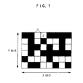
- Fig. 1 is a diagram illustrating one example of a digital image (signal light).
- binary digital data "0, 1" are converted into a digital image as "bright, dark”.
- signal light is Fraunhofer-diffracted (Fourier-transformed) by a lens so that a Fraunhofer's diffraction image shown in Fig. 2 is recorded on an optical recording medium.
- a spatial frequency of a data image is a normalized value such as digital data
- the Fraunhofer's diffraction image becomes a Fourier transformation image of the signal light.
- the Fraunhofer's diffraction image is referred to as the Fourier transformation image.
- the Fourier transformation image of the digital image is a regular diffraction grating, and has the 0-th order to n-th order components.
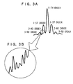
- Fig. 3A is a diagram illustrating a Fourier transformation spectrum
- Fig. 3B is a partially enlarged diagram of Fig. 3A.
- the Fourier transformation spectrum has peaks according to DC components of respective orders at bright spots.
- image edge component information necessary for recording and reproducing of an edge portion of a digital image
- Fig. 4 is a diagram schematically illustrating the Fourier transformation image of the signal light.
- a size of each bright spot reflects brightness.
- a spread of the Fourier transformation image to an x axial direction shown in Fig. 4 corresponds to a spatial frequency ⁇ x of the data image to the x axial direction shown in Fig. 1.
- Fig. 5 is a diagram illustrating one example of a filter that extracts a specific spatial frequency component of the Fourier transformation image shown in Fig. 4 (hereinafter, "specific Fourier spectrum").
- the filter 20 is arranged on an upper stream side of an optical recording medium and on a Fourier transformation plane of the signal light.
- the filter 20 is a light blocking body which has a pinhole 21 opposed to a position between the 0-th order and the 1-st order on the x axis of the Fourier transformation image.
- the filter 20 is disposed on the Fourier transformation plane, only a specific spatial frequency component between the bright spots can transmit through the filter 20, and the other spatial frequency components including a DC component are shielded.
- the filter 20 functions as a band-pass filter that allows only a specific spatial frequency component to transmit therethrough.
- the DC component useless exposure by means of the DC component is prevented so that S/N is improved, and only the image edge portion of the signal light is recorded efficiently.
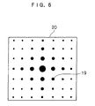
- Fig. 6 is a view illustrating another example of the filter.
- the filter 20 is a light transmission body which has a light blocking section 19 opposed to each bright spot of the Fourier transformation image.
- the light transmission body is formed by a transparent material for the signal light.
- Fig. 7 is a diagram illustrating one example of a constitution of the hologram recording apparatus.
- the hologram recording apparatus is provided with a light source 6 that emits a laser beam as coherent light.
- a beam splitter 12 that separates the laser beam into light for signal light and light for reference light is disposed on a laser beam emission side of the light source 6.
- a shutter 15 that blocks the light for signal light which transmits through the beam splitter 12 is disposed on a light transmission side of the beam splitter 12 so that the shutter 15 can be inserted to and retracted from an optical path.
- a lens system which is composed of collimating lenses 10a and 10b, and a Fourier transforming lens 7 is arranged in this order on a light transmission side of the shutter 15.
- a transmission type spatial light modulator 4 which is composed of a liquid crystal display element and the like and modulates the laser beam for signal light according to digital data supplied from a computer, not shown, so as to generate a digital image (signal light 1) of each page, is arranged between the collimating lens 10b and the Fourier transforming lens 7.
- the filter 20 which has the pinhole 21 is disposed on a light transmission side of the Fourier transforming lens 7.
- Reflection mirrors 13 and 14 which reflect the laser beam for reference light reflected by the beam splitter 12 and change the optical path to the direction of the optical recording medium 5, are arranged on a light reflection side of the beam splitter 12.
- the shutter 15 is retracted from the optical path by a driving device, not shown, so that a laser beam can pass.
- the laser beam which is emitted from the light source 6 is separated into two light beams of the light for signal light and the light for reference light by the beam splitter 12.
- the laser beam which transmits through the beam splitter 12 is collimated into a beam with a large diameter by the collimating lenses 10a and 10b so as to be irradiated as the light for signal light to the spatial light modulator 4.
- Digital data are input from the computer, not shown, into the spatial light modulator 4.
- the intensity of the laser beam for signal light is modulated according to the supplied digital data so that signal light 1 is generated.
- the generated signal light 1 is Fourier-transformed by the Fourier transforming lens 7.
- the Fourier-transformed signal light 1 passes through the pinhole 21 of the filter 20 so as to be irradiated to the optical recording medium 5.
- the laser beam reflected by the beam splitter 12 is reflected by the reflection mirrors 13 and 14, and passes through the pinhole 21 of the filter 20 so as to be irradiated as reference light 2 to the optical recording medium 5.
- the reference light 2 is irradiated to a region to which the Fourier-transformed signal light 1 is irradiated.
- the Fourier-transformed signal light 1 interferes with the reference light 2 in the optical recording medium 5, and the image edge portion of the signal light 1 is recorded as a hologram onto the optical recording medium 5.
- Figs. 8A and 8B are diagrams illustrating positions of the pinhole 21 formed on the light blocking body of the filter 20.
- the spatial light modulator 4 creates the digital image using the hologram recording apparatus shown in Fig. 7, and the digital image is Fourier-transformed by the Fourier transforming lens 7.
- the filter 20 is arranged on the Fourier transformation plane, and while the position of the pinhole 21 is being changed, a Fourier spectrum is extracted, and then the image is inversely Fourier-transformed by another lens (not shown) so as to be observed by a CCD camera (not shown).
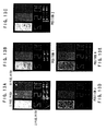
- the results are shown in Figs. 9A and 9B.
- the image to be observed is not a hologram reproduced image, but is an image obtained by inversely Fourier-transforming a specific Fourier spectrum transmitted through the filter 20 (hereinafter, "filtering image").
- the pinhole 21 is formed so as to be opposed to a position between the 0-th order and 1-st order on the x axis of the Fourier transformation image.
- the filter 20 in which the pinhole 21 is formed so as to be opposed to a position including the 0-th order (center) of the Fourier transformation image, as shown in Fig. 9A, a background of the image (DC component) is concentrated on the 0-th order. The background transmits through the filter 20 so that the image is restructured, and the DC component deteriorates contrast of data dots.
- the DC component of the image is essential, but the DC component is unnecessary on a digital data page expressed by minute dots. Therefore, only a specific spatial frequency component between the bright spots is extracted by the filter 20, and the other spatial frequency components including the DC component are shielded, so that useless exposure by means of the DC component is prevented and S/N is improved. As a result, only the image edge portion of the signal light is recorded efficiently. Further, since useless exposure is prevented, loss of a dynamic range of the optical recording medium is prevented.
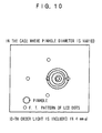
- Fig. 10 is a diagram illustrating a size of the pinhole 21 formed on the light blocking body of the filter 20.
- the diameter of the pinhole to be formed so as to be opposed to the position between the 0-th order and the 1-st order on the x axis of the Fourier transformation image is variously changed, and the filtering image is observed.
- the filter 20 is arranged adjacently to the optical recording medium 5, the hologram is recorded in a minute region whose size is approximately the same as an opening sectional area of the pinhole 21.
- f 300 mm
- the diameter of the pinhole 21 is gradually reduced to 4 mm, 3 mm, 2 mm, 1.5 mm, 1 mm and 0.4 mm, and the filtering image is observed.
- the results are shown in Figs. 11A to 11F.
- the digital image includes minute dot columns which are arranged at 2 pixel pitch, 5 pixel pitch and 10 pixel pitch.
- the minimum dot of the spatial light modulator corresponds to 1 pixel.
- a bandwidth r (mm) of the Fourier spectrum which is necessary for restructuring the digital data expressed by the diameter of the pinhole, namely, the minimum dot of the spatial light modulator without hiatus, is within a range that satisfies the following relationship (1), and more preferable that the range of the bandwidth r satisfies the following relationship (2).
- Fig. 12 is a diagram illustrating the position of the pinhole 21 to be formed on the light blocking body of the filter 20. As shown in Fig. 12, the position of the pinhole with diameter of 2 mm is variously changed from the position including the 0-th order (center) of the Fourier transformation image to the positions designated by 1 through 4, and the filtering image is observed. The results are shown in Figs. 13A to 13E.
- the minimum dot of the spatial light modulator is observed in all the filtering images regardless of the positions of the pinhole. This means that if the bandwidth r of the Fourier spectrum to be extracted is within the above range, the digital data of one data page can be recorded in one minute region (any one of the regions 1 to 4 in the drawings).
- one data page when a specific Fourier spectrum is extracted and recorded, as shown in Fig. 12 for example, one data page can be recorded in each of the minute regions 1 to 4 within the range of 0 ⁇ r ⁇ . That is to say, the recording regions can be miniaturized.
- conventional hologram recording if one data page is recorded in a region of 0 ⁇ r ⁇ 2 ⁇ , only when the range of 0 ⁇ r ⁇ is divided into four and recording is carried out, the recording density which is 16 times as high as that in the conventional recording can be achieved. It should be noted that only a hologram of one data page is recorded in each divided region, and thus multiplexing is not carried out.
- the recording regions are miniaturized and additionally the multiplex recording is carried out in each region, the recording density which is higher by at least 1 or more digit than the conventional recording system can be realized.
- the recording density which is higher by at least 1 or more digit than the conventional recording system can be realized.
- phase correlating multiplex recording can be carried out.
- the pinhole is formed so as to be opposed to the position between the 0-th order and the 1-st order on the x axis of the Fourier transformation image. Since the image edge portion is, however, superposed between other adjacent bright spots such as between the 1-st order and the 2-nd order and between the 2-nd order and the 3-rd order at a high frequency, when the pinhole is formed so as to be opposed to positions between another adjacent bright spots, useless exposure by means of a DC component is prevented and S/N is improved. As a result, only the image edge portion of the signal light is recorded efficiently.
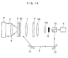
- Fig. 14 is a diagram illustrating one example of a constitution of the hologram reproducing apparatus.
- the hologram reproducing apparatus is constituted so that a Fourier transforming lens 8 and a two-dimensional photodetector 9 such as a photodetector array of CCD, CMOS array and the like are added to the hologram recording apparatus shown in Fig. 7. Digital data are recorded in the optical recording medium 5 according to the above-mentioned method.
- the shutter 15 is inserted into the optical path by the driving device, not shown, so that light for signal light is shielded.
- the reference light 2 passes through the pinhole 21 of the filter 20, so as to be irradiated to a region of the optical recording medium 5 where the hologram is recorded.
- the irradiated reference light 2 is diffracted by the hologram.
- diffraction light 3 is inversely Fourier-transformed by the Fourier transforming lens 8, so that a reproduced image where the image edge portion of the signal light is enhanced can be observed on a focal plane of the Fourier transforming lens 8.
- the reproduced image is detected by the photodetector 9, so that the digital data owned by the image edge portion of the signal light can be read.
- the above embodiment explains the example in which the light blocking body which has the pinhole is used as the filter, but the spatial light modulator can be used instead of such a light blocking body.
- the position of the pinhole can be changed programmably. For example as shown in Fig. 17, in the case where the spatial light modulator is used as the programmable filter 20a, the position of the light transmission section (pinhole) can be sequentially shifted to 21a, 21b and 21c. As a result, a data page can be recorded sequentially in different regions 23a, 23b and 23c of the optical recording medium 5a without moving the optical recording medium 5a.
- a rotor plate such as a turret can be used instead of the fixed type light blocking body.
- a data page can be recorded sequentially in different regions of the optical recording medium 5a.
- the turret which has the pinhole 21 d is used as the filter 20b, the turret can be rotated to a predetermined direction (direction of arrow A in the drawing), so that a data page can be recorded sequentially in different regions 23d, 23e and 23f of the optical recording medium 5b without moving the optical recording medium 5b.
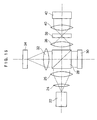
- Fig. 15 illustrates one example of a hologram recording/reproducing apparatus having a coaxial constitution.
- the hologram recording/reproducing apparatus is provided with the light source 22 which emits a laser beam as coherent light.
- the collimating lenses 24 and 26 are arranged on a laser beam emission side of the light source 22.
- the laser beam emitted from the light source 22 is collimated into a beam with large diameter by the collimating lenses 24 and 26 so as to enter the polarization beam splitter 28 and be reflected to the direction of the spatial light modulator 30.
- Digital data are input from the computer, not shown, into the spatial light modulator 30, and the intensity of the laser beam is modulated according to the supplied digital data so that the signal light and the reference light are generated.
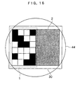
- a left half of the spatial light modulator 30 is used for displaying the data, and the intensity of incident light 44 which enters the left half of the spatial light modulator 30 is modulated so that the light reflected from the left half is the signal light 1. Meanwhile, the intensity or the phase of the incident light 44 at the right half of the spatial light modulator 30 is modulated by the data for reference light (random pattern or the like), so that light reflected from the right half is the reference light 2.
- the signal light and the reference light reflected from the spatial light modulator 30 enter the polarization beam splitter 28, so as to transmit through the polarization beam splitter 28.
- the Fourier transforming lens 32 is arranged on a light transmission side of the polarization beam splitter 28. Further, a reflection type spatial light modulator 34 is arranged as a programmable filter on a light transmission side of the Fourier transforming lens 32.
- the signal light and the reference light transmitted through the polarization beam splitter 28 are Fourier-transformed by the Fourier transforming lens 32.
- the Fourier-transformed signal light and reference light are irradiated to the spatial light modulator 34.
- the spatial light modulator 34 which is arranged as the programmable filter, filtrates (extracts) only a specific Fourier spectrum, and polarizes and modulates it so as to reflect it to the direction of the Fourier transforming lens 32.
- the filtrated signal light and reference light are inversely Fourier-transformed by the lens 32 so as to again enter the polarization beam splitter 28, and is reflected by the polarization beam splitter 28.
- An objective lens 36 with high NA is arranged on a light reflection side of the polarization beam splitter 28.
- the signal light and the reference light reflected by the polarization beam splitter 28 are Fourier-transformed by the objective lens 36, so as to be irradiated to the optical recording medium 38 simultaneously and coaxially.
- the reference light is irradiated to a region to which the Fourier-transformed signal light is irradiated.
- the Fourier-transformed signal light and reference light interfere with each other in the optical recording medium 38, so that an image edge portion of the signal light is recorded as a hologram on the optical recording medium 38.
- the reference light when the reference light is coaxial with the signal light, also the 0-th order component (DC component) of the reference light can be simultaneously cut (band-pass filtered) by the spatial light modulator 34 arranged as the programmable filter.
- the random pattern of the reference light is suitably selected, so that the pattern of the band-pass filtered Fourier spectrum can be changed greatly.
- a DC component (0-th order component) of the reference light which is always common is not included.
- a pseudo-random pattern when a pseudo-random pattern is selected as the reference light, a plurality of reference light beams without correlation can be obtained on a recording surface, so that multiplex recording can be performed in one region by using these reference light beams.
- an objective lens 40 with high NA and a two-dimensional photodetector 42 such as CMOS array are arranged on a reproduced light irradiation side of the optical recording medium 38, and when the hologram is reproduced, only the reference light is irradiated to a region of the optical recording medium 38 in which the hologram is recorded. The irradiated reference light is diffracted by the hologram.
- the diffraction light is inversely Fourier-transformed by the objective lens 40, a reproduced image in which the image edge portion of the signal light is enhanced can be observed on a focal plane of the objective lens 40.
- the reproduced image is detected by the photodetector 42 so that the digital data owned by the image edge portion of the signal light can be read.
- the reference light and the signal light pass through the common optical system and are Fourier-transformed simultaneously by the lens, the Fourier spectrum minimally necessary for recording data is extracted by the band-pass filter, and this is emitted to the medium so that the hologram is recorded. Since the reference light is also band-pass filtered light, the Fourier spectrum is changed according to a change in the reference light pattern, and multiplex recording can be carried out in one region without moving the optical recording medium.
- the above embodiment explains the example in which the pinhole having a circular shape is formed.
- the opening shape of the pinhole is not limited to the circular shape.
- a pinhole which has a polygonal shape or a rectangular shape may be formed.
- Fig. 1 the example where the respective signal light components are arranged without a gap is explained.
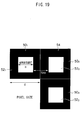
- black matrices 54 are provided around the signal light components and the like, and the signal light components 52 1 to 52 3 of the pixels 50 1 to 50 3 are arranged so as to be separated from one another.
- pixels 50 when it is not necessary to distinguish the pixels 50 1 to 50 3 , they are referred to as "pixels 50", and when it is not necessary to distinguish the signal light components 52 1 to 52 3 , they are referred to as "signal light components 52".
- the pixels 50 and the signal light components 52 have a concentric square shape.
- a length of one side of the pixels 50 pixel size
- a length of one side of the signal light components (openings) 52 is designated by a
- an arrangement interval of the signal light components 52 is N x a
- the aperture ratio expressed by a/d becomes 1/(N+1).
- the aperture ratio expressed by a/d is set to be larger than 0.5.
- removal of the DC component is equal to interference, with the signal light, of a plane wave which has uniform signal light and entire intensity and a phase difference ⁇ .
- the signal light becomes 0.
- this case is equal to a result of interfering the plane wave, having the same total intensity and the phase difference ⁇ , with original signal light.
- a bright portion becomes dark due to negative interference, and a dark portion becomes bright because only a light wave is applied to this portion.
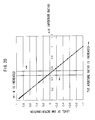
- a ratio of S/N after the DC component is eliminated to S/N before the DC component is eliminated (degree of S/N deterioration) is defined by the following formula.
- the aperture ratio expressed by a/d is preferably within the following range: 0 ⁇ a / d ⁇ 0.45.
- the aperture ratio expressed by a/d is preferably within the following range: 0.55 ⁇ a / d ⁇ 1.
- the above-mentioned data page can be created in the hologram recording apparatus shown in Fig. 7 by arranging a mask 58 so that it is close to a light emission side of a spatial light modulator 4.
- the mask 58 is a black matrix mask of the spatial light modulator 4 where openings 60 11 to 60 xy are provided corresponding to pixels 56 11 to 56 xy which are arranged in a matrix pattern of x rows and y columns.
- pixels 56 when it is not necessary to distinguish the pixels 56 11 to 56 xy , they are referred to as "pixels 56", and when it is not necessary to distinguish the openings 60 11 to 60 xy , they are referred to as "openings 60".
- the pixels 56 of the spatial light modulator 4 are arranged via the black matrix, the above-mentioned data page can be created similarly.
- the Fourier transformation image of a digital image is a regular diffraction grating, and its Fourier transformation spectrum has a peak according to DC component of each order at each bright spots.
- image edge component information which is necessary for recording and reproducing the edge portion of the digital image (referred to as "image edge component") is superposed between the bright spots at high frequency. That is to say, "image edge component” is all the spectrums other than the DC component of the Fourier spectrum of the digital image.
- the digital image when a specific spatial frequency component between the bright posts is extracted from the Fourier transformation image so as to be recorded, the digital image can be recorded and reproduced, and useless exposure due to the DC component is prevented so that S/N can be improved. Further, since a part of the Fourier transformation image is extracted and recorded, the recording region is miniaturized so that high-density recording can be realized.
- the effect is achieved that digital data can be recorded as a hologram at high S/N and in high density.
Landscapes
- Holo Graphy (AREA)
- Optical Recording Or Reproduction (AREA)
- Optical Head (AREA)
Applications Claiming Priority (2)
| Application Number | Priority Date | Filing Date | Title |
|---|---|---|---|
| JP2005134314 | 2005-05-02 | ||
| JP2005309117A JP4033208B2 (ja) | 2005-05-02 | 2005-10-24 | ホログラム記録方法及びホログラム記録装置 |
Publications (3)
| Publication Number | Publication Date |
|---|---|
| EP1720158A2 true EP1720158A2 (de) | 2006-11-08 |
| EP1720158A3 EP1720158A3 (de) | 2008-04-09 |
| EP1720158B1 EP1720158B1 (de) | 2010-10-13 |
Family
ID=36051576
Family Applications (1)
| Application Number | Title | Priority Date | Filing Date |
|---|---|---|---|
| EP06001033A Expired - Lifetime EP1720158B1 (de) | 2005-05-02 | 2006-01-18 | Verfahren und Vorrichtung zur Hologrammaufzeichnung |
Country Status (4)
| Country | Link |
|---|---|
| US (1) | US7535608B2 (de) |
| EP (1) | EP1720158B1 (de) |
| JP (1) | JP4033208B2 (de) |
| DE (1) | DE602006017468D1 (de) |
Cited By (3)
| Publication number | Priority date | Publication date | Assignee | Title |
|---|---|---|---|---|
| EP1983514A1 (de) * | 2007-04-19 | 2008-10-22 | THOMSON Licensing | Vorrichtung zum Lesen von und/oder Schreiben auf holografischen Speichermedien |
| EP1876591A3 (de) * | 2006-07-05 | 2009-12-09 | Sharp Kabushiki Kaisha | Hologrammaufzeichnungsvorrichtung, Hologrammwiedergabevorrichtung und Hologrammaufzeichnungsverfahren ohne Erfordernis der Positionierung einer Phasenmaske |
| EP2178084A1 (de) * | 2008-10-20 | 2010-04-21 | Thomson Licensing | Holografisches Speichersystem mit verbesserter Datenseitenqualität |
Families Citing this family (11)
| Publication number | Priority date | Publication date | Assignee | Title |
|---|---|---|---|---|
| JP4387118B2 (ja) * | 2003-03-14 | 2009-12-16 | Tdk株式会社 | ホログラム記録再生装置 |
| JP4389919B2 (ja) * | 2006-10-12 | 2009-12-24 | ソニー株式会社 | ホログラム再生装置及びホログラム再生方法 |
| US20100172003A1 (en) * | 2007-06-11 | 2010-07-08 | Pioneer Corporation | Hologram apparatus and recording and reproducing method of the same |
| JP2009058653A (ja) * | 2007-08-30 | 2009-03-19 | Fuji Xerox Co Ltd | ホログラム再生装置、ホログラム再生方法、ホログラム記録装置、及びホログラム記録方法 |
| JP2009058654A (ja) * | 2007-08-30 | 2009-03-19 | Fuji Xerox Co Ltd | ホログラム再生装置、ホログラム再生方法、ホログラム記録装置、及びホログラム記録方法 |
| JP5081741B2 (ja) * | 2008-06-20 | 2012-11-28 | 株式会社日立製作所 | 光情報記録装置、光情報記録方法、光情報記録再生装置および光情報記録再生方法 |
| JP2010205381A (ja) * | 2009-03-06 | 2010-09-16 | Sony Corp | 再生装置、再生方法 |
| JP5953284B2 (ja) * | 2013-11-11 | 2016-07-20 | 日立コンシューマエレクトロニクス株式会社 | 光情報記録媒体、光情報記録装置、光情報記録方法、光情報再生装置、光情報再生方法。 |
| KR102452945B1 (ko) | 2015-08-27 | 2022-10-11 | 삼성전자주식회사 | 푸리에 변환을 수행하는 방법 및 장치 |
| CN110992991A (zh) * | 2019-12-31 | 2020-04-10 | 广东紫晶信息存储技术股份有限公司 | 一种单臂结构的全息数据存储装置 |
| US12298713B2 (en) | 2020-12-02 | 2025-05-13 | Korea Electronics Technology Institute | Hologram printing method and apparatus using mask |
Family Cites Families (7)
| Publication number | Priority date | Publication date | Assignee | Title |
|---|---|---|---|---|
| JP3608603B2 (ja) | 1998-08-18 | 2005-01-12 | 富士ゼロックス株式会社 | 光記録方法および光記録装置 |
| JP4214329B2 (ja) | 1998-08-20 | 2009-01-28 | 富士ゼロックス株式会社 | 光記録方法、光記録装置、光読み取り方法、光読み取り装置 |
| JP4045394B2 (ja) | 1999-07-02 | 2008-02-13 | 富士ゼロックス株式会社 | ホログラム記録方法、ホログラム再生方法およびフィルタリング方法 |
| US6538776B2 (en) | 2001-03-20 | 2003-03-25 | Imation Corp. | Self-referenced holographic storage |
| US6909529B2 (en) * | 2001-07-31 | 2005-06-21 | Inphase Technologies, Inc. | Method and apparatus for phase correlation holographic drive |
| JP2004198816A (ja) | 2002-12-19 | 2004-07-15 | Nippon Telegr & Teleph Corp <Ntt> | ホログラム記録方法、ホログラム記録装置、ホログラム再生装置およびホログラム再生方法 |
| US7239594B2 (en) | 2003-02-07 | 2007-07-03 | Imation Corp. | Self-referenced holography using element formed on a holographic medium |
-
2005
- 2005-10-24 JP JP2005309117A patent/JP4033208B2/ja not_active Expired - Fee Related
-
2006
- 2006-01-12 US US11/330,179 patent/US7535608B2/en not_active Expired - Fee Related
- 2006-01-18 DE DE602006017468T patent/DE602006017468D1/de not_active Expired - Lifetime
- 2006-01-18 EP EP06001033A patent/EP1720158B1/de not_active Expired - Lifetime
Non-Patent Citations (1)
| Title |
|---|
| None |
Cited By (8)
| Publication number | Priority date | Publication date | Assignee | Title |
|---|---|---|---|---|
| EP1876591A3 (de) * | 2006-07-05 | 2009-12-09 | Sharp Kabushiki Kaisha | Hologrammaufzeichnungsvorrichtung, Hologrammwiedergabevorrichtung und Hologrammaufzeichnungsverfahren ohne Erfordernis der Positionierung einer Phasenmaske |
| EP1983514A1 (de) * | 2007-04-19 | 2008-10-22 | THOMSON Licensing | Vorrichtung zum Lesen von und/oder Schreiben auf holografischen Speichermedien |
| EP1983513A1 (de) * | 2007-04-19 | 2008-10-22 | Deutsche Thomson OHG | Vorrichtung zum Lesen von und/oder Schreiben auf holografischen Speichermedien |
| CN101290780B (zh) * | 2007-04-19 | 2011-12-07 | 汤姆森特许公司 | 从全息存储介质读取并且/或写入到全息存储介质的装置 |
| US8284469B2 (en) | 2007-04-19 | 2012-10-09 | Thomson Licensing | Apparatus for reading from and/or writing to holographic storage media |
| EP2178084A1 (de) * | 2008-10-20 | 2010-04-21 | Thomson Licensing | Holografisches Speichersystem mit verbesserter Datenseitenqualität |
| EP2178083A1 (de) * | 2008-10-20 | 2010-04-21 | Thomson Licensing | Holografisches Speichersystem mit verbesserter Datenseitenqualität |
| US8208184B2 (en) | 2008-10-20 | 2012-06-26 | Thomson Licensing | Holographic storage system with improved data page quality |
Also Published As
| Publication number | Publication date |
|---|---|
| DE602006017468D1 (de) | 2010-11-25 |
| JP4033208B2 (ja) | 2008-01-16 |
| JP2006338851A (ja) | 2006-12-14 |
| US7535608B2 (en) | 2009-05-19 |
| EP1720158B1 (de) | 2010-10-13 |
| EP1720158A3 (de) | 2008-04-09 |
| US20060245020A1 (en) | 2006-11-02 |
Similar Documents
| Publication | Publication Date | Title |
|---|---|---|
| EP1720158B1 (de) | Verfahren und Vorrichtung zur Hologrammaufzeichnung | |
| US7755820B2 (en) | Two-dimensional modulation method for hologram recording and hologram apparatus with encoder for driving SLM displaying boundary portion | |
| KR100477783B1 (ko) | 홀로그래피프로세스및홀로그래피어레이의복제프로세스 | |
| EP1528442A1 (de) | Räumlicher optischer modulator | |
| US7239594B2 (en) | Self-referenced holography using element formed on a holographic medium | |
| WO2004013706A1 (ja) | ホログラム記録再生方法及びホログラム記録再生装置 | |
| CN101162591A (zh) | 用于从全息存储介质读取和/或向其写入的装置 | |
| JP5026331B2 (ja) | ホログラフィック記憶媒体からの読出しおよび/またはホログラフィック記憶媒体への書込みを行うための装置 | |
| JP4184574B2 (ja) | 位相相関多重化(pcm)ホログラフィックメモリシステム | |
| JPH09282437A (ja) | 光情報記録媒体及び光情報読み取り装置 | |
| EP1457994A2 (de) | Kompakte Vorrichtung zur Aufnahme und Wiedergabe von Hologrammen | |
| JP4581841B2 (ja) | ホログラム記録装置及びホログラム記録方法 | |
| US7952776B2 (en) | Hologram reading apparatus, hologram reading method, hologram recording apparatus and hologram recording method | |
| JP4506329B2 (ja) | ホログラム記録装置、情報処理装置及びホログラム記録方法 | |
| JP2005135479A (ja) | ホログラム記録再生装置、ホログラム記録再生方法、位相変調パターンの表示方法及び位相変調パターンの作成方法 | |
| JP5040482B2 (ja) | ホログラム記録装置、ホログラム再生装置、ホログラム記録方法及びホログラム再生方法 | |
| JP2009058654A (ja) | ホログラム再生装置、ホログラム再生方法、ホログラム記録装置、及びホログラム記録方法 | |
| JP2008275817A (ja) | ホログラム記録装置 | |
| JP2009009629A (ja) | ホログラム記録装置、ホログラム再生装置、ホログラム記録方法及びホログラム再生方法 | |
| JP2002221697A (ja) | 光情報処理装置 | |
| US20050180300A1 (en) | Multichannel parallel recording and reading for hyper large bandpass photonics memory | |
| KR20070016478A (ko) | 홀로그래픽 디지털 데이터 기록 재생 장치의 공간 광변조기 | |
| KR20060043593A (ko) | 홀로그램 기록 재생 장치 및 홀로그램 기록 재생 방법 | |
| JP2005121855A (ja) | ホログラム記録再生装置、ホログラム記録再生方法及び光ビームの位相変調方法 |
Legal Events
| Date | Code | Title | Description |
|---|---|---|---|
| PUAI | Public reference made under article 153(3) epc to a published international application that has entered the european phase |
Free format text: ORIGINAL CODE: 0009012 |
|
| 17P | Request for examination filed |
Effective date: 20060118 |
|
| AK | Designated contracting states |
Kind code of ref document: A2 Designated state(s): AT BE BG CH CY CZ DE DK EE ES FI FR GB GR HU IE IS IT LI LT LU LV MC NL PL PT RO SE SI SK TR |
|
| AX | Request for extension of the european patent |
Extension state: AL BA HR MK YU |
|
| PUAL | Search report despatched |
Free format text: ORIGINAL CODE: 0009013 |
|
| AK | Designated contracting states |
Kind code of ref document: A3 Designated state(s): AT BE BG CH CY CZ DE DK EE ES FI FR GB GR HU IE IS IT LI LT LU LV MC NL PL PT RO SE SI SK TR |
|
| AX | Request for extension of the european patent |
Extension state: AL BA HR MK YU |
|
| 17Q | First examination report despatched |
Effective date: 20080616 |
|
| AKX | Designation fees paid |
Designated state(s): DE FR GB |
|
| GRAP | Despatch of communication of intention to grant a patent |
Free format text: ORIGINAL CODE: EPIDOSNIGR1 |
|
| GRAS | Grant fee paid |
Free format text: ORIGINAL CODE: EPIDOSNIGR3 |
|
| GRAA | (expected) grant |
Free format text: ORIGINAL CODE: 0009210 |
|
| AK | Designated contracting states |
Kind code of ref document: B1 Designated state(s): DE FR GB |
|
| REG | Reference to a national code |
Ref country code: GB Ref legal event code: FG4D |
|
| REF | Corresponds to: |
Ref document number: 602006017468 Country of ref document: DE Date of ref document: 20101125 Kind code of ref document: P |
|
| PLBE | No opposition filed within time limit |
Free format text: ORIGINAL CODE: 0009261 |
|
| STAA | Information on the status of an ep patent application or granted ep patent |
Free format text: STATUS: NO OPPOSITION FILED WITHIN TIME LIMIT |
|
| 26N | No opposition filed |
Effective date: 20110714 |
|
| REG | Reference to a national code |
Ref country code: DE Ref legal event code: R097 Ref document number: 602006017468 Country of ref document: DE Effective date: 20110714 |
|
| PGFP | Annual fee paid to national office [announced via postgrant information from national office to epo] |
Ref country code: GB Payment date: 20130116 Year of fee payment: 8 Ref country code: FR Payment date: 20130204 Year of fee payment: 8 Ref country code: DE Payment date: 20130116 Year of fee payment: 8 |
|
| REG | Reference to a national code |
Ref country code: DE Ref legal event code: R119 Ref document number: 602006017468 Country of ref document: DE |
|
| GBPC | Gb: european patent ceased through non-payment of renewal fee |
Effective date: 20140118 |
|
| REG | Reference to a national code |
Ref country code: DE Ref legal event code: R119 Ref document number: 602006017468 Country of ref document: DE Effective date: 20140801 |
|
| PG25 | Lapsed in a contracting state [announced via postgrant information from national office to epo] |
Ref country code: DE Free format text: LAPSE BECAUSE OF NON-PAYMENT OF DUE FEES Effective date: 20140801 |
|
| REG | Reference to a national code |
Ref country code: FR Ref legal event code: ST Effective date: 20140930 |
|
| PG25 | Lapsed in a contracting state [announced via postgrant information from national office to epo] |
Ref country code: GB Free format text: LAPSE BECAUSE OF NON-PAYMENT OF DUE FEES Effective date: 20140118 Ref country code: FR Free format text: LAPSE BECAUSE OF NON-PAYMENT OF DUE FEES Effective date: 20140131 |