EP1720161A1 - Optisches objektsystem, optische erfassungseinrichtung und optische informationsaufzeichnungs/wiedergabeeinrichtung - Google Patents
Optisches objektsystem, optische erfassungseinrichtung und optische informationsaufzeichnungs/wiedergabeeinrichtung Download PDFInfo
- Publication number
- EP1720161A1 EP1720161A1 EP05710423A EP05710423A EP1720161A1 EP 1720161 A1 EP1720161 A1 EP 1720161A1 EP 05710423 A EP05710423 A EP 05710423A EP 05710423 A EP05710423 A EP 05710423A EP 1720161 A1 EP1720161 A1 EP 1720161A1
- Authority
- EP
- European Patent Office
- Prior art keywords
- light flux
- optical
- light
- wavelength
- optical system
- Prior art date
- Legal status (The legal status is an assumption and is not a legal conclusion. Google has not performed a legal analysis and makes no representation as to the accuracy of the status listed.)
- Withdrawn
Links
Images



Classifications
-
- G—PHYSICS
- G11—INFORMATION STORAGE
- G11B—INFORMATION STORAGE BASED ON RELATIVE MOVEMENT BETWEEN RECORD CARRIER AND TRANSDUCER
- G11B7/00—Recording or reproducing by optical means, e.g. recording using a thermal beam of optical radiation by modifying optical properties or the physical structure, reproducing using an optical beam at lower power by sensing optical properties; Record carriers therefor
- G11B7/12—Heads, e.g. forming of the optical beam spot or modulation of the optical beam
- G11B7/135—Means for guiding the beam from the source to the record carrier or from the record carrier to the detector
- G11B7/1372—Lenses
- G11B7/1374—Objective lenses
-
- G—PHYSICS
- G11—INFORMATION STORAGE
- G11B—INFORMATION STORAGE BASED ON RELATIVE MOVEMENT BETWEEN RECORD CARRIER AND TRANSDUCER
- G11B7/00—Recording or reproducing by optical means, e.g. recording using a thermal beam of optical radiation by modifying optical properties or the physical structure, reproducing using an optical beam at lower power by sensing optical properties; Record carriers therefor
- G11B7/12—Heads, e.g. forming of the optical beam spot or modulation of the optical beam
- G11B7/135—Means for guiding the beam from the source to the record carrier or from the record carrier to the detector
- G11B7/1353—Diffractive elements, e.g. holograms or gratings
-
- G—PHYSICS
- G02—OPTICS
- G02B—OPTICAL ELEMENTS, SYSTEMS OR APPARATUS
- G02B13/00—Optical objectives specially designed for the purposes specified below
-
- G—PHYSICS
- G02—OPTICS
- G02B—OPTICAL ELEMENTS, SYSTEMS OR APPARATUS
- G02B5/00—Optical elements other than lenses
- G02B5/18—Diffraction gratings
-
- G—PHYSICS
- G11—INFORMATION STORAGE
- G11B—INFORMATION STORAGE BASED ON RELATIVE MOVEMENT BETWEEN RECORD CARRIER AND TRANSDUCER
- G11B7/00—Recording or reproducing by optical means, e.g. recording using a thermal beam of optical radiation by modifying optical properties or the physical structure, reproducing using an optical beam at lower power by sensing optical properties; Record carriers therefor
- G11B7/12—Heads, e.g. forming of the optical beam spot or modulation of the optical beam
- G11B7/125—Optical beam sources therefor, e.g. laser control circuitry specially adapted for optical storage devices; Modulators, e.g. means for controlling the size or intensity of optical spots or optical traces
- G11B7/127—Lasers; Multiple laser arrays
- G11B7/1275—Two or more lasers having different wavelengths
-
- G—PHYSICS
- G11—INFORMATION STORAGE
- G11B—INFORMATION STORAGE BASED ON RELATIVE MOVEMENT BETWEEN RECORD CARRIER AND TRANSDUCER
- G11B7/00—Recording or reproducing by optical means, e.g. recording using a thermal beam of optical radiation by modifying optical properties or the physical structure, reproducing using an optical beam at lower power by sensing optical properties; Record carriers therefor
- G11B7/12—Heads, e.g. forming of the optical beam spot or modulation of the optical beam
- G11B7/135—Means for guiding the beam from the source to the record carrier or from the record carrier to the detector
- G11B7/1392—Means for controlling the beam wavefront, e.g. for correction of aberration
- G11B7/13922—Means for controlling the beam wavefront, e.g. for correction of aberration passive
Definitions
- the present invention relates to an objective optical system, optical pickup apparatus and optical information recording/reproducing apparatus.
- the optical disk and magnetic optical disk using a blue-violet laser light source will be collectively called the high-density optical disk.
- recording/reproducing refers to recording and/or reproducing.
- DVDs and CDs Compact Disk
- the mere recording/reproducing of information using a high-density optical disk is not sufficient.
- the capability of similarly appropriate recording/reproducing of information using the DVDs and CDs owned by a user amounts to raising of the product value of an optical disk player/recorder for a high-density optical disk.
- an optical pickup apparatus mounted on the optical disk player/recorder for a high-density optical disk is preferred to have performances of ensuring the appropriate recording/reproducing of information, while maintaining the compatibility among three types of optical disks -- high-density optical disk, DVD and CD.
- One of the methods for ensuring appropriate recording/reproducing of information while maintaining the compatibility among the high-density optical disk, DVD and CD is to provide the optical system for high-density optical disk and the optical system for DVD and CD separately so that switching will be made between these two systems in response to the recording density of the optical disk for recording/reproducing of information.
- This method requires a plurality of optical systems. This is disadvantageous for reduction of physical size and production costs.
- an optical pickup apparatus having compatibility to provide commonality between the optical system for high-density optical disk and optical system for DVD and CD, and to minimize the number of optical parts constituting the optical pickup apparatus.
- Simplification of the configuration of the optical pickup apparatus and cost cutting are enhanced by providing commonality of the objective optical system arranged opposite to the optical disk.
- the objective optical system that can be used in common for a plurality of the optical disks, having different wavelengths of light flux, to be used for recording/reproducing, it is necessary to form in an objective optical system a phase structure where spherical aberration depends on wavelength.
- the known art of correcting the aberration is to provide a diffraction structure on the optical surface of the objective lens that is a constituent element of the optical pickup apparatus. (For example, see Patent Document 1: Official Gazette of Japanese Patent Tokkai 2002-298422 ).
- Patent Document 1 for aberration correction is configured in such a structure that a diffraction structure is provided on one surface of the objective lens. It provides a sufficient spherical aberration correcting function for recording/reproducing using two types of the optical disks using different wavelengths and/or having different protective substrate thicknesses.
- the following problem must be solved before a sufficient compatibility is achieved among three types of optical disks.
- the effect of diffraction is determined by the difference between the value of wavelength of a diffracted light times the diffraction order of the diffracted light and the value of wavelength of an other diffracted light times the diffraction order of the other diffracted light, and by the pitch of the diffraction. Therefore, the value, ( ⁇ 1 x 2) - ( ⁇ 3 x 1), is reduced when the ratio of the diffraction order of ⁇ 1 and ⁇ 3 is 2 to 1.
- the diffraction structure is designed with the blazed wavelength as the value close to even number times the wavelength ⁇ 1, for example, then there will be a reduced mutual diffraction in the light flux of the wavelength ⁇ 1 and that of ⁇ 3. This will result in difficult compatibility between the high-density optical disk and CD.
- the pitch of the ring-shaped zones of the diffraction structure must be reduced. If the pitch of the ring-shaped zones of the diffraction structure is reduced, it will become difficult to fabricate an optical element such as a lens and there will be a reduction in the amount of the transmitted light of the fabricated optical element. Further, a large aberration will be caused by the variation of the wavelength within the minute range of several nanometers due to the variation in the laser light source output and others. Such problems will be left unsolved.
- Another object of the present invention is to provide an objective optical system, an optical pickup apparatus and an optical information recording/reproducing apparatus, capable of ensuring the compatibility among three types of optical disks -- high-density optical disk using a blue-violet laser light source, DVD and CD --, and securing the amount of light as well as correcting spherical aberration.
- a further object of the present invention is to provide an objective optical system, optical pickup apparatus and optical information recording/reproducing apparatus, capable of reducing the generation of coma aberration also by shifting the objective lens by tracking, when recording or reproducing information using an optical disk, and providing excellent off-axis characteristics.
- an objective optical system used in an optical pickup apparatus wherein information is reproduced and/or recorded using a first optical disk having a protective layer thickness t1 using the light flux having a wavelength ⁇ 1 emitted from a first light source; information is reproduced and/or recorded using a second optical disk having a protective layer thickness t2 (t1 ⁇ t2) using the light flux having a wavelength ⁇ 2 ( ⁇ 1 ⁇ ⁇ 2) emitted from a second light source; and information is reproduced and/or recorded using a third optical disk having a protective layer thickness t3 (t2 ⁇ t3) using the light flux having a wavelength ⁇ 3 ( ⁇ 2 ⁇ ⁇ 3) emitted from a third light source;
- the above-mentioned objective optical system is preferred to comprise:
- an objective optical system used in an optical pickup apparatus wherein information is reproduced and/or recorded using a first optical disk having a protective layer thickness t1 using the light flux having a wavelength ⁇ 1 emitted from a first light source; information is reproduced and/or recorded using a second optical disk having a protective layer thickness t2 (t1 ⁇ t2) using the light flux having a wavelength ⁇ 2 ( ⁇ 1 ⁇ ⁇ 2) emitted from a second light source; and information is reproduced and/or recorded using a third optical disk having a protective layer thickness t3 (t2 ⁇ t3) using the light flux having a wavelength ⁇ 3 ( ⁇ 2 ⁇ ⁇ 3) emitted from a third light source;
- the above-mentioned objective optical system is preferred to comprise:
- the first and second embodiments it is possible to apply effective diffraction to that of the wavelength ⁇ 3 as well as the light flux of the wavelength ⁇ 1, by using the first diffraction structure and the odd-numbered order of diffraction of the diffracted light where the diffraction efficiency is the maximum, out of the diffracted light of the wavelength ⁇ 1, whereby compatibility based on diffraction is enhanced.
- the first optical path difference-generating structure allows the phase difference to be applied substantially to one or two of the light fluxes having the wavelength ⁇ 1, wavelength ⁇ 2 and wavelength ⁇ 3. This allows aberration correction to be applied to one or two light fluxes where insufficient correction or excessive correction is caused by the diffraction by the first diffraction structure, whenever required.
- magnification of image formation by the above-mentioned objective optical system is preferred to be substantially the same when information is reproduced or recorded on the first, second and third optical disks.
- This arrangement allows the spherical aberration to be corrected satisfactorily for the light fluxes of the wavelength ⁇ 1, wavelength ⁇ 2 and wavelength ⁇ 3. Further, this arrangement allows use of a plurality of light sources integrated in one package, thereby reducing the number of parts used in the optical pickup apparatus and contributing to miniaturization of the optical pickup apparatus and reduction in production costs.
- the magnification of image formation is preferred to be 0 (zero).
- the light flux of the wavelength ⁇ 1 be applied to the objective optical system as the parallel light flux
- the light flux of the wavelength ⁇ 2 be applied to the objective optical system as the parallel light flux
- the light flux of the wavelength ⁇ 3 be applied to the objective optical system as the parallel light flux
- all the light fluxes of wavelength ⁇ 1, wavelength ⁇ 2 and wavelength ⁇ 3 are applied to the objective optical system as parallel light fluxes.
- this arrangement improves the off-axis characteristics in the shit of the objective optical system (lens shift) at the time of tracking.
- the first optical path difference-generating structure is preferred to substantially provide a phase difference only to one or two of the light fluxes of wavelength ⁇ 1, wavelength ⁇ 2 and wavelength ⁇ 3.
- the first optical path difference-generating structure is preferred to substantially provide a phase difference only to the light flux of the wavelength ⁇ 2, out of the light fluxes of wavelength ⁇ 1, wavelength ⁇ 2 and wavelength ⁇ 3.
- a satisfactory light condensed spot is preferably formed on the information recording surface of the second optical disk by the first diffraction structure and the first optical path difference-generating structure.
- the first diffraction structure is preferably arranged in a serrated form and the first optical path difference-generating structure is preferably composed of a plurality of the ring-shaped zones, having a stepped structure, arranged concentrically about the optical axis.
- the first diffraction structure allows correction of the spherical aberration and/or the wavefront aberration of the light flux having wavelengths ⁇ 1 and ⁇ 3.
- the first optical path difference-generating structure permits correction of the spherical aberration and/or the wavefront aberration of the light flux having wavelength ⁇ 2.
- This arrangement allows the aberration correction function of each wavelength to be shared by a plurality of structures, without one particular diffraction structure taking charge thereof, with the result that the degree of freedom in lens designing is enhanced.
- the first optical path difference-generating structure preferably applies the phase difference only to the light flux having wavelength ⁇ 2, out of the light fluxes having wavelength ⁇ 1, wavelength ⁇ 2 and wavelength ⁇ 3.
- the first diffraction structure allows correction of the spherical aberration and/or the wavefront aberration of the light flux having wavelengths ⁇ 1 and ⁇ 3.
- the first optical path difference-generating structure permits correction of the spherical aberration and/or the wavefront aberration of the light flux having wavelength ⁇ 2.
- This arrangement allows the aberration correction function of each wavelength to be shared by a plurality of structures, without one particular diffraction structure taking charge thereof, with the result that the degree of freedom in lens designing is enhanced.
- the wavelength ⁇ 1, wavelength ⁇ 2 and wavelength ⁇ 3 satisfy the following conditions:
- changes in the diffraction efficiency can be minimized even if there is a variation in the wavelength of the light flux emitted from the light source (e.g. when the wavelength ⁇ 1 of the light flux emitted from the light source varies about several nanometers due to the light source manufacturing error and others), or there is a wavelength variation.
- the order of diffraction is lower, changes in the diffraction efficiency due to the variation in wavelength can be made smaller.
- the above-mentioned thirteenth embodiment is more preferable.
- This arrangement improves the signal-to-noise ratio, while minimizing the unwanted light fluxes, i.e. noise components that are not used for recording/reproducing of the information from the optical disk.
- ⁇ 1 > 85%, ⁇ 2 > 80% and ⁇ 3 ⁇ 75% be satisfied. This will better ensure the amounts of the diffracted light of L-th order and the diffracted light of M-th order, and will further improve the signal-to-noise ratio.
- the upper limits of the ⁇ 1 and ⁇ 2 and the lower limit of the ⁇ 3 are preferably 100% ⁇ ⁇ 1, 100% ⁇ ⁇ 2 and 40% ⁇ ⁇ 3.
- the objective optical system in an objective optical system described in any one of the first through fifteenth embodiments, it is preferred that the objective optical system be composed of a combination of at least two optical elements -- a first optical element arranged on the light source side and a second optical element arranged on the optical disk side.
- This arrangement increases the degree of freedom in the correction of aberration by the two-group configuration of the objective optical system consisting of two optical elements.
- the objective optical system in an objective optical system described in any one of the first through fifteenth embodiments, it is preferred that the objective optical system be composed of a combination of at least two optical elements -- a first optical element arranged on the light source side and a second optical element arranged on the optical disk side.
- the first optical element be provided with the first optical path difference-generating structure and the second optical element be provided with the first diffraction structure.
- This arrangement allows one optical element to be provided with one structure, and hence increases the tolerance in molding of the optical element as a single unit as compared to the case where one optical element is provided with two structures.
- the optical surface of the first optical element on the side of the light source be provided with the first optical path difference-generating structure.
- the amount of level differences in the direction of optical axis is greater than that in the serrated diffraction structure. This is likely to cause eclipse due to oblique incidence, and reduces diffraction efficiency. This arrangement minimizes such eclipse and reduction of diffraction efficiency.
- the first optical element be equipped with the first optical path difference-generating structure and first diffraction structure.
- the optical surface of the first optical element on the light source side be provided with the first optical path difference-generating structure.
- the focal distance of the first optical element is f1 and the focal distance of the second optical element is f2, the conditions of
- the paraxial curvature radius be approximately infinite on at least one of the surfaces of the first optical element.
- the above-mentioned objective optical system be provided with a second optical path difference-generating structure that does not substantially provide the phase differences to the light fluxes of the wavelength ⁇ 1 and wavelength ⁇ 2, but does substantially provide the phase difference to the light flux of the wavelength ⁇ 3;
- This configuration allows the second optical path difference-generating structure of the objective optical system to provide the each optical path difference P times that of the wavelength ⁇ 1 and Q times that of the wavelength ⁇ 2 when the light fluxes of the wavelength ⁇ 1 and wavelength ⁇ 2 pass through each ring-shaped zone of the second optical path difference-generating structure, whereby each phase difference is not substantially provided to the light fluxes of the wavelength ⁇ 1 and wavelength ⁇ 2.
- This arrangement ensures that the spherical aberration caused by the passage of the second optical path difference-generating structure offsets the spherical aberration caused by this light flux passing through the first diffraction structure and first optical path difference-generating structure, when the wavelength used varies within minute range (of the order of several nanometers). This reduces the amount of spherical aberration generated in the entire pickup apparatus when the wavelength used varies within minute range.
- the optical element equipped with the second optical path difference-generating structure is composed particularly of a plastic, this configuration is capable of minimizing the occurrence of aberration resulting from variations in refraction index when there is a change in the
- this arrangement allows the focal position of unwanted light flux to be removed from the focal position of the light flux used, thereby enhancing the detecting performance of the reflected light in the detector of the pickup apparatus. It should be noted that maintenance of the range of
- this arrangement allows the focal position of unwanted light flux to be removed from the focal position of the light flux used, thereby enhancing the detecting performance of the reflected light in the detector of the pickup apparatus. It should be noted that maintenance of the range of
- the focal position of the N-th order diffracted light and that of the (N ⁇ 1)-th order diffracted light be kept apart from each other 0.01 mm or more in the direction of optical axis, when information is reproduced and/or recorded using the third optical disk.
- this arrangement improves the detecting performance of the reflected light of N-order diffracted light in the optical detector of the optical pickup apparatus.
- an aperture restricting function be provided.
- This configuration reduces the number of parts constituting the objective optical system, and permits miniaturization and cost reduction.
- the aperture restricting function be fulfilled by the dichroic filter that allows only the light flux having a specific wavelength to pass through.
- the aperture restricting function be fulfilled by the function of condensing this light flux outside the information recording surface by assigning a diffraction to the light flux having a predetermined wavelength.
- This arrangement eliminates the need of installing a separate dichroic provided with special coating characterized by wavelength selecting capability, and also contributes to the reduction of physical size and production costs.
- At least one of the surfaces of the first optical element be concentrically arranged about the center of the optical axis, and divided into at least two areas -- a first area including the optical axis and a second area located around the first area; it is further preferred that the light flux of the wavelength ⁇ 3 having passed the second area be condensed outside the information recording surface of the third optical disk, when diffraction is applied to the light flux of the wavelength ⁇ 3 having passed the second area.
- a third area be provided around the second area, and the light flux of the wavelength ⁇ 1 having passed the third area be condensed outside the information recording surface of the first optical disk, or the light flux of the wavelength ⁇ 2 having passed the third area be condensed outside the information recording surface of the second optical disk.
- This configuration prevents an adverse effect of noise resulting from unwanted light flux unused for recording/reproducing of information from the optical disk.
- the first area be provided with the above-mentioned first diffraction structure.
- the first area be provided with the first optical path difference-generating structure, and the second area be divided into an area 2A closer to the optical axis and an area 2B farther from the optical axis, wherein the area 2A be provided with a second diffraction structure composed by formation of a plurality of ring-shaped zones having a stepped structure, arranged concentrically about the center of the optical axis, and the second diffraction structure substantially provides the phase difference to the light fluxes of the wavelengths ⁇ 2 and ⁇ 3, without providing it to the light flux of the wavelength ⁇ 1 substantially.
- t1 t2.
- the optical pickup apparatus preferably comprises:
- the optical information recording/reproducing apparatus preferably comprises an optical disk loading mechanism for loading an optical disk and the optical pickup apparatus described in the thirty seventh embodiment.
- the wavelength ⁇ 1 and wavelength ⁇ 3 preferably satisfy the following relation in order to achieve compatibility based on effective diffraction applied at a high diffraction efficiency: 1.6 ⁇ ⁇ 3 / ⁇ 1 ⁇ 2.3
- the wavelength ⁇ 3 is approximately twice the wavelength ⁇ 1 using the first diffraction structure, and since an odd-numbered number is employed to represent the order of diffraction of the diffracted light having the maximum diffraction efficiency, out of the diffracted light having the wavelength ⁇ 1, using the first diffraction structure, this arrangement provides more effective diffraction to the light flux of the wavelength ⁇ 3 as well to that of the wavelength ⁇ 1, with the result that compatibility based on diffraction is further enhanced.
- the optical disk using a blue-violet semiconductor laser or blue-violet SHG laser as a light source for recording/reproducing of information is collectively called a "high-density optical disk".
- Information recording/reproducing is carried out by the NA 0.85 objective optical system.
- Information recording/reproducing is carried out by an NA 0.65 through 0.67 objective optical system, in addition to the optical disk (e.g. Blue-ray disk) equipped with protective layer (protective film) having a thickness of around 0.1 mm, wherein the optical disk equipped with protective layer having a thickness of around 0.6 mm (e.g. HD, DVD) is also included.
- the optical disk provided with the protective layer having a thickness of about several nanometers through several tens of nanometer on the information recording surface, and the optical disk having a protective layer without any thickness are also included.
- the high-density optical disk also includes the magnetic optical disk using a blue-violet semiconductor laser or blue-violet SHG laser as a light source for recording/reproducing of information.
- the DVD is a generic term covering the DVD-based optical disk such as a DVD-ROM, DVD-Video, DVD-Audio, DVD-RAM, DVD-R, DVD-RW, DVD+R and DVD-RW.
- the CD is a generic term covering the CD-based optical disk such as a CD-ROM, CD-Audio, CD-Video, CD-R and CD-RW.
- the "objective optical system" of an optical pickup apparatus is defined as an optical system, arranged opposite to the optical disk, containing at least a condensing element having the function of condensing the light fluxes having different wavelengths emitted from the light source, onto the information recording surface of each of the optical disks having different recording densities.
- the objective optical system may consist of the condensing element alone.
- the objective optical system is provided by the optical system consisting of the optical element and the condensing element.
- the wording "does not substantially assign any phase difference” in the present specification is not restricted to reference to the state where there is no phase shift at all; this wording also refers to the state where the shift of the phase subsequent to assignment of the optical path difference is within ⁇ 0.2 ⁇ .
- the wording "does substantially assign a phase difference” refers to the state where the shift of the phase subsequent to assignment of the optical path difference is outside the range of ⁇ 0.2 ⁇ .
- magnification of image formation is substantially the same indicates the case where the difference in the magnification of image formation is within ⁇ 0.008.
- curvature radius is approximately infinite indicates the case where the curvature radius on the optical radium is equal to or greater than 200 mm. It is more preferred that the curvature radius on the optical radium be equal to or greater than 500 mm, and the surface be flat.
- optical path difference-generating structure refers to the structure where the incidence light flux is assigned with optical path difference.
- it includes the diffraction structure for causing a diffracted light to be produced on the light flux of specific wavelength, or the structure (phase difference-generating structure) for assigning phase difference to the light flux of specific wavelength.
- the high-density optical disk HD is characterized by the first wavelength ⁇ 1 of 408 nm, the first protective layer PL1 having a thickness t1 of 0.0875 mm, and the numerical aperture of NA1 of 0.85;
- the DVD is characterized by the second wavelength ⁇ 2 of 658 nm, the second protective layer PL2 having a thickness t2 of 0.6 mm, and the numerical aperture NA2 of 0.60;
- the CD is characterized by the third wavelength ⁇ 3 of 785 nm, the third protective layer PL3 having a thickness t3 of 1.2 mm, and the numerical aperture NA3 of 0.45.
- the relationship of the recording densities ( ⁇ 1, ⁇ 2 and ⁇ 3) among the first, second and third optical disks can be represented as ⁇ 3 ⁇ ⁇ 2 ⁇ ⁇ 1.
- the combinations among the wavelength, thickness of the protective layer, numerical aperture, recording density and magnification are not restricted to this example alone.
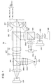
- the optical pickup apparatus PU comprises a blue-violet semiconductor laser LD1 (first light source) emitting light flux having a wavelength of 408 nm (the first light flux of the first wavelength ⁇ 1) when information is recorded and/or reproduced using the high-density optical disk HD, a first light detectors PD1 for receiving the light flux reflected from the information recording surface RL1 of the high-density optical disk HD, a red semiconductor laser LD2 (second light source) emitting light flux having a wavelength of 658 nm (the second light flux of the second wavelength ⁇ 2) when information is recorded and/or reproduced using the DVD, an infrared semiconductor laser LD3 (third light source) emitting light flux having a wavelength of 785 nm(the third light flux of the second wavelength ⁇ 3) when information is recorded and/or reproduced using the CD, a second light detectors PD2 for receiving the light flux reflected from the information recording surface RL2 of the DVD as well as the light flux reflected from the information recording surface RL3
- the optical pickup apparatus PU still further comprises a biaxial actuator AC1 for driving the objective optical system OBJ in the case of tracking and focusing, an aperture STO corresponding to the numerical aperture NA1 of the high-density optical disk HD, first through fourth polarizing beam splitters BS1, BS2, BS3 and BS4, first through third collimating lens COL1, COL2 and COL3, a beam expander EXP consisting of an negative lens E1 and a positive lens E2, a first sensor lens SEN1, a second sensor lens SEN2, and others.
- a biaxial actuator AC1 for driving the objective optical system OBJ in the case of tracking and focusing
- an aperture STO corresponding to the numerical aperture NA1 of the high-density optical disk HD
- first through fourth polarizing beam splitters BS1, BS2, BS3 and BS4 first through third collimating lens COL1, COL2 and COL3
- a beam expander EXP consisting of an negative lens E1 and a positive lens E2,
- the blue-violet semiconductor laser LD1 is made to emit light, as the optical path is shown by a solid line in Fig. 1.
- the diverged light flux emitted from the blue-violet semiconductor laser LD1 passes through the first polarizing beam splitter BS1, beam expander EXP and second polarizing beam splitter BS2.
- the light flux is changed a spot formed on the information recording surface RL1, through the first protective layer PL1 by the objective optical system OBJ.
- the effect of the objective optical system OBJ upon the wavelength ⁇ 1 will be described later.
- the objective optical system OBJ uses the biaxial actuator AC1 arranged on the periphery to perform focusing and tracking.
- the reflected light flux modulated by the information pit on the information recording surface RL1 is reflected by the first polarizing beam splitter BS1, and is assigned with astigmatism by the sensor lens SEN1. Then it is converted into the converged light flux by the third collimating lens COL3, and converges on the light receiving surface of the first light detector PD1.
- the output signal of the light detector PD1 can be used to read the information recorded on the high-density optical disk HD.
- red semiconductor laser LD2 When information is recorded and/or reproduced using the DVD, red semiconductor laser LD2 is made to emit light.
- the diverged light flux emitted from the red semiconductor laser LD2 passes through the third polarizing beam splitter and fourth polarizing beam splitter, as the light path is shown by a dotted line in Fig. 1, and is converted into the parallel light flux by the second collimating lens COL2. After that, it is reflected by the second polarizing beam splitter BS2, and is changed into a spot formed on the information recording surface RL2, through the second protective layer PL2 by the objective optical system OBJ.
- the effect of the objective optical system OBJ upon the light flux of the wavelength ⁇ 2 will be described later.
- the objective optical system OBJ uses the biaxial actuator AC1 arranged on the periphery to perform focusing and tracking.
- the reflected light flux modulated by the information pit on the information recording surface RL2 again passes through the objective optical system OBJ and is reflected by the second polarizing beam splitter BS2. It is then converted into the converged light flux by the second collimating lens COL2 and is reflected by the fourth polarizing beam splitter BS4. It is assigned with astigmatism by the second sensor lens SEN2 and converges on the light receiving surface of the second light detector PD2.
- the output signal of the light detector PD2 can be used to read the information recorded on the DVD.
- infrared semiconductor laser LD3 When information is recorded and/or reproduced using the CD, infrared semiconductor laser LD3 is made to emit light.
- the diverged light flux emitted from the infrared semiconductor laser LD3 is reflected by the third polarizing beam splitter BS2 and passes through the fourth polarizing beam splitter BS4 as the light path is shown by a dotted line in Fig. 1.
- the light flux After having been converted into the parallel light flux by the second collimating lens COL2, the light flux is reflected by the second polarizing beam splitter BS2, and is changed into a spot formed on the information recording surface RL3, through the third protective layer PL3 by the objective optical system OBJ.
- the effect of the objective optical system OBJ upon the light flux of the wavelength ⁇ 3 will be described later.
- the objective optical system OBJ uses the biaxial actuator AC1 arranged on the periphery to perform focusing and tracking.
- the reflected light flux modulated by the information pit on the information recording surface RL3 again passes through the objective optical system OBJ and is reflected by the second polarizing beam splitter BS2. It is then converted into the converged light flux by the second collimating lens COL2 and is reflected by the fourth polarizing beam splitter BS4. It is assigned with astigmatism by the second sensor lens SEN2 and converges on the light receiving surface of the second light detector PD2.
- the output signal of the light detector PD2 can be used to read the information recorded on the CD.
- the aberration-correcting element L1 includes a plastic lens having a refraction index nd of 1.5091 and Abbe's number vd of 56.5.
- the refractive index is 1.5242 for the wavelength ⁇ 1, 1.5064 for the wavelength ⁇ 2 and 1.5050 for the wavelength ⁇ 3.
- the light condensing element L2 is a plastic lens having a refraction index nd of 1.5435 and Abbe's number vd of 56.3.
- a flange formed integrally with the optically functioning section is provided on each of the peripheries of the optically functioning section of the aberration-correcting element L1 (area where the first light flux passes) and that of the light condensing element L2 (area where the first light flux passes).
- the aberration-correcting element L1 is made integral with the light condensing element L2 by bonding parts of such flanges with each other, so that they can be handled as one objective optical system.
- the aberration-correcting element L1 is made integral with the light condensing element L2, it is also possible to arrange such a configuration that they are made integral through the mirror frame of a separate member.
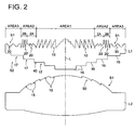
- the optical axis L is included in the optical surface S1 (light incidence surface) of the aberration-correcting element L1 on the side of the semiconductor laser beam source side, and is divided into:
- a first optical path difference-generating structure 10 is formed in the first area and a second diffraction structure 20 is formed in the second-A area.
- a diffraction structure 20' and a diffraction structure 30 are formed in each of the second-B area and the third area.
- the first optical path difference-generating structure 10, the second diffraction structure 20, the diffraction structure 20' in the second-B area and diffraction structure 30 in the third area each are composed of a plurality of the ring-shaped zones 13, having a stepped structure and consisting of a predetermined number of steps 11 and a discontinuous section 12, arranged concentrically about the optical axis L.
- the second diffraction structure 20 has a different number of the discontinuous sections 12 from that of the first optical path difference-generating structure 10.
- the first optical path difference-generating structure 10 and diffraction structure 20' of the second-B area have the same number of discontinuous sections.
- the first optical path difference-generating structure 10 is made of a plurality of ring-shaped zones 15, as shown in Fig. 4 schematically for example, and the cross sectional view including the optical axis L is serrated.
- the first optical path difference-generating structure 10 can be made of a plurality of ring-shaped zones 17 wherein the direction of the level difference of the step 16 is the same in the effective diameter, and the cross sectional view including the optical axis L is designed in a stepped form.
- the stepped structure is designed always in an ascending slope within the effective diameter around the optical axis L, whereby the level difference of the step 16 is oriented in the same direction within the effective diameter.
- the stepped structure is designed always in a descending slope within the effective diameter around the optical axis L, whereby the level difference of the step 16 is oriented in the same direction within the effective diameter.
- Figs. 3 through 5 schematically show the case where each structure is formed on a flat surface. It is also possible to make such arrangements that each structure is formed on a spherical surface or aspherical surface.
- the diffraction structure 20', diffraction structure 20' of the second-B area and diffraction structure 30 of the third area can be serrated in cross section, as shown in Fig. 4.
- the first optical path difference-generating structure 10 is set so as to substantially assign the phase difference only to the light flux of wavelength ⁇ 2, out of the light fluxes of wavelength ⁇ 1, wavelength ⁇ 2 and wavelength ⁇ 3 passing through the discontinuous section 12, without assigning it to the light fluxes of wavelength ⁇ 1 and wavelength ⁇ 3.
- the light flux of wavelength ⁇ 2 is subjected to diffraction.
- the diffracted light of wavelength ⁇ 2 resulting therefrom, having the highest diffraction efficiency, can be used for the DVD.
- n1 represents the refractive index of the aberration-correcting element L1 where the first optical path difference-generating structure 10 is formed, with respect to the light flux of the wavelength ⁇ 1;
- d1 (Fig. 3) shows the level difference of the step 11 of the stepped structure in the first optical path difference-generating structure 10, in the direction of optical axis L;
- ml (integer) indicates the number of the discontinuous sections 12; and
- d ⁇ 1/(n1-1).
- Arrangement is designed to ensure that 1.8 x d ⁇ d1 ⁇ 2.2 x d and 4 ⁇ m1 ⁇ 6 are satisfied based on the above-mentioned assumption.
- the level difference of the stepped structure in the first optical path difference-generating structure 10 is set to the depth approximately equivalent to an integral multiple of the wavelength ⁇ 1.
- the difference in optical path equivalent to approximately an integral multiple of the wavelength ⁇ 1 is produced between the adjacent steps. This means that phase difference is not substantially assigned to the light flux of the wavelength ⁇ 1.
- the incidence light flux of the wavelength ⁇ 1 passes by directly without being diffracted in the first optical path difference-generating structure 10.
- the difference in optical path equivalent to an integral multiple of the wavelength ⁇ 3 is produced between the adjacent steps, since the wavelength ⁇ 3 is approximately twice the wavelength ⁇ 1.
- the light flux of the wavelength ⁇ 3 passes by directly without being diffracted in the first optical path difference-generating structure 10, because phase difference is not substantially assigned thereto.
- phase difference conforming to the amount of level difference occurs to the incidence light flux of wavelength ⁇ 2.
- This diffraction for example, the diffracted light having an order of diffraction characterized by high diffraction efficiency can be utilized to record and/or reproduce information using the DVD, and to correct the chromatic aberration of the DVD or the spherical aberration resulting from temperature changes.
- the light flux of wavelength ⁇ 3 having passed through the first area AREA 1 are used to record and/or reproduce the information using the CD, thereby eliminating the need of the light flux of wavelength ⁇ 3 having passed through the second area AREA 2.
- the light flux of wavelength ⁇ 3 having passed through the second area AREA 2 is provided diffraction by the second diffraction structure 20 formed on the second-A area and the diffraction structure 20' formed on the second-B area, and the diffracted lights, generated thereby, having the order of diffraction characterized by a higher diffraction efficiency (e.g.
- the objective optical system OBJ is provided with an aperture restricting function corresponding to the numerical aperture NA3 by the above-mentioned "flaring", and longitudinal spherical aberration of the light flux having wavelength ⁇ 3 can be made discontinuous over the range from the first area AREA 1 to the second area AREA 2 by the second diffraction structure 20, thereby improving the accuracy of detecting the reflected light from the CD, of the light flux of wavelength ⁇ 3 in the second light detector PD2.
- a plurality of diffracted lights with respect to the light flux of wavelength ⁇ 3 e.g. diffracted lights of positive first order and negative first order
- have approximately the same diffraction efficiency e.g. about 40%
- the light flux of wavelength ⁇ 1 passing through the second area AREA 2 does so without being assigned substantially with phase difference, while the light flux of wavelength ⁇ 2 passing through the second area AREA 2 is assigned substantially with phase difference. Accordingly, information can be recorded and/or reproduced using the DVD, using the diffraction, e.g. using the diffracted lights having the order of diffraction characterized by a higher diffraction efficiency, and at the same time, the chromatic aberration of the DVD and spherical aberration resulting from temperature changes can be corrected.
- the light flux of wavelength ⁇ 2 and light flux of wavelength ⁇ 3 having passed through the third area AREA 3 are not necessary for recording/reproducing of the information from the DVD and CD.
- diffraction is applied by the diffraction structure 30 formed in the third area AREA 3, and the diffracted lights, generated thereby, having the order of diffraction characterized by a higher diffraction efficiency (e.g. 30% or higher) is "flared".
- a plurality of diffracted lights e.g. diffracted lights of positive first order and negative first order
- have approximately the same diffraction efficiency e.g. about 40%
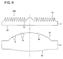
- the second optical path difference-generating structure 40 is formed on the optical surface S2 (light output surface) of the aberration-correcting element L1 on the optical disk side.
- the second optical path difference-generating structure 40 consists of a plurality of ring-shaped zones 17 where the direction of the level difference of the step 16 is the same within the effective diameter, as shown in Fig. 5.
- the cross section including the optical axis L is designed in a stepped structure, without substantially assigning phase difference to the incidence light fluxes of wavelength ⁇ 1 and wavelength ⁇ 2.
- the second optical path difference-generating structure 40 is set in such a way that the optical path difference P times that of the wavelength ⁇ 1 will be assigned when the incidence light flux of the wavelength ⁇ 1 passes through the ring-shaped zones 17, and the optical path difference Q times that of the wavelength ⁇ 2 will be assigned when the incidence light flux of the wavelength ⁇ 2 passes through the ring-shaped zones 17.
- h is the height from the optical axis
- B 2i is the coefficient of an optical path difference
- i is a natural number
- ⁇ is the blazed wavelength
- hmax is the height from an optical axis L as the numerical aperture NA1 of a high-density optical disk HD.
- refraction depends on the changes of the wavelength ⁇ 1 and wavelength ⁇ 2.
- the output angle of each light flux due to the diffraction exhibits in an increase.
- a decrease is shown as in -12 nm when (P, Q) is (5, 3), 4 nm when (P, Q) is (8, 5), and -12 nm when (P, Q) is (10, 6).
- the second optical path difference-generating structure is arranged so that ⁇ (hmax) > 0 will be satisfied. This arrangement allows the aberration resulting from the first diffraction structure 50 and first optical path difference-generating structure 10 to be reduced by the second optical path difference-generating structure 40, when a fluctuation of several nanometers in the wavelength has occurred to the light fluxes of the wavelength ⁇ 1 and wavelength ⁇ 2.
- the first diffraction structure 50 is arranged on the optical surface S1 (light incidence surface) of the light condensing element L2 on the semiconductor laser source side, as shown in Fig. 2.
- the first diffraction structure 50 has a plurality of ring-shaped zones 15 as shown in Fig. 4, and the cross section including the optical axis L is serrated.
- the first diffraction structure 50 can be the one shown in Fig. 3.
- the light fluxes of wavelengths ⁇ 1, ⁇ 2 and ⁇ 3 having passed the aberration-correcting element L1 are diffracted by the first diffraction structure 50.
- the L-th order diffracted light (where L denotes an odd number) of the light flux of wavelength ⁇ 1 resulting therefrom is designed to form a light condensed spot on the information recording surface RL1 of the high-density optical disk HD.
- the M-th order diffracted light (where M indicates an integer) of the light flux of the wavelength ⁇ 2 is designed to form a light condensed spot on the information recording surface RL2 of the DVD.
- the N-th order diffracted light (N indicates an integer) of the wavelength ⁇ 3 is designed to form a light condensed spot on the information recording surface RL3 of the DVD.
- the first diffraction structure 50 corrects aberration so that the L-th order diffracted light of wavelength ⁇ 1 will form a satisfactory light condensed spot on the information recording surface RL1 of the high-density optical disk HD; so that the M-th order diffracted light of wavelength ⁇ 2 will form a satisfactory light condensed spot o the information recording surface RL2 of the DVD using a phase difference provided when passing the first optical path difference-generating structure 10; and so that the N-th order diffracted light of wavelength ⁇ 3 will form a satisfactory light condensed spot on the information recording surface RL3 of the CD.
- the diffraction efficiency of the diffracted lights of L-th, M-th and N-th orders are assumed as ⁇ 1, ⁇ 2 and ⁇ 3, respectively, it is particularly preferred that the diffraction efficiency satisfies ⁇ 1 > 85%, ⁇ 2 > 80% and ⁇ 3 > 75%, in order to achieve compatibility among the high-density optical disk HD, DVD and CD.
- the objective optical system OBJ is designed to consists of two groups; the aberration-correcting element L1 and light condensing element L2. This allows the diffraction power and refraction power to be shared by two optical elements, and improves the freedom in designing.
- the objective optical system OBJ may be composed of a single lens; or the light incidence and output surfaces of this lens may be provided with the above-mentioned optical path difference-generating structure or diffraction structure.
- the aberration-correcting element L1 may be provided with the first diffraction structure 50 and first optical path difference-generating structure 10.
- the light condensing element L2 can be made of glass lens, with the result that generation of aberration due to temperature changes can be minimized.
- the light incidence surface S1 of the aberration-correcting element L1 be provided with the first optical path difference-generating structure 10.
- the first optical path difference-generating structure 10 is designed in a stepped structure consisting of a predetermined number of steps 11 and discontinuous sections 12 as shown in Fig. 3, the level difference in the direction of optical axis L will increase, as compared with the serrated structure shown in Fig. 4. This will cause eclipse and reduce the diffraction efficiency.
- the light incidence surface (light incidence surface S1 of the aberration-correcting element L1) is preferably provided with the first optical path difference-generating structure 10, where each light flux is composed of a parallel light flux.
- the lens is preferably designed in such a way that the
- an error in the assembling of the aberration-correcting element L1 and light condensing element L2 can be minimized by reducing the refraction force of the aberration-correcting element L1 in this manner.
- the optical surface is formed in an approximately flat surface, the first optical path difference-generating structure 10 and first diffraction structure 50 can be easily formed on the optical surface.
- the focal position of the diffracted light of N-th order when recording and/or reproducing the information using a CD and the focal position of the diffracted light of N ⁇ 1-th order are preferably kept apart from each other by 0.01 mm or more in the direction of optical axis L.
- the light incidence surface S1 of the aberration-correcting element L1 has been assumed to be divided into the first area AREA 1, second area AREA 2 and third area AREA 3.
- the light incidence surface S1 is divided into the first area AREA 1 and second area AREA 2, without the third area AREA 3 being provided, and diffraction is applied to the light flux of wavelength ⁇ 3 having passed through the second area AREA 2, whereby the light flux of wavelength ⁇ 3 is "flared".
- optical element constituting the objective optical system OBJ is equipped with the dichroic filter and liquid crystal phase control element, whereby the objective optical system is equipped with the aperture restricting function.
- An optical information recording apparatus capable of recording the optical information on the optical disk and/or reproducing the information recorded on the optical disk can be provided by mounting the optical pickup apparatus PU described in the above-mentioned embodiment, a drive apparatus for rotatably holding the optical disk and a control apparatus for controlling the drive of these devices (not illustrated)
- the optical pickup apparatus PU in the second embodiment is has approximately the same configuration as that of the first embodiment shown in Fig. 1. Its detailed description will be omitted to avoid duplication.
- the light incidence surface S1 of the aberration-correcting element L1 is provided with the first optical path difference-generating structure 10 comprising a plurality of ring-shaped zones arranged concentrically about the optical axis, wherein each of these ring-shaped zones consists of a predetermined number of steps and discontinuous sections and has a stepped structure.
- the light incidence surface S1 of the light condensing element L2 is provided with the first diffraction structure 50 consisting of a plurality of ring-shaped zones 15 wherein the cross section including the optical axis L is serrated.
- Table 1 shows the lens data of the first example.
- the height hmax from the optical axis L serving as the numerical aperture NA1 is 2.015 mm.
- the light incidence surface (fourth surface) and output surface (fifth surface) of the light condensing element are formed in the aspherical form, axially symmetric about the optical axis, defined by the equation obtained by substituting the coefficient of Table 1 in the following equation (3). Eq .
- the length of an optical path assigned to the light flux of each wavelength by the first optical path difference-generating structure and first diffraction structure 50 is defined by the equation obtained by substituting the coefficient of Table 1 into the optical path difference function in the following equation (4).
- Fig. 7 is a drawing representing the longitudinal spherical aberration of the light flux (for HD) of wavelength ⁇ 1, the light flux (for DVD) of wavelength ⁇ 2 and the light flux (for CD) of wavelength ⁇ 3.
- Fig. 7 suggests that the longitudinal spherical aberration is reduced within the required numerical aperture in all light fluxes.
- Table 2 shows the lens data in the second example.
- the height hmax from the optical axis L serving as the numerical aperture NA1 is 2.015 mm.
- the light incidence surface (fourth surface) and output surface (fifth surface) of the light condensing element are formed in the aspherical form, axially symmetric about the optical axis, defined by the equation obtained by substituting the coefficient of Table 2 in the above-mentioned equation (3), as in the case of the first example.
- the length of an optical path assigned to the light flux of each wavelength by the first optical path difference-generating structure and first diffraction structure is defined by the equation obtained by substituting the coefficient of Table 2 into the optical path difference function in the following equation (4), as in the case of the first example.
- the objective optical system concerning the second embodiment related to the HD and DVD as a high-density optical disk was used as a specific example for explanation. It goes without saying that the present invention is applicable to the first embodiment related to the BD (Blu-ray disk) as a high-density optical disk, and the objective optical system can be designed or redesigned in that case whenever required.
- the present invention is to provide an objective optical system, optical pickup apparatus and optical information recording/reproducing apparatus, capable of ensuring the compatibility among three types of optical disks -- high-density optical disk using a blue-violet laser light source, DVD and CD --, securing the amount of light and correcting spherical aberration.
Landscapes
- Physics & Mathematics (AREA)
- Optics & Photonics (AREA)
- General Physics & Mathematics (AREA)
- Optical Head (AREA)
- Lenses (AREA)
Applications Claiming Priority (2)
| Application Number | Priority Date | Filing Date | Title |
|---|---|---|---|
| JP2004053925 | 2004-02-27 | ||
| PCT/JP2005/002591 WO2005083694A1 (ja) | 2004-02-27 | 2005-02-18 | 対物光学系、光ピックアップ装置及び光情報記録再生装置 |
Publications (2)
| Publication Number | Publication Date |
|---|---|
| EP1720161A1 true EP1720161A1 (de) | 2006-11-08 |
| EP1720161A4 EP1720161A4 (de) | 2008-02-27 |
Family
ID=34879727
Family Applications (1)
| Application Number | Title | Priority Date | Filing Date |
|---|---|---|---|
| EP05710423A Withdrawn EP1720161A4 (de) | 2004-02-27 | 2005-02-18 | Optisches objektsystem, optische erfassungseinrichtung und optische informationsaufzeichnungs/wiedergabeeinrichtung |
Country Status (6)
| Country | Link |
|---|---|
| US (1) | US7715299B2 (de) |
| EP (1) | EP1720161A4 (de) |
| JP (1) | JPWO2005083694A1 (de) |
| KR (1) | KR20060115879A (de) |
| CN (1) | CN100449622C (de) |
| WO (1) | WO2005083694A1 (de) |
Families Citing this family (11)
| Publication number | Priority date | Publication date | Assignee | Title |
|---|---|---|---|---|
| KR101037031B1 (ko) * | 2002-09-30 | 2011-05-25 | 코니카 미노루따 호르딩구스 가부시끼가이샤 | 광학 요소, 대물 광학 요소 및 광학 픽업 장치 |
| JP4585513B2 (ja) * | 2004-03-19 | 2010-11-24 | パイオニア株式会社 | 光学素子、光ピックアップ及び光情報記録再生装置 |
| JP4850013B2 (ja) * | 2005-09-28 | 2012-01-11 | Hoya株式会社 | 光情報記録再生装置および光情報記録再生装置用対物レンズ |
| KR101055342B1 (ko) * | 2006-04-26 | 2011-08-09 | 가부시키가이샤 리코 | 광 픽업 및 광학 정보 처리 장치 |
| JP5393020B2 (ja) * | 2007-04-26 | 2014-01-22 | 株式会社リコー | 光ピックアップおよび光情報処理装置 |
| JP2009252309A (ja) * | 2008-04-08 | 2009-10-29 | Hoya Corp | 光情報記録再生装置用対物レンズ、および光情報記録再生装置 |
| TWI431328B (zh) | 2008-12-26 | 2014-03-21 | Canon Kk | 菲涅耳透鏡和射出成型 |
| JP5310386B2 (ja) * | 2009-06-18 | 2013-10-09 | ソニー株式会社 | 対物レンズ、光ピックアップ及び光ディスク装置 |
| JP5272985B2 (ja) * | 2009-09-11 | 2013-08-28 | 株式会社リコー | 回折光学素子及び光ピックアップ |
| JP5093634B2 (ja) * | 2010-10-22 | 2012-12-12 | コニカミノルタアドバンストレイヤー株式会社 | 光ピックアップ装置用の対物レンズ及び光ピックアップ装置 |
| CN109669278B (zh) * | 2018-11-21 | 2021-01-29 | 京东方科技集团股份有限公司 | 镜片和眼镜 |
Family Cites Families (28)
| Publication number | Priority date | Publication date | Assignee | Title |
|---|---|---|---|---|
| US5073007A (en) * | 1990-06-11 | 1991-12-17 | Holo-Or Ltd. | Diffractive optical element |
| CA2043978C (en) * | 1990-06-13 | 1999-08-10 | Yoshio Yoshida | Polarization diffraction element and polarization detector employing the same |
| KR100242646B1 (ko) * | 1997-03-28 | 2000-02-01 | 윤종용 | 홀로그램형 가변조리개를 사용하는 cd-r/dvd용 광기록/픽업헤드 |
| JP2943918B2 (ja) * | 1997-07-10 | 1999-08-30 | 日本電気株式会社 | 光ディスク装置 |
| JP3976457B2 (ja) * | 1998-10-28 | 2007-09-19 | 松下電器産業株式会社 | 光学ヘッド |
| DE60042812D1 (de) * | 1999-01-22 | 2009-10-08 | Konica Minolta Opto Inc | Optische Abtastvorrichtung, mit der optischen Abtastvorrichtung versehenes Aufnahme/Wiedergabegerät, optisches Element und Verfahren zur Datenaufnahme/wiedergabe |
| KR20010102007A (ko) * | 1999-12-10 | 2001-11-15 | 우에마쯔 도미지 | 대물 렌즈 및 광 픽업 장치 |
| JP3886313B2 (ja) * | 2000-01-26 | 2007-02-28 | パイオニア株式会社 | 光ピックアップ |
| JP3860953B2 (ja) * | 2000-07-07 | 2006-12-20 | 日本電産サンキョー株式会社 | 光ヘッド装置 |
| KR100335446B1 (ko) * | 2000-08-08 | 2002-05-04 | 윤종용 | 수차 보정소자 및 이를 채용한 광픽업장치 |
| US6873590B2 (en) * | 2001-03-09 | 2005-03-29 | Pentax Corporation | Objective lens for optical pick-up |
| JP4610118B2 (ja) * | 2001-03-30 | 2011-01-12 | Hoya株式会社 | 光ヘッド用対物レンズ |
| TWI239520B (en) * | 2001-10-12 | 2005-09-11 | Konica Corp | Objective lens, optical element, optical pick-up apparatus and optical information recording and/or reproducing apparatus equipped therewith |
| EP1313095B1 (de) * | 2001-11-15 | 2008-10-15 | Samsung Electronics Co. Ltd. | Kompatibles optisches Abstastgerät |
| DE60321414D1 (de) * | 2002-02-27 | 2008-07-17 | Ricoh Kk | Optischer Abtastkopf für verschiedene Wellenlängen |
| WO2003075267A1 (en) * | 2002-03-06 | 2003-09-12 | Matsushita Electric Industrial Co., Ltd. | Optical head device and optical information device using this, and computer, optical disk player, car navigation system, optical disy recorder and optical disk server using this optical information device |
| US6859319B2 (en) * | 2002-04-09 | 2005-02-22 | Sankyo Seiki Mfg. Co., Ltd. | Optical element, mold for molding optical element and optical pickup device |
| KR100648912B1 (ko) * | 2002-04-18 | 2006-11-24 | 마쯔시다덴기산교 가부시키가이샤 | 광학 소자, 광 헤드, 광 정보 기록 재생 장치, 컴퓨터,영상 기록 장치, 영상 재생 장치, 서버, 및 카 내비게이션시스템 |
| US7245407B2 (en) * | 2002-06-10 | 2007-07-17 | Matsushita Electric Industrial Co., Ltd. | Complex objective lens compatible with information media of different thicknesses |
| JP2004030724A (ja) * | 2002-06-21 | 2004-01-29 | Sharp Corp | 光ピックアップ装置 |
| JP4090291B2 (ja) * | 2002-06-26 | 2008-05-28 | 大日本スクリーン製造株式会社 | 光走査装置 |
| JP2004327003A (ja) * | 2002-07-26 | 2004-11-18 | Sharp Corp | 光ピックアップ |
| JP4341332B2 (ja) * | 2002-07-31 | 2009-10-07 | 旭硝子株式会社 | 光ヘッド装置 |
| US7577077B2 (en) * | 2002-09-05 | 2009-08-18 | Konica Corporation | Optical pickup apparatus and optical element |
| JP2004288346A (ja) * | 2002-10-18 | 2004-10-14 | Konica Minolta Holdings Inc | 光ピックアップ装置用の光学素子、カップリングレンズ及び光ピックアップ装置 |
| US7248409B2 (en) * | 2002-11-25 | 2007-07-24 | Matsushita Electric Industrial Co., Ltd. | Optical element, optical lens, optical head apparatus, optical information apparatus, computer, optical information medium player, car navigation system, optical information medium recorder, and optical information medium server |
| US7443778B2 (en) * | 2003-02-27 | 2008-10-28 | Matsushita Electric Industrial Co., Ltd. | Optical head device and optical information device using the same, computer, optical disk player, car navigation system, optical disk recorder, and optical disk server |
| JP4216155B2 (ja) * | 2003-09-19 | 2009-01-28 | フジノン株式会社 | 光記録媒体用対物光学系およびこれを用いた光ピックアップ装置 |
-
2005
- 2005-02-18 CN CNB2005800015881A patent/CN100449622C/zh not_active Expired - Fee Related
- 2005-02-18 KR KR1020067009735A patent/KR20060115879A/ko not_active Withdrawn
- 2005-02-18 WO PCT/JP2005/002591 patent/WO2005083694A1/ja not_active Ceased
- 2005-02-18 JP JP2006510407A patent/JPWO2005083694A1/ja active Pending
- 2005-02-18 EP EP05710423A patent/EP1720161A4/de not_active Withdrawn
- 2005-02-24 US US11/063,994 patent/US7715299B2/en not_active Expired - Fee Related
Also Published As
| Publication number | Publication date |
|---|---|
| EP1720161A4 (de) | 2008-02-27 |
| US20050190679A1 (en) | 2005-09-01 |
| US7715299B2 (en) | 2010-05-11 |
| WO2005083694A1 (ja) | 2005-09-09 |
| CN1906679A (zh) | 2007-01-31 |
| KR20060115879A (ko) | 2006-11-10 |
| CN100449622C (zh) | 2009-01-07 |
| JPWO2005083694A1 (ja) | 2007-11-29 |
Similar Documents
| Publication | Publication Date | Title |
|---|---|---|
| JP4775674B2 (ja) | 光ピックアップ装置 | |
| US20100054109A1 (en) | Condensing optical device, optical pickup, and optical disc apparatus | |
| JP4736071B2 (ja) | 光ピックアップ装置及び対物光学素子 | |
| EP1720161A1 (de) | Optisches objektsystem, optische erfassungseinrichtung und optische informationsaufzeichnungs/wiedergabeeinrichtung | |
| US7924683B2 (en) | Optical pickup apparatus with objective optical system and guiding optical system | |
| JPWO2007123112A1 (ja) | 光ピックアップ装置、光学素子及び光情報記録再生装置並びに光学素子の設計方法 | |
| EP1612783A2 (de) | Objektivlinse und optisches Abtastgerät | |
| JP4370619B2 (ja) | 光学素子、光ピックアップ装置及びドライブ装置 | |
| JP2005259332A (ja) | 光ピックアップ装置及び光ピックアップ装置用回折光学素子 | |
| US7525879B2 (en) | Objective optical element and optical pickup apparatus | |
| JP5024041B2 (ja) | 光ピックアップ装置用対物光学素子、光ピックアップ装置用光学素子、光ピックアップ装置用対物光学素子ユニット及び光ピックアップ装置 | |
| JPWO2008044475A1 (ja) | 対物光学素子ユニット及び光ピックアップ装置 | |
| JP4807258B2 (ja) | 対物レンズ及び光ピックアップ装置 | |
| JP2009037718A (ja) | 光ピックアップ装置及び対物光学素子 | |
| US6999399B2 (en) | Objective lens, optical pickup device, recorder and reproducer | |
| JPWO2005088625A1 (ja) | 対物光学素子及び光ピックアップ装置 | |
| JP4359894B2 (ja) | 光ピックアップ装置 | |
| US20030234987A1 (en) | Objective lens, optical pickup device, recorder and reproducer | |
| JPWO2008146675A1 (ja) | 光ピックアップ装置用の対物光学素子及び光ピックアップ装置 | |
| JP4573211B2 (ja) | 対物光学素子及び光ピックアップ装置 | |
| JPWO2008126562A1 (ja) | 光ピックアップ装置用の対物光学素子ユニット及び光ピックアップ装置 | |
| US20100208567A1 (en) | Objective Lens and Optical Pickup Apparatus | |
| JP2009181645A (ja) | 対物光学素子及び光ピックアップ装置 | |
| JP2007103011A (ja) | 光ピックアップ装置用対物レンズ及び光ピックアップ装置 | |
| JPWO2008114593A1 (ja) | 光ピックアップ装置及び対物光学素子 |
Legal Events
| Date | Code | Title | Description |
|---|---|---|---|
| PUAI | Public reference made under article 153(3) epc to a published international application that has entered the european phase |
Free format text: ORIGINAL CODE: 0009012 |
|
| 17P | Request for examination filed |
Effective date: 20060607 |
|
| AK | Designated contracting states |
Kind code of ref document: A1 Designated state(s): DE FR GB |
|
| DAX | Request for extension of the european patent (deleted) | ||
| RBV | Designated contracting states (corrected) |
Designated state(s): DE FR GB |
|
| A4 | Supplementary search report drawn up and despatched |
Effective date: 20080130 |
|
| 17Q | First examination report despatched |
Effective date: 20080731 |
|
| STAA | Information on the status of an ep patent application or granted ep patent |
Free format text: STATUS: THE APPLICATION IS DEEMED TO BE WITHDRAWN |
|
| 18D | Application deemed to be withdrawn |
Effective date: 20090211 |