EP1720162A2 - Appareil de lecture de disque et procédé de correction d'aberrations sphériques - Google Patents
Appareil de lecture de disque et procédé de correction d'aberrations sphériques Download PDFInfo
- Publication number
- EP1720162A2 EP1720162A2 EP06005909A EP06005909A EP1720162A2 EP 1720162 A2 EP1720162 A2 EP 1720162A2 EP 06005909 A EP06005909 A EP 06005909A EP 06005909 A EP06005909 A EP 06005909A EP 1720162 A2 EP1720162 A2 EP 1720162A2
- Authority
- EP
- European Patent Office
- Prior art keywords
- spherical aberration
- optical disk
- correction value
- recording layers
- laser beam
- Prior art date
- Legal status (The legal status is an assumption and is not a legal conclusion. Google has not performed a legal analysis and makes no representation as to the accuracy of the status listed.)
- Withdrawn
Links
Images




Classifications
-
- G—PHYSICS
- G11—INFORMATION STORAGE
- G11B—INFORMATION STORAGE BASED ON RELATIVE MOVEMENT BETWEEN RECORD CARRIER AND TRANSDUCER
- G11B7/00—Recording or reproducing by optical means, e.g. recording using a thermal beam of optical radiation by modifying optical properties or the physical structure, reproducing using an optical beam at lower power by sensing optical properties; Record carriers therefor
- G11B7/12—Heads, e.g. forming of the optical beam spot or modulation of the optical beam
- G11B7/135—Means for guiding the beam from the source to the record carrier or from the record carrier to the detector
- G11B7/1372—Lenses
- G11B7/1378—Separate aberration correction lenses; Cylindrical lenses to generate astigmatism; Beam expanders
-
- G—PHYSICS
- G11—INFORMATION STORAGE
- G11B—INFORMATION STORAGE BASED ON RELATIVE MOVEMENT BETWEEN RECORD CARRIER AND TRANSDUCER
- G11B7/00—Recording or reproducing by optical means, e.g. recording using a thermal beam of optical radiation by modifying optical properties or the physical structure, reproducing using an optical beam at lower power by sensing optical properties; Record carriers therefor
- G11B7/12—Heads, e.g. forming of the optical beam spot or modulation of the optical beam
- G11B7/135—Means for guiding the beam from the source to the record carrier or from the record carrier to the detector
- G11B7/1392—Means for controlling the beam wavefront, e.g. for correction of aberration
- G11B7/13925—Means for controlling the beam wavefront, e.g. for correction of aberration active, e.g. controlled by electrical or mechanical means
-
- G—PHYSICS
- G11—INFORMATION STORAGE
- G11B—INFORMATION STORAGE BASED ON RELATIVE MOVEMENT BETWEEN RECORD CARRIER AND TRANSDUCER
- G11B7/00—Recording or reproducing by optical means, e.g. recording using a thermal beam of optical radiation by modifying optical properties or the physical structure, reproducing using an optical beam at lower power by sensing optical properties; Record carriers therefor
- G11B7/08—Disposition or mounting of heads or light sources relatively to record carriers
- G11B7/085—Disposition or mounting of heads or light sources relatively to record carriers with provision for moving the light beam into, or out of, its operative position or across tracks, otherwise than during the transducing operation, e.g. for adjustment or preliminary positioning or track change or selection
-
- G—PHYSICS
- G11—INFORMATION STORAGE
- G11B—INFORMATION STORAGE BASED ON RELATIVE MOVEMENT BETWEEN RECORD CARRIER AND TRANSDUCER
- G11B7/00—Recording or reproducing by optical means, e.g. recording using a thermal beam of optical radiation by modifying optical properties or the physical structure, reproducing using an optical beam at lower power by sensing optical properties; Record carriers therefor
- G11B7/08—Disposition or mounting of heads or light sources relatively to record carriers
- G11B7/09—Disposition or mounting of heads or light sources relatively to record carriers with provision for moving the light beam or focus plane for the purpose of maintaining alignment of the light beam relative to the record carrier during transducing operation, e.g. to compensate for surface irregularities of the latter or for track following
-
- G—PHYSICS
- G11—INFORMATION STORAGE
- G11B—INFORMATION STORAGE BASED ON RELATIVE MOVEMENT BETWEEN RECORD CARRIER AND TRANSDUCER
- G11B7/00—Recording or reproducing by optical means, e.g. recording using a thermal beam of optical radiation by modifying optical properties or the physical structure, reproducing using an optical beam at lower power by sensing optical properties; Record carriers therefor
- G11B7/08—Disposition or mounting of heads or light sources relatively to record carriers
- G11B7/09—Disposition or mounting of heads or light sources relatively to record carriers with provision for moving the light beam or focus plane for the purpose of maintaining alignment of the light beam relative to the record carrier during transducing operation, e.g. to compensate for surface irregularities of the latter or for track following
- G11B7/0941—Methods and circuits for servo gain or phase compensation during operation
-
- G—PHYSICS
- G11—INFORMATION STORAGE
- G11B—INFORMATION STORAGE BASED ON RELATIVE MOVEMENT BETWEEN RECORD CARRIER AND TRANSDUCER
- G11B7/00—Recording or reproducing by optical means, e.g. recording using a thermal beam of optical radiation by modifying optical properties or the physical structure, reproducing using an optical beam at lower power by sensing optical properties; Record carriers therefor
- G11B2007/0003—Recording, reproducing or erasing systems characterised by the structure or type of the carrier
- G11B2007/0009—Recording, reproducing or erasing systems characterised by the structure or type of the carrier for carriers having data stored in three dimensions, e.g. volume storage
- G11B2007/0013—Recording, reproducing or erasing systems characterised by the structure or type of the carrier for carriers having data stored in three dimensions, e.g. volume storage for carriers having multiple discrete layers
Definitions
- the present invention contains subject matter related to Japanese Patent ApplicationNo. 2005-107176 filed in the Japanese Patent Office on April 4, 2005, the entire contents of which being incorporated herein by refererice.
- the invention relates to a disk drive apparatus and a spherical aberration correcting method which are suitable for use in an optical disk having a plurality of recording layers.
- CD-R Compact Disc-Recordable
- CD-RW Compact Disc-ReWritable
- DVD-R DVD Recordable
- DVD+R DVD + R format
- DVD-RW DVD Re-Writable
- DVD+RW DVD + RW format
- a DVD-R double-layered disk is known as a recordable optical disk having a plurality of recording layers.
- the recording and reproduction of data onto/from the optical disk are executed by irradiating a laser beam onto the recording layer of the optical disk from an optical pickup. That is, the laser beam is converged onto the recording layer and a light spot is formed on the recording layer. Upon recording, a recording mark is formed by altering a recording film by energy of the laser beam. Upon reproduction, the reflection light of the laser beam from the recording layer is detected by a photodetector and the recording mark (pit) is read.
- a track pitch is set to about 0.74 ⁇ m and a diameter of the light spot which is formed on the recording layer is set to, for example, about 0.89 ⁇ m.
- the laserbeam is irradiated from a laser beam source, enters an objective lens through a beam splitter or the like, and is converged by the obj ective lens, thereby forming the light spot onto the recording layer of the optical disk.
- An image of the light spot is deformed by a spherical aberration which is caused by optical imperfection of the objective lens.
- a spherical aberration which is caused by optical imperfection of the objective lens.
- a liquid crystal optical device on which concentric patterns have been formed is arranged on a position of the objective lens opposite to the disk surface side and transmittance of the liquid crystal device is concentrically controlled on the basis of a predetermined correction value.
- a correction value for example, it is possible to use a value obtained by measuring a reproduction jitter, an amplitude of a reproduction RF signal, a push-pull signal by a 2-split photodetector, or the like. In such a case, it is necessary to separately execute the recording/reproducing operation in order to obtain the correction value.
- an adjustment value of the spherical aberration can be determined in accordance with a thickness of transmission layer.
- a method whereby the thickness of transmission layer is measured by a focusing search and used for correction of the spherical aberration has been proposed in JP-A-2003-91851 .
- the thickness of transmission layer is set to 600 ⁇ m ⁇ 10 ⁇ m. If an error for the thickness of 600 ⁇ m lies within a range of ⁇ 10 ⁇ m, even if the adjustment value is mechanically determined for the thickness of 600 ⁇ m, there is no problem.
- the double-layered disk of the DVD since an interval between the two recording layers is set to about 60 ⁇ m and a difference of a value which is difficult to be ignored occurs between the best adjustment values in the two recording layers, it is necessary to make the adjustment with respect to each layer.
- the recording and reproduction for obtaining the correction value need to be executed every adjustment, in the case of the disk having a plurality of recording layers, there is aproblemthat it takes a long time for the adjustment.
- the optical disk drive makes focusing control so that a light spot is formed on the L0 layer. After that, the recording and reproduction for obtaining the correction value are executed and the correction value is measured. Subsequently, similarly, the optical disk drive makes focusing control so that a light spot is formed on the L1 layer. After that, the recording and reproduction for obtaining the correction value are executed again and the correction value is measured.
- a disk drive apparatus comprising: an optical pickup irradiating a laser beam onto an optical disk having one or more recording layers through an objective lens and receiving the laser beam reflected from the optical disk; a driving unit moving the objective lens in an optical axial direction of the laser beam to the optical disk in accordance with a driving signal; an interlayer distance measuring unit measuring interlayer distances of a plurality of recording layers of the optical disk; and a spherical aberration correcting unit obtaining a spherical aberration correction value for correcting a spherical aberration due to the objective lens to one of the plurality of recording layers, wherein a spherical aberration correction value to another one of the plurality of recording layers is obtained on the basis of the interlayer distance measured by the interlayer distance measuring unit and the spherical aberration correction value to the one recording layer obtained by the spherical aberration correcting unit.
- a spherical aberration correcting method comprising: a step of irradiating a laser beam onto an optical disk having a plurality of recording layers through an objective lens by an optical pickup and receiving the laser beam reflected from the optical disk; an interlayer distance measuring step of measuring interlayer distances of the plurality of recording layers of the optical disk; and a spherical aberration correcting step of obtaining a spherical aberration correction value for correcting a spherical aberration due to the objective lens to one of the plurality of recording layers, wherein a spherical aberration correction value to another one of the plurality of recording layers is obtained on the basis of the interlayer distance measured in the interlayer distance measuring step and the spherical aberration correction value to the one recording layer obtained in the spherical aberration correcting step.
- the interlayer distances of the plurality of recording layers of the optical disk having the plurality of recording layers are measured.
- the spherical aberration correction value for correcting the spherical aberration due to the objective lens to one of the plurality of recording layers is obtained.
- the spherical aberration correction value to another one of the plurality of recording layers is obtained on the basis of the interlayer distances and the spherical aberration correction value to the one recording layer. Therefore, a time of the spherical aberration correcting process to the optical disk having the plurality of recording layers is shortened.
- the interlayer distances of the plurality of recording layers of the optical disk having a plurality of recording layers are obtained.
- the spherical aberration correction value to the one recording layer is obtained.
- the spherical aberration correction value to the other recording layer is obtained on the basis of the spherical aberration correction value obtained to the one recording layer and the interlayer distances. Therefore, there is an effect that a time which is necessary for the spherical aberration correction can be shortened.
- Fig. 1 shows a construction of an example of an optical disk drive apparatus 1 which can be applied to the embodiment of the invention.
- the whole operation of the optical disk drive apparatus 1 is controlled by a microcomputer 27.
- the microcomputer 27 is constructed by, for example, a microprocessor and controls the operation of the optical disk drive apparatus 1 on the basis of a program which has previously been stored in a ROM (Read Only Memory) (not shown) by using a RAM (similarly, not shown) as a work memory.
- ROM Read Only Memory
- RAM similarly, not shown
- the program data which is updated is supplied from, for example, a host I/F (interface) 26.
- An optical disk 10 is fitted to a shaft 21 of a spindle motor 20 by a clamping mechanism (not shown) and can be rotated by the spindle motor 20.
- An optical pickup 22 is arranged at a position which faces the recording surface of the optical disk 10.
- the optical pickup 22 is put on a sled 24 which can be moved in the radial direction of the optical disk 10 by a sled motor 23 and is moved in the radial direction of the optical disk 10 together with the sled 24.
- the optical pickup 22 has a laser beam source, a beam splitter, a photodetector, an objective lens, an actuator to make the objective lens movable, and the like.
- a laser beam emitted from the laser beam source is transmitted through the beam splitter, converged by the objective lens through a liquid crystal optical device 50 which is driven by a liquid crystal driver 51 under the control of the microcomputer 27, and irradiated onto the recording surface of the optical disk 10.
- the laser beam is reflected by the recording surface of the optical disk 10, enters the beam splitter through the objective lens, is reflected by the beam splitter, and reaches the photodetector.
- the photodetector outputs a signal corresponding to intensity of the incident laser beam.
- the actuator is driven by a servo control unit 28 under the control of the microcomputer 27 and moves the objective lens in the optical axial direction and the direction (disk radial direction) perpendicular to the optical axis.
- a servo control unit 28 By moving the objective lens in the optical axial direction by the actuator, focusing control is made.
- tracking control is made.
- An output of the optical pickup 22 is supplied to a signal processing unit 25.
- the signal processing unit 25 forms a focusing error signal, a tracking error signal, and the like on the basis of the output of the optical pickup 22 and supplies them to the microcomputer 27.
- the microcomputer 27 supplies a control signal to the servo control unit 28 on the basis of the focusing error signal and the tracking error signal.
- the servo control unit 28 makes various kinds of servo control such as spindle servo, sled servo, servo (focusing servo, tracking servo) for the objective lens, and the like on the basis of the supplied control signal.
- the microcomputer 27 properly obtains a correction value on the basis of the output of the optical pickup 22. On the basis of the correction value, the microcomputer 27 corrects the spherical aberration which is caused when the laser beam is irradiated onto the recording layer of the optical disk 10.
- the spherical aberration correction is made by, for example, a method whereby the liquid crystal optical device 50 is driven by controlling the liquid crystal driver 51 and the intensity of the laser beam is partially controlled.
- the spherical aberration correction can be also made by moving the objective lens in the optical axial direction by the actuator. Further, the spherical aberration correction can be also made by a combination of those two methods.
- the correction value can be obtained by, for example, a method whereby the trial writing is executed by using a non-recording portion or the like in a PCA (Power Calibration Area) or a lead-in area which is arranged on the inner rim side of the optical disk 10 and the reproduction jitter, RF signal, push-pull signal, or the like is measured on the basis of a reproduction signal of the non-recording portion.
- PCA Power Calibration Area
- the liquid crystal driver 51 is controlled so as to drive the liquid crystal optical device 50 in such a direction as to reduce the reproduction jitter.
- the liquid crystal driver 51 is controlled in such a direction as to maximize them.
- a control value hereinbelow, referred to as a spherical aberration correction value
- a spherical aberration correction value used to correct the spherical aberration is stored in, for example, the RAM provided in the microcomputer 27.
- the optical disk 10 loaded into the optical disk drive apparatus 1 is a double-layered disk having two recording layers
- an interlayer distance between the two recording layers can be obtained on the basis of the focusing error signal and a driving signal to drive the actuator in the optical axial direction although the details will be explained hereinafter.
- the microcomputer 27 obtains a spherical aberration correction value in the other recording layer.
- a method of obtaining such a spherical aberration correction value for example, there is a method whereby a table showing the relation between the spherical aberration correction value in one recording layer and the interlayer distance is preliminarily stored in the ROM and the spherical aberration correction value in the other recording layer is obtained with reference to such a table. Such a value may be also obtained by a calculation.
- the signal processing unit 25 Upon recording, the signal processing unit 25 executes an error correction encoding process, a recording encoding process, and the like to the recording data supplied through the host I/F 26 and further executes predetermined signal processes such as a modulating process and the like, thereby forming a recording signal.
- the recording signal is supplied to the optical pickup 22 and modulated into the laser beam.
- the signal processing unit 25 executes predetermined processes such as RF signal process, binarizing process, PLL (Phase Locked Loop) synchronizing process, a decoding process of a recording code, and the like to the signal outputted from the optical pickup 22 and extracts digital data.
- the digital data outputted from the signal processing unit 25 is transferred to an external apparatus through the host I/F 26.
- Fig. 2 conceptually shows an optical path of an example in the optical pickup 22.
- the laser beam emitted from a laser beam source 30 constructed by a laser diode is divided into a main beam constructed by 0-th order light and two side beams constructed by primary light by, for example, a grating 31 and they enter a collimator lens 33 through a beam splitter 32.
- the laser beam is converted into parallel light by the collimator lens 33, enters an objective lens 34 through the liquid crystal optical device 50, is converged by the objective lens 34, and is irradiated onto the recording surface of the optical disk 10.
- the laser beam is reflected by the recording surface of the optical disk 10 and enters the beam splitter 32 through the obj ective lens 34 and the collimator lens 33.
- the reflected laser beam is reflected by the beam splitter 32 in a predetermined direction and enters a photodetector 40 through a cylindrical lens 35.
- the photodetector 40 is, for example, a 4-split photodetector whose photosensitive surfaces are divided into four areas by two lines which cross perpendicularly.
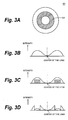
- the liquid crystal optical device 50 is constructed in such a manner that a concentric pattern 52 is arranged, a transmittance of the portion of the pattern 52 is changed by orienting the liquid crystal by applying an electric field on the basis of the pattern 52, and an intensity of the laser beam which is transmitted through the liquid crystal optical device 50 is partially changed. For example, if an intensity variation of the laser beam due to the spherical aberration exists as shown in Fig.
- the transmittance is partially controlled by the liquid crystal optical device 50, thereby attenuating the intensity of the laser beam by an amount schematically shown in a hatched region in Fig. 3C.
- the intensity of the laser beam is uniformed as schematically shown in Fig. 3D as compared with that shown in the example of Fig. 3B, so that the spherical aberration correction is made.
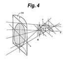
- the cylindrical lens 35 has a lens function only in one direction (y direction in the example of Fig. 4) of the light flux. Therefore, although a focal area converted by the cylindrical lens 35 occurs at a point B, this focal area does not become a point but becomes a straight line in the y direction (actually, an elliptic shape extending in the y direction).
- the light flux in the x direction is extended and coincides with an extent in the y direction at a point j and the focal area becomes a circular shape. After that, only the light flux in they direction is converged and focused in a straight line in the x direction (actually, an elliptic shape extending in the x direction) at a point A.
- Figs. 5A to 5C schematically show the state where the laser beam is received by the photodetector 40 through the cylindrical lens 35 as mentioned above.
- the four divided photosensitive surfaces of the photodetector 40 are labeled to A, B, C, and D, respectively.
- the photodetector 40 receives the laser beam in the state at the point B in Fig. 4.
- the laser beam is received in an elliptic shape extending in the y direction by the photosensitive surfaces of the photodetector 40.
- the distance between the optical disk 10 and the objective lens 34 is gradually increased from this state, the laser beam is received by the photodetector 40 in the state at the point j in Fig. 4 at the focal position.
- the laser beam is received in a circular shape by the photosensitive surfaces of the photodetector 40.
- the laser beam is received by the photodetector 40 in the state at the point A in Fig. 4 .
- the laser beam is received by the photosensitive surfaces of the photodetector 40.
- the focal position is discriminated on the basis of a differential output D PP between the photosensitive surfaces (AandC) in the diagonal direction and the photosensitive surfaces (B and D) in the diagonal direction as shown in the following equation (1) .
- D P P A + C ⁇ B + D
- a zero-crossing point of the value of the differential output D PP is detected and set to the focal position.
- Fig. 6 shows a change in an example of the differential output D PP , that is, the focusing error signal, when the position of the objective lens 34 is moved.
- the focusing error signal draws an S-character curve which has positive and negative peaks at the position that is closer to the optical disk 10 than the focal position and at the position that is farther from the optical disk 10 than the focal position and which linearly changes between the positive and negative peaks against the focusing error.
- the zero-crossing point between the positive and negative peaks in the focusing error signal is detected.
- Fig. 7 schematically shows a layer structure of a DVD having two recording layers.
- the optical disk 10 is formed by adhering a substrate having an L0 layer and a substrate having an L1 layer and a distance between the surface and the center of the disk is set to about 600 ⁇ m.
- An intermediate layer between the L0 layer and the L1 layer has a thickness of about 60 ⁇ m (55 ⁇ m ⁇ 15 ⁇ m).
- Each of the L0 layer and the L1 layer has a distance of about 30 ⁇ m to the center of the disk.
- Figs. 8Aand 8B are diagrams schematically showing a method of an example of obtaining the interlayer distances by using the focusing error signal.
- the focal position is detected by the focusing search and the objective lens 34 is previously moved to a position which is close to the focal position to a certain extent.
- the focusing search is executed by moving the objective lens 34 in the optical axial direction and detecting the S-character curve of the focusing error signal mentioned above.
- the S-character curves of the focusing error (FE) signal are detected at two positions as shown in an example in Fig. 8A.
- the focusing search is executed by moving the objective lens 34 from the laser beam irradiating surface of the optical disk 10
- S-character curve S L0 corresponding to the L0 layer is first detected and an S-character curve S L1 corresponding to the L1 layer is subsequently detected.
- a driving voltage FCS of the actuator to drive the objective lens 34 in the optical axial direction at the zero-crossing point of each of the S-character curves S L0 and S L1 is obtained.
- the actuator moves the objective lens 34 in accordance with the driving voltage FCS as shown in an example in Fig. 8B. Since a DC sensitivity (that is, moving distance per unit voltage) of the actuator has previously been known by the specifications, an interlayer distance L D between the L0 and L1 layers can be calculated on the basis of a difference between the driving voltages FCS at the zero-crossing points of the S-character curves S L0 and S L1 and the DC sensitivity of the actuator.
- the interlayer distance L D between the L0 and L1 layers can be calculated by, for example, the following equation (2).
- L D F CS_DC ⁇ F CS_L 1 ⁇ F CS_L 0
- the spherical aberration correction value in the other recording layer is obtained by using the interlayer distance L D calculated by the equation (2).
- the spherical aberration correction value obtained in one recording layer is set to a reference correction value and a predetermined correction value according to the interlayer distance L D is added to the reference correction value.
- the correction value to be added is obtained by, for example, amethodwhereby a table showing a relation between the interlayer distance L D and the correction value is previously formed and this table is referred to on the basis of the interlayer distance L D calculated by the equation (2) . It can be also obtained by a calculation from the calculated interlayer distance L D .
- the microcomputer 27 properly sets the spherical aberration correction values in the L0 and L1 layers obtained in this manner into the liquid crystal optical device 50 for making the spherical aberration correction. For example, the microcomputer 27 generates a command to the liquid crystal driver 51 so as to control the liquid crystal optical device 50 on the basis of the spherical aberration correction value corresponding to either the recording layer L0 or the recording layer L1 to which the recording is executed.
- Fig. 9 is a flowchart showing a spherical aberration correcting process of an example according to the embodiment of the invention.
- the sled motor 23 is driven by the servo control unit 28 and the optical pickup 22 is moved to a predetermined position where the reflection light is obtained from the recording layer of the optical disk 10.
- the laser beam source 30 is driven by the signal processing unit 25, so that the laser beam is emitted toward the recording layer of the optical disk 10.
- the actuator of the optical pickup 22 is driven by the servo control unit 28, so that the objective lens 34 is moved in the direction of the optical disk 10 along the optical axis.
- the laser beam reflected from the recording layer of the optical disk 10 is received by the optical pickup 22, converted into the electric signal, and supplied to the signal processing unit 25.
- the microcomputer 27 controls the signal processing unit 25 and the servo control unit 28, detects the first S-character curve S L0 and the second S-character curve S L1 of the focusing error signal on the basis of the output signal of the optical pickup 22 (refer to Fig. 8A), detects the zero-crossing points of them, and obtains the actuator driving voltages F CS_L0 and F CS_L1 at the zero-crossing points, respectively.
- the obtained actuator driving voltages F CS_L0 and F CS_L1 are stored into, for example, the RAM provided in the microcomputer 27 (step S11).
- step S12 When the focusing search is finished (step S12), the objective lens 34 of the optical pickup 22 is moved to a position near the focal position of, for example, the L0 layer.
- step S13 the focusing servo is turned on and the laser beam is focused onto the L0 layer.
- the DC sensitivity F CS_DC of the actuator is measured in next step S14.
- the DC sensitivity F CS_DC of the actuator can be measured, for example, as follows. In the state where the focusing servo is ON, a predetermined offset voltage is added to the actuator driving voltage F CS in the in-focus state and a change in the focusing error signal at this time is detected. Since the objective lens 34 is moved by the predetermined offset voltage, the focusing state is deviated and the focusing error signal changes.
- the offset voltage is set to, for example, a value in a range where the S-character curve has linearity for the out-of-focus state.
- the optical pickup 22 has a change amount from the focal point position, as a constant, for a shift amount of the focusing error signal.
- a constant is provided from, for example, a manufacturing company.
- the moving distance of the actuator for the unit driving voltage of the actuator that is, the DC sensitivity F CS_DC of the actuator can be obtained from a correspondence relation among the offset voltage added to the actuator driving voltage F CS , the change amount of the focusing error signal, and the change amount from the focal point position.
- the DC sensitivity F CS_DC can be obtained by the following equation (3).
- F CS_DC ⁇ F E ⁇ ⁇ / ⁇ F CS
- the interlayer distance L D between the L0 and L1 layers can be obtained by the equation (2) by using the DC sensitivity F CS_DC obtained as mentioned above and the actuator driving voltages F CS_L0 and F CS_L1 at the focal point obtained in step S11 mentioned above.
- step S15 the objective lens 34 is moved by driving the actuator and the focusing servo is executed so as to focus the laser beam onto the L0 layer.
- the spherical aberration correction adjustment in the L0 layer is made.
- the method using the reproduction jitter, the amplitude of the reproductionRF signal, thepush-pull signal by the 2-split photodetector, or the like which has already been described as a related art can be used.
- the spherical aberration correction value in the L1 layer is obtained on the basis of the spherical aberration correction value in the L0 layer and the interlayer distance L D obtained in step S14 mentioned above.
- the spherical aberration correction value in the L1 layer can be obtained with reference to the table which shows the relation between the interlayer distance and the correction value to be added to the spherical aberration correction value in the L0 layer and has previously been stored in the ROM or the like.
- the correction value obtained on the basis of the interlayer distance L D with reference to the table is added to the spherical aberration correction value in the L0 layer and the resultant value is set to the spherical aberration correction value of the L1 layer.
- the correction value which is added to the spherical aberration correction value in the L0 layer can be also obtained by a calculation.
- the focal position of the obj ective lens 34 is moved to the L1 layer by driving the actuator, the liquid crystal optical device 50 is driven on the basis of the spherical aberration correction value in the L1 layer obtained in step S16, and the spherical aberration correction adjustment in the L1 layer is made (step S17) .
- the other adjustment in the L1 layer is made in next step S18. Since the spherical aberration correction value in the L1 layer has already been obtained in step S15 mentioned above, the movement of the focal position from the L0 layer to the L1 layer can be performed in a short time.
- the optical disk 10 When the optical disk 10 is loaded into the optical disk drive apparatus 1, by executing the processes as mentioned above, the activation processing time of the drive can be shortened. Since the process to obtain the spherical aberration correction values can be executed by the method used in the past, the costs of the apparatus do not increase and the control can be also easily made.
- the invention has been described above with respect to the example in which it is applied to the disk having the two recording layers, the invention is not limited to such an example. That is, the invention can be also applied to a disk having three or more recording layers.
- the kind of disk is not limited to the DVD but the invention can be also applied to a disk of any other type.
Landscapes
- Physics & Mathematics (AREA)
- Optics & Photonics (AREA)
- Optical Head (AREA)
- Moving Of The Head For Recording And Reproducing By Optical Means (AREA)
- Optical Recording Or Reproduction (AREA)
Applications Claiming Priority (1)
| Application Number | Priority Date | Filing Date | Title |
|---|---|---|---|
| JP2005107176A JP2006286132A (ja) | 2005-04-04 | 2005-04-04 | ディスクドライブ装置および球面収差補正方法 |
Publications (2)
| Publication Number | Publication Date |
|---|---|
| EP1720162A2 true EP1720162A2 (fr) | 2006-11-08 |
| EP1720162A3 EP1720162A3 (fr) | 2007-08-08 |
Family
ID=36992566
Family Applications (1)
| Application Number | Title | Priority Date | Filing Date |
|---|---|---|---|
| EP06005909A Withdrawn EP1720162A3 (fr) | 2005-04-04 | 2006-03-22 | Appareil de lecture de disque et procédé de correction d'aberrations sphériques |
Country Status (6)
| Country | Link |
|---|---|
| US (1) | US7551526B2 (fr) |
| EP (1) | EP1720162A3 (fr) |
| JP (1) | JP2006286132A (fr) |
| KR (1) | KR20060106882A (fr) |
| CN (1) | CN100412965C (fr) |
| TW (1) | TW200703301A (fr) |
Families Citing this family (12)
| Publication number | Priority date | Publication date | Assignee | Title |
|---|---|---|---|---|
| EP2070086A1 (fr) * | 2006-08-15 | 2009-06-17 | Koninklijke Philips Electronics N.V. | Ajustement de compensation d'aberration sphérique |
| JP4724624B2 (ja) * | 2006-08-29 | 2011-07-13 | パイオニア株式会社 | 光ディスク装置 |
| US7933182B2 (en) * | 2006-12-13 | 2011-04-26 | Canon Kabushiki Kaisha | Optical information recording and reproducing apparatus that sets a movable range of an objective lens based on the type of recording medium |
| JP2008159137A (ja) * | 2006-12-22 | 2008-07-10 | Tdk Corp | 光記録再生方法、光記録再生装置、光記録媒体 |
| KR100882748B1 (ko) | 2007-09-10 | 2009-02-09 | 도시바삼성스토리지테크놀러지코리아 주식회사 | 포커스 제어 방법 및 이를 이용한 광 디스크 드라이브 |
| JP2009158067A (ja) * | 2007-12-27 | 2009-07-16 | Toshiba Corp | 球面収差補正装置および球面収差補正方法 |
| TWI349934B (en) | 2008-01-15 | 2011-10-01 | Mediatek Inc | Method and apparatus for deciding spherical aberration compensation value of optical storage medium |
| JP5463118B2 (ja) * | 2009-10-23 | 2014-04-09 | 日立コンシューマエレクトロニクス株式会社 | 光ディスク装置 |
| JP2011141915A (ja) * | 2010-01-06 | 2011-07-21 | Hitachi Consumer Electronics Co Ltd | 光ディスク装置 |
| JP2011154750A (ja) * | 2010-01-27 | 2011-08-11 | Hitachi-Lg Data Storage Inc | 光ディスク装置、光ディスク装置の駆動方法 |
| JP2011248978A (ja) * | 2010-05-31 | 2011-12-08 | Hitachi-Lg Data Storage Inc | 光ディスク装置及び光ディスク判別方法。 |
| CN116564361A (zh) * | 2023-03-13 | 2023-08-08 | 之江实验室 | 一种基于转镜的高速刻录系统的光存储方法及装置 |
Family Cites Families (8)
| Publication number | Priority date | Publication date | Assignee | Title |
|---|---|---|---|---|
| US7286153B1 (en) * | 1991-10-11 | 2007-10-23 | Hitachi, Ltd. | Three-dimensional recording and reproducing apparatus |
| US5625609A (en) * | 1995-03-13 | 1997-04-29 | International Business Machines Corporation | Multiple data layer optical disk drive system with fixed aberration correction and optimum interlayer spacing |
| TW564404B (en) * | 2000-09-06 | 2003-12-01 | Matsushita Electric Industrial Co Ltd | Optical disk unit and information recording and reproducing method |
| JP3995993B2 (ja) * | 2001-06-22 | 2007-10-24 | パイオニア株式会社 | 光ピックアップのフォーカシング制御装置及び方法 |
| JP4257049B2 (ja) * | 2001-07-06 | 2009-04-22 | パイオニア株式会社 | 多層ディスク記録再生装置およびフォーカスジャンプ方法 |
| JP2003091851A (ja) * | 2001-09-20 | 2003-03-28 | Tdk Corp | 光記録再生装置 |
| JP2004039125A (ja) * | 2002-07-04 | 2004-02-05 | Sony Corp | 光記録再生装置、焦点制御方法 |
| JP3835402B2 (ja) * | 2002-11-19 | 2006-10-18 | 株式会社日立製作所 | 多層光ディスクの情報再生方法および情報再生装置 |
-
2005
- 2005-04-04 JP JP2005107176A patent/JP2006286132A/ja active Pending
-
2006
- 2006-03-17 TW TW095109105A patent/TW200703301A/zh not_active IP Right Cessation
- 2006-03-22 EP EP06005909A patent/EP1720162A3/fr not_active Withdrawn
- 2006-04-03 KR KR1020060029969A patent/KR20060106882A/ko not_active Ceased
- 2006-04-04 US US11/278,572 patent/US7551526B2/en not_active Expired - Fee Related
- 2006-04-04 CN CNB2006100740317A patent/CN100412965C/zh not_active Expired - Fee Related
Also Published As
| Publication number | Publication date |
|---|---|
| US7551526B2 (en) | 2009-06-23 |
| TWI359419B (fr) | 2012-03-01 |
| TW200703301A (en) | 2007-01-16 |
| CN1848259A (zh) | 2006-10-18 |
| EP1720162A3 (fr) | 2007-08-08 |
| CN100412965C (zh) | 2008-08-20 |
| US20060221782A1 (en) | 2006-10-05 |
| JP2006286132A (ja) | 2006-10-19 |
| KR20060106882A (ko) | 2006-10-12 |
Similar Documents
| Publication | Publication Date | Title |
|---|---|---|
| US20090129217A1 (en) | Optical information recording apparatus | |
| EP1357548A2 (fr) | Unité de disque optique, procédé à déplacer un point de lumière et programme informatique pour sa mise en oeuvre | |
| KR100542173B1 (ko) | 초점 조정 방법 및 광픽업 장치 | |
| US7307927B2 (en) | Optical disk apparatus and method for recording and reproducing an optical disk | |
| US7551526B2 (en) | Disk drive apparatus and spherical aberration correcting method | |
| CN101461001A (zh) | 优化聚焦串扰消除 | |
| EP1770699B1 (fr) | Entraînement de disque optique | |
| EP2458590A1 (fr) | Dispositif de disque optique, tête de lecture optique et support d'enregistrement optique | |
| US7457221B2 (en) | Optical disc recording/reproduction device | |
| EP1589529A2 (fr) | Procédé d'ajustement d'une unité de détection de focalisation ou de suivi de piste, et dispositif de disque optique | |
| JP5403769B2 (ja) | ガイド層分離型の光記録媒体、光記録媒体ドライブ装置及び記録層アクセス方法 | |
| US7602690B2 (en) | Aberration adjustment device, method thereof, optical pickup, and optical information recording apparatus | |
| JP3692072B2 (ja) | 光ディスク装置の調整方法及び光ディスク装置 | |
| US7813230B2 (en) | Optical recording medium driving apparatus and optical recording medium driving method | |
| US20090238054A1 (en) | Optical disc device, tracking error signal generating circuit, tracking error signal correcting method, and program | |
| US20080291803A1 (en) | Optical pickup device | |
| JP3844296B2 (ja) | 光記録媒体の傾斜量検出装置およびそれを備える光ピックアップ装置 | |
| JP2004145987A (ja) | 光ピックアップの球面収差合焦ずれ補償方法および光ピックアップ装置 | |
| JP2010044828A (ja) | 光ディスク装置及びフォーカス調整方法 | |
| US20070002704A1 (en) | Optical head and optical disc apparatus | |
| JP4699423B2 (ja) | 光ディスク装置 | |
| JP2006221756A (ja) | 光ピックアップ装置、及び、それを備えた光ディスクドライブ装置 | |
| JP2005071604A (ja) | 光ディスク装置の調整方法及び光ディスク装置 | |
| KR20050016276A (ko) | 광 기록 재생 장치 및 초점 제어 방법 | |
| CN101086864A (zh) | 拾光器球面像差补偿方法和拾光装置 |
Legal Events
| Date | Code | Title | Description |
|---|---|---|---|
| PUAI | Public reference made under article 153(3) epc to a published international application that has entered the european phase |
Free format text: ORIGINAL CODE: 0009012 |
|
| AK | Designated contracting states |
Kind code of ref document: A2 Designated state(s): AT BE BG CH CY CZ DE DK EE ES FI FR GB GR HU IE IS IT LI LT LU LV MC NL PL PT RO SE SI SK TR |
|
| AX | Request for extension of the european patent |
Extension state: AL BA HR MK YU |
|
| PUAL | Search report despatched |
Free format text: ORIGINAL CODE: 0009013 |
|
| AK | Designated contracting states |
Kind code of ref document: A3 Designated state(s): AT BE BG CH CY CZ DE DK EE ES FI FR GB GR HU IE IS IT LI LT LU LV MC NL PL PT RO SE SI SK TR |
|
| AX | Request for extension of the european patent |
Extension state: AL BA HR MK YU |
|
| 17P | Request for examination filed |
Effective date: 20080118 |
|
| 17Q | First examination report despatched |
Effective date: 20080227 |
|
| AKX | Designation fees paid |
Designated state(s): DE FR GB |
|
| STAA | Information on the status of an ep patent application or granted ep patent |
Free format text: STATUS: THE APPLICATION IS DEEMED TO BE WITHDRAWN |
|
| 18D | Application deemed to be withdrawn |
Effective date: 20081205 |