EP1720189B1 - Doppelwandige elektrische Lampe - Google Patents
Doppelwandige elektrische Lampe Download PDFInfo
- Publication number
- EP1720189B1 EP1720189B1 EP06008317A EP06008317A EP1720189B1 EP 1720189 B1 EP1720189 B1 EP 1720189B1 EP 06008317 A EP06008317 A EP 06008317A EP 06008317 A EP06008317 A EP 06008317A EP 1720189 B1 EP1720189 B1 EP 1720189B1
- Authority
- EP
- European Patent Office
- Prior art keywords
- outer bulb
- length
- bulb
- lako
- lamp
- Prior art date
- Legal status (The legal status is an assumption and is not a legal conclusion. Google has not performed a legal analysis and makes no representation as to the accuracy of the status listed.)
- Expired - Lifetime
Links
Images
Classifications
-
- H—ELECTRICITY
- H01—ELECTRIC ELEMENTS
- H01J—ELECTRIC DISCHARGE TUBES OR DISCHARGE LAMPS
- H01J61/00—Gas-discharge or vapour-discharge lamps
- H01J61/02—Details
- H01J61/30—Vessels; Containers
- H01J61/34—Double-wall vessels or containers
-
- H—ELECTRICITY
- H01—ELECTRIC ELEMENTS
- H01K—ELECTRIC INCANDESCENT LAMPS
- H01K1/00—Details
- H01K1/28—Envelopes; Vessels
- H01K1/34—Double wall vessels
-
- Y—GENERAL TAGGING OF NEW TECHNOLOGICAL DEVELOPMENTS; GENERAL TAGGING OF CROSS-SECTIONAL TECHNOLOGIES SPANNING OVER SEVERAL SECTIONS OF THE IPC; TECHNICAL SUBJECTS COVERED BY FORMER USPC CROSS-REFERENCE ART COLLECTIONS [XRACs] AND DIGESTS
- Y02—TECHNOLOGIES OR APPLICATIONS FOR MITIGATION OR ADAPTATION AGAINST CLIMATE CHANGE
- Y02B—CLIMATE CHANGE MITIGATION TECHNOLOGIES RELATED TO BUILDINGS, e.g. HOUSING, HOUSE APPLIANCES OR RELATED END-USER APPLICATIONS
- Y02B20/00—Energy efficient lighting technologies, e.g. halogen lamps or gas discharge lamps
Definitions
- the invention relates to an electric lamp with an outer bulb according to the preamble of claim 1.
- These are in particular metal halide lamps, high-pressure mercury discharge lamps, but also halogen lamps with outer bulb.
- the inner bulb of the lamp is sealed on two sides with sealing parts.
- the outer bulb is attached to one or both sealing parts.
- an electric lamp with outer bulb is known, said lamp having a burner which is surrounded by an outer bulb which is fixed to the sealing part.
- a radial bead is provided on the sealing part, on which the end of the outer bulb rests and is fused there to the bead.
- a compact lamp shape allows smaller and less expensive lights.
- the lamp according to the invention has a vacuum-sealed internal piston, in particular a discharge vessel, which defines a lamp axis, and which is closed at opposite ends by sealing parts.
- the sealing part is a pinch or meltdown.
- the luminous means inside the lamp is a discharge arc between two electrodes or a luminous element. It is electrically connected to the leading to him internal power supply lines.
- the sealing part is in particular provided with an outwardly projecting extension, which is designed as a hollow tube in the following the term discharge vessel for the inner bulb is used by way of example without limitation.
- the length of the outer bulb is understood to mean its central part, without any parts adapted to the seal. It has been found to be essential that the thus defined length of the outer bulb, compared with the length of the discharge vessel, understood as the length of the inner volume, only between 1.3 and 4 times this length. In particular, a value is preferably between 1.5 and 3 times, more preferably at most a value of 2.5 times.
- the outer bulb should rest as closely as possible on the discharge vessel.
- a favorable value for the ratio between the diameter of the outer bulb and the diameter of the discharge vessel is 1.1 to 2.5, preferably the ratio is between 1.2 and 2.0.
- LW should be between 1.8 and 3.5 W / mm.
- Another advantageous measure is the extension of the Mo films. This should be done in relation to the length of the outer bulb.
- a high temperature resistance is achieved in particular if the total length of the two Mo films of the discharge vessel LMO to the length of the outer envelope LAKO is between 0.4 and 1, including marginal values, in particular at least 0.45.
- LMO / LAKO is between 0.55 and 0.9.
- both films are the same length, but in special cases it may be cheaper to make one film longer than the other.
- the shafts which also surprisingly supports the goal to lower the temperature at the end of the Mo film. In the case of a meltdown, this is diluted in the transition from the inner piston to the shaft by pulling and becomes thicker again towards the end of the shaft. It is preferably 20 to 60% thicker.
- the shaft has a diameter of about 5 mm at the thin point after the inner piston at moderate power, typically 70 to 150 W, and a diameter of 7 to 8 mm at the point where the outer piston is rolled up.
- At least one sealing part is provided with a, in particular annular, bead, which protrudes radially transversely to the lamp axis.
- a shape of the bead can be generated either after local heating by upsetting or inflation. Even easier is the application of a correspondingly shaped glass bead.
- the outer bulb may be a continuous pipe section with a constant diameter, but also a piston with a central belly and terminally adjacent, in particular attached or molded, pipe sections.
- a preferred embodiment provides a tubular extension piece of the sealing part, to which the bead adjoins. It is especially applied or molded. As a result, the provision of a radially symmetrical bead is possible even with a non-radially symmetrical pinch. At a fusion, such an extension piece is not absolutely necessary.
- Prefers are both inner piston and outer bulb made of quartz glass, possibly also made of tempered glass.
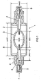
- a metal halide lamp 1 sealed by fuses 2 is shown. It is a 150 W lamp with a discharge vessel 3.
- the melts have initially a diameter of 5 mm, which widened at the level of the sealing foils 4 made of molybdenum to 7.3 mm.
- a base part 7 is integrated.
- the discharge vessel is surrounded by an outer bulb 8, which is designed substantially cylindrical. He narrows at the level of the film to a neck portion 9, which ends at the bead 6.
- the outer bulb has a length LAKO of 48 mm, the total length including the two neck parts is 72 mm.
- Such a compact lamp achieves a service life of at least 6000 hours, in particular even more than 9000 hours, with optimum design despite high load.
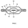
- FIG. 2 It shows the lateral view of a two-sided squeezed halogen incandescent lamp 10. It consists of an inner piston 11, in the center of which a luminous element 12 is arranged axially. The ends 13 of the filament are embedded in their function as an internal power supply directly into the pinch 14 and there connected to a pinch film 15.
- the outer bulb 16 is cylindrical with bevelled Ends 17, which together define the length LAKO here, and a neck portion 18 which abuts against the pinch 14.
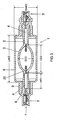
- FIG. 3 a metal halide lamp in which the discharge vessel 3 is shaped substantially like an ellipsoid, but has a wedge-shaped extension 20 at the end.
- LEG means the entire inside length of the discharge vessel.
Landscapes
- Vessels And Coating Films For Discharge Lamps (AREA)
- Discharge Lamps And Accessories Thereof (AREA)
Description
- Die Erfindung betrifft eine Elektrische Lampe mit Außenkolben gemäß dem Oberbegriff des Anspruchs 1. Es handelt sich dabei insbesondere um Metallhalogenidlampen, Quecksilber-Hochdruckentladungslampen, aber auch Halogenglühlampen mit Außenkolben. Der Innenkolben der Lampe ist mit Abdichtungsteilen zweiseitig verschlossen. Der Außenkolben ist an einer oder beiden Abdichtungsteilen befestigt.
- Aus der
EP-A 465 083 EP-A 588 602 - Aus der
EP 1 492 146 ist eine Lampe mit Außenkolben bekannt, die jedoch nicht für kompakte Leuchten eingesetzt werden kann. In derartigen Situationen ist die Temperaturbelastung der Lampe sehr hoch, so dass besondere konstruktive Maßnahmen ergriffen werden müssen. - Es ist Aufgabe der vorliegenden Erfindung, eine Lampe gemäß dem Oberbegriff des Anspruchs 1 bereitzustellen, die eine hohe Temperaturbelastung ertragen kann, und die insbesondere eine lange Lebensdauer gewährleistet. Durch eine kompakte Lampenform sind kleinere und kostengünstigere Leuchten möglich.
- Diese Aufgabe wird durch die kennzeichnenden Merkmale des Anspruchs 1 gelöst. Besonders vorteilhafte Ausgestaltungen finden sich in den abhängigen Ansprüchen.
- Die erfindungsgemäße Lampe besitzt ein vakuumdicht abgeschlossenen Innenkolben, insbesondere ein Entladungsgefäß, das eine Lampenachse definiert, und das an einander gegenüberliegenden Enden durch Abdichtungsteile verschlossen ist.
- Das Abdichtungsteil ist eine Quetschung oder auch Einschmelzung. Das Leuchtmittel im Innern der Lampe ist ein Entladungsbogen zwischen zwei Elektroden oder ein Leuchtkörper. Es ist mit den zu ihm führenden inneren Stromzuführungen elektrisch leitend verbunden. Das Abdichtungsteil ist insbesondere mit einer nach außen abstehenden Verlängerung versehen, die als hohles Rohr ausgebildet ist im folgenden wird der Begriff Entladungsgefäß für den Innenkolben beispielhaft ohne Einschränkung verwendet.
- Bisherige Versuche, kompakte Lampen der gattungsgemäßen Art zu schaffen, erzielten nur Lebensdauer von maximal 2000 Std., so daß derartige Lampen nur für fotooptische Anwendungen geeignet waren.
- Erfindungsgemäß wird ein besonderes Augenmerk auf die Regelung der Temperatur am äußeren Ende der Molybdänfolie in der Abdichtung des Entladungsgefäßes gelegt. Da das Entladungsgefäß nicht komplett von einem Außenkolben umschlossen ist, kommt diese Stelle mit Luft in Berührung. Das Molybdän kann oxidieren, was den Stromfluss unterbricht. Deshalb wird jetzt eine entscheidende Maßnahme ergriffen, nämlich die Verkürzung des Außenkolbens. Als Länge des Außenkolbens wird sein zentraler Teil verstanden, ohne etwaige an die Abdichtung angepasste Teile. Dabei hat sich als wesentlich herausgestellt, dass die derart definierte Länge des Außenkolbens, verglichen mit der Länge des Entladungsgefäßes, verstanden als Länge von dessen Innenvolumen, nur zwischen dem 1,3 und 4-fachen dieser Länge beträgt. Insbesondere ist ein Wert bevorzugt zwischen dem 1,5 und 3-fachen, besonders bevorzugt ist maximal ein Wert vom 2,5-fachen.
- Dabei soll insbesondere der Außenkolben möglichst eng am Entladungsgefäß anliegen. Ein günstiger Wert für das Verhältnis zwischen Durchmesser des Außenkolbens zu Durchmesser des Entladungsgefäßes ist 1,1 bis 2,5, bevorzugt liegt das Verhältnis zwischen 1,2 und 2,0.
- Ein weiterer wichtiges Orientierungsmerkmal ist die Länge des Außenkolbens (zylindrisches Teil) in Relation zur Lampenleistung. Dieses Verhältnis LW sollte zwischen 1,8 und 3,5 W/mm liegen. Ein konkretes Beispiel ist eine 75 W-Lampe mit einer Länge des Außenkolbens von 36 mm, so dass LW = 75W/36mm=2,08 W/mm. Bei einer 150 W-Lampe wird eine Länge des Außenkolbens von 48 mm verwendet, so dass hier gilt LW = 150W/48mm= 3,12 W/mm.
- Eine weitere vorteilhafte Maßnahme ist die Verlängerung der Mo-Folien. Dies sollte in Relation zur Länge des Außenkolbens geschehen. Eine hohe Temperaturbelastbarkeit wird insbesondere erzielt, wenn die gesamte Länge der beiden Mo-Folien des Entladungsgefäßes LMO zur Länge des Außenkolbens LAKO zwischen 0,4 und 1 liegt, Randwerte eingeschlossen, insbesondere mindestens 0,45. Bevorzugt ist LMO/LAKO zwischen 0,55 und 0,9. In aller Regel sind dabei beide Folien gleich lang, in speziellen Fällen kann es jedoch günstiger sein, die eine Folie länger als die andere zu machen. Ein konkretes Ausführungsbeispiel ist bei einer 150W-Lampe: 2X17mm/48mm= 0,7; bei einer 70W-Lampe: 2X12/36=0,66. Bei einer konventionellen Lampe beträgt dieses Verhältnis typisch zwischen 0,2 und 0,3.
- Eine weitere vorteilhafte Maßnahme ist das sog. Ziehen der Schäfte, das überraschend ebenfalls das Ziel unterstützt, die Temperatur am Ende der Mo-Folie abzusenken. Dabei ist im Falle einer Einschmelzung diese im Übergang vom Innenkolben zum Schaft durch Ziehen verdünnt und wird zum Schaftende wieder dicker. Bevorzugt wird er um 20 bis 60 % dicker. Der Schaft hat konkret an der dünnen Stelle nach dem Innenkolben bei moderater Leistung, typisch 70 bis 150 W, einen Durchmesser von etwa 5 mm und an der Stelle, wo der Außenkolben aufgerollt ist, einen Durchmesser von 7 bis 8 mm.
- Bevorzugt ist mindestens ein Abdichtungsteil mit einem, insbesondere ringförmigen, Wulst versehen, der quer zu Lampenachse radial absteht. Eine derartige Gestalt des Wulstes kann entweder nach lokalem Erwärmen durch Stauchen oder Aufblasen erzeugt werden. Noch einfacher ist das Aufbringen einer entsprechend geformten Glasperle.
- Der Außenkolben kann ein durchgehendes Rohrstück mit gleichbleibendem Durchmesser sein, aber auch ein Kolben mit zentralem Bauch und endständig daran angrenzenden, insbesondere angesetzten oder angeformten, Rohrstücken.
- Eine bevorzugte Ausführungsform sieht ein rohrförmiges Verlängerungsstück des Abdichtungsteils vor, an dem der Wulst angrenzt. Er ist insbesondere angesetzt oder angeformt. Dadurch ist auch bei einer nicht radialsymmetrischen Quetschung die Bereitstellung eines radialsymmetrischen Wulstes möglich. Bei einer Einschmelzung ist ein derartiges Verlängerungsstück nicht unbedingt notwendig. Bevorzugt sind sowohl Innenkolben als auch Außenkolben aus Quarzglas, evtl. auch aus Hartglas.
- Im folgenden soll die Erfindung anhand mehrerer Ausführungsbeispiele näher erläutert werden. Es zeigen:
- Figur 1
- ein Ausführungsbeispiel einer Metallhalogenidlampe in Seitenansicht;
- Figur 2 ;
- eine Halogenglühlampe in Seitenansicht;
- Figur 3
- eine weiteres Ausführungsbeispiel einer Metallhalogenidlampe.
- In
Figur 1 ist eine Metallhalogenidlampe 1 gezeigt, die durch Einschmelzungen 2 abgedichtet ist. Es handelt sich um eine 150 W Lampe mit einem Entladungsgefäß 3. Die Einschmelzungen haben anfangs einen Durchmesser von 5 mm, der sich in Höhe der Einschmelzfolien 4 aus Molybdän auf 7,3 mm verbreitert. Die Folien sind jeweils 17 mm lang, also ist LMO = 34 mm. Am Ende der Einschmelzung setzt ein kurzes Rohrstück 5 integral an, das mit einem Wulst 6 ausgestattet ist. Im Rohrstück ist ein Sockelteil 7 integriert. - Das Entladungsgefäß ist von einem Außenkolben 8 umgeben, der im wesentlichen zylindrisch gestaltet ist. Er verengt sich in Höhe der Folie zu einem Halsteil 9, das an dem Wulst 6 endet. Der Außenkolben hat eine Länge LAKO von 48 mm, die Gesamtlänge incl. der beiden Halsteile ist 72 mm.
- Eine derart kompakte Lampe erreicht trotz hoher Belastung eine Lebensdauer von mindestens 6000 Std., insbesondere sogar mehr als 9000 Std. bei optimaler Gestaltung.
-
Figur 2 zeigt die seitliche Ansicht einer zweiseitig gequetschten Halogenglühlampe 10. Sie besteht aus einem inneren Kolben 11, in dessen Zentrum ein Leuchtkörper 12 axial angeordnet ist. Die Enden 13 des Leuchtkörpers sind in ihrer Funktion als innere Stromzuführung direkt in die Quetschung 14 eingebettet und dort mit einer Quetschfolie 15 verbunden. Der Außenkolben 16 ist zylindrisch mit abgeschrägten Enden 17, die zusammen die Länge LAKO hier definieren, und einem Halsteil 18, das an der Quetschung 14 anliegt. - Konkrete Bemaßungen sind in der folgenden Tabelle angegeben für Metallhalogenidlampen mit 70 und 150 W Leistung. Sie können auch für Halogenglühlampen als Anhaltspunkt der Bemaßung dienen. Dabei kann die Bemaßung der Metallhalogenidlampen unabhängig von der Lichtfarbe verwendet werden, beispielsweise für warmweiß und neutralweiß.
Tab. 1 Leistung 75 W 150 W Mittlere Lebensdauer (h) 9000 9000 Elektrodenabstand (mm) 9 15 Durchmesser Innenkolben (in mm) 11 14,9 Länge Innenkolben (in mm) 16,7 24,7 Durchmesser Außenkolben (in mm) 18,8 22,3 Länge LAKO des Außenkolbens (in mm) 36 48 Lampenlänge gesamt (in mm) 77 95 - Schließlich zeigt
Figur 3 eine Metallhalogenidlampe, bei der das Entladungsgefäß 3 zwar im wesentlichen wie ein Ellipsoid geformt ist, jedoch eine keilförmige Verlängerung 20 am Ende aufweist. Auch hier ist mit LEG die gesamte Innenlänge des Entladungsgefäßes gemeint.
Claims (6)
- Elektrische Lampe mit Außenkolben mit einem vakuumdicht abgeschlossenen, längsgestreckten Innenkolben (1), der eine Längsachse (A) und eine Innenlänge LEG definiert, und der ein Leuchtmittel enthält, und der an zwei einander gegenüberliegenden Enden durch Abdichtungsteile (6; 32) verschlossen ist, wobei ein Außenkolben mit einer Gesamtlänge LAKO und mit zwei Halsteilen dem Innenkolben übergestülpt ist und wobei die Halsteile an den Abdichtungsteilen befestigt sind wobei die Abdichtungsteile Folien enthalten, dadurch gekennzeichnet, dass das Verhältnis zwischen der Gesamtlänge des Außenkolbens LAKO und der Innenlänge des Innenvolumens LEG zwischen 1,3 und 4, bevorzugt 1,5 und 3, liegt.
- Lampe nach Anspruch 1, dadurch gekennzeichnet, dass der Innenkolben einen maximalen Durchmesser DEG und der Außenkolben einen maximalen Durchmesser DAKO besitzt, wobei das Verhältnis DAKO/DEG zwischen 1,1 und 2,5, bevorzugt zwischen 1,2 und 2.0 liegt.
- Lampe nach Anspruch 1, dadurch gekennzeichnet, dass die Länge des Außenkolbens LAKO (in mm) auf die Nennleistung P (in W) der Lampe abgestimmt ist, so dass das Verhältnis P/LAKO zwischen 1,8 und 3,5 W/mm liegt.
- Lampe nach Anspruch 1, dadurch gekennzeichnet, dass die Länge der beiden Folien LMO, auf die Länge des Außenkolbens LAKO abgestimmt ist, so dass das Verhältnis LMO/LAKO zwischen 0,4 und 1,0 beträgt, insbesondere zwischen 0,55 und 0,9.
- Lampe nach Anspruch 1, dadurch gekennzeichnet, dass die Abdichtungen als Einschmelzungen ausgeführt sind, wobei der Durchmesser der Einschmelzung sich von innen nach außen vergrößert.
- Lampe nach Anspruch 5, dadurch gekennzeichnet, dass der Durchmesser in Höhe des entladungsfernen Endes der Folie zwischen 120 und 160 % des Durchmessers in der Nähe des Innenvolumens ausmacht.
Applications Claiming Priority (1)
| Application Number | Priority Date | Filing Date | Title |
|---|---|---|---|
| DE102005020344A DE102005020344A1 (de) | 2005-05-02 | 2005-05-02 | Elektrische Lampe mit Außenkolben |
Publications (2)
| Publication Number | Publication Date |
|---|---|
| EP1720189A1 EP1720189A1 (de) | 2006-11-08 |
| EP1720189B1 true EP1720189B1 (de) | 2008-08-13 |
Family
ID=36808884
Family Applications (1)
| Application Number | Title | Priority Date | Filing Date |
|---|---|---|---|
| EP06008317A Expired - Lifetime EP1720189B1 (de) | 2005-05-02 | 2006-04-21 | Doppelwandige elektrische Lampe |
Country Status (7)
| Country | Link |
|---|---|
| US (1) | US7514873B2 (de) |
| EP (1) | EP1720189B1 (de) |
| JP (1) | JP2006313749A (de) |
| CN (1) | CN1881524B (de) |
| AT (1) | ATE404988T1 (de) |
| CA (1) | CA2545378A1 (de) |
| DE (2) | DE102005020344A1 (de) |
Families Citing this family (3)
| Publication number | Priority date | Publication date | Assignee | Title |
|---|---|---|---|---|
| CN101636816B (zh) * | 2007-03-12 | 2011-09-14 | 皇家飞利浦电子股份有限公司 | 具有高效能的低功率放电灯 |
| EP1975975A1 (de) * | 2007-03-30 | 2008-10-01 | Patent-Treuhand-Gesellschaft Für Elektrische Glühlampen mbH | Baueinheit für eine elektrische Lampe mit Aussenkolben |
| KR100918430B1 (ko) | 2007-11-22 | 2009-09-24 | 조정열 | 이중관 구조의 램프 제조 방법 |
Family Cites Families (15)
| Publication number | Priority date | Publication date | Assignee | Title |
|---|---|---|---|---|
| DE3878367T2 (de) * | 1987-09-24 | 1993-07-29 | Philips Nv | Scheinwerferanlage und elektrische lampe dafuer. |
| US4935668A (en) * | 1988-02-18 | 1990-06-19 | General Electric Company | Metal halide lamp having vacuum shroud for improved performance |
| US4945288A (en) * | 1988-12-21 | 1990-07-31 | Gte Products Corporation | Double jacket lamp |
| CA2042143A1 (en) | 1990-06-27 | 1991-12-28 | John J. Biel | Discharge lamp with surrounding shroud and method of making such lamp |
| EP0533325B1 (de) * | 1991-07-25 | 1996-01-10 | Hamamatsu Photonics K.K. | Entladungsröhre |
| JPH05343031A (ja) * | 1992-06-04 | 1993-12-24 | Hamamatsu Photonics Kk | 放電管とその製造方法 |
| US5253153A (en) * | 1992-09-16 | 1993-10-12 | General Electric Company | Vehicle headlamp comprising a metal-halide discharge lamp including an inner envelope and a surrounding shroud |
| JP3777034B2 (ja) * | 1997-12-11 | 2006-05-24 | 株式会社小糸製作所 | 放電ランプ装置用絶縁プラグ |
| DE69900804T3 (de) * | 1998-06-12 | 2007-07-12 | Matsushita Electric Industrial Co., Ltd., Kadoma | Entladungslampe |
| JP3916887B2 (ja) * | 2001-06-05 | 2007-05-23 | 株式会社小糸製作所 | 照明装置 |
| JP2004172056A (ja) * | 2002-11-22 | 2004-06-17 | Koito Mfg Co Ltd | 放電ランプ装置用水銀フリーアークチューブ |
| JP2004253362A (ja) * | 2002-12-24 | 2004-09-09 | Toshiba Lighting & Technology Corp | 高圧放電ランプおよび照明装置 |
| DE10325552A1 (de) * | 2003-06-05 | 2004-12-23 | Patent-Treuhand-Gesellschaft für elektrische Glühlampen mbH | Elektrische Lampe mit Außenkolben und zugehöriger Trägerkörper |
| DE10325554A1 (de) * | 2003-06-05 | 2004-12-23 | Patent-Treuhand-Gesellschaft für elektrische Glühlampen mbH | Verfahren zur Herstellung einer elektrischen Lampe mit Außenkolben |
| DE102004005903A1 (de) * | 2004-02-05 | 2005-08-25 | Patent-Treuhand-Gesellschaft für elektrische Glühlampen mbH | Hochdruckentladungslampe und Herstellungsverfahren für eine Hochdruckentladungslampe |
-
2005
- 2005-05-02 DE DE102005020344A patent/DE102005020344A1/de not_active Withdrawn
-
2006
- 2006-04-21 EP EP06008317A patent/EP1720189B1/de not_active Expired - Lifetime
- 2006-04-21 DE DE502006001302T patent/DE502006001302D1/de not_active Expired - Lifetime
- 2006-04-21 AT AT06008317T patent/ATE404988T1/de not_active IP Right Cessation
- 2006-04-28 CA CA002545378A patent/CA2545378A1/en not_active Abandoned
- 2006-04-29 CN CN2006100886516A patent/CN1881524B/zh not_active Expired - Fee Related
- 2006-05-01 US US11/414,388 patent/US7514873B2/en not_active Expired - Fee Related
- 2006-05-01 JP JP2006127599A patent/JP2006313749A/ja active Pending
Also Published As
| Publication number | Publication date |
|---|---|
| US20060244384A1 (en) | 2006-11-02 |
| DE502006001302D1 (de) | 2008-09-25 |
| EP1720189A1 (de) | 2006-11-08 |
| US7514873B2 (en) | 2009-04-07 |
| CA2545378A1 (en) | 2006-11-02 |
| CN1881524A (zh) | 2006-12-20 |
| JP2006313749A (ja) | 2006-11-16 |
| DE102005020344A1 (de) | 2006-11-09 |
| CN1881524B (zh) | 2011-05-18 |
| ATE404988T1 (de) | 2008-08-15 |
Similar Documents
| Publication | Publication Date | Title |
|---|---|---|
| EP0839381B1 (de) | Reflektorlampe | |
| EP0602530A2 (de) | Verfahren zur Herstellung einer vakuumdichten Abdichtung zwischen einem keramischen und einem metallischen Partner, insbesondere für Entladungsgefässe und -lampen | |
| EP1720189B1 (de) | Doppelwandige elektrische Lampe | |
| EP0825636B1 (de) | Hochdruckentladungslampe | |
| EP0591777A2 (de) | Verfahren zur Herstellung einer einseitig gequetschten Hochdruckentladungslampe kleiner Leistung und Hochdruckentladungslampen | |
| EP0061757B1 (de) | Verfahren zur Herstellung einer als Quetschung ausgebildeten Gefässabdichtung für eine elektrische Lampe und Quetschvorrichtung zum Durchführen des Verfahrens | |
| WO2010060699A1 (de) | Halogenglühlampe für den betrieb an netzspannung | |
| EP0987737A1 (de) | Leuchtstofflampe | |
| EP0446461B1 (de) | Einseitig gequetschte Halogen-Glühlampe | |
| EP1709668B1 (de) | Niederdruckentladungslampe | |
| EP1911065B1 (de) | ELEKTRISCHE LAMPE MIT AUßENKOLBEN | |
| WO2008006759A2 (de) | Hochdruckentladungslampe | |
| DE102010038403A1 (de) | Hochdruckentladungslampe mit Zündhilfe | |
| EP1665318A2 (de) | Zweiseitig verschlossene elektrische lampe und verfahren zu deren herstellung | |
| DE19633732A1 (de) | Hochdruckentladungslampe | |
| DE102009015894A1 (de) | Elektrische Lampe | |
| DE3321479A1 (de) | Hochdruckentladungslampe | |
| DE102004056452A1 (de) | Elektrische Lampe mit Außenkolben | |
| DE102009055137A1 (de) | Hochdruckentladungslampe | |
| DE102011006708A1 (de) | Entladungslampe, insbesondere Quecksilber-Niederdruckentladungslampe | |
| DE202007011210U1 (de) | Baueinheit für eine elektrische Lampe mit Außenkolben | |
| DE102004044364A1 (de) | Glühlampe | |
| WO2008119623A1 (de) | Baueinheit für eine elektrische lampe mit aussenkolben | |
| EP2370986A1 (de) | ELEKTRISCHE LAMPE MIT AUßENKOLBEN | |
| DE102011006700A1 (de) | Entladungslampe, insbesondere Quecksilber-Niederdruckentladungslampe, sowie Verfahren zum Herstellen einer Entladungslampe |
Legal Events
| Date | Code | Title | Description |
|---|---|---|---|
| PUAI | Public reference made under article 153(3) epc to a published international application that has entered the european phase |
Free format text: ORIGINAL CODE: 0009012 |
|
| AK | Designated contracting states |
Kind code of ref document: A1 Designated state(s): AT BE BG CH CY CZ DE DK EE ES FI FR GB GR HU IE IS IT LI LT LU LV MC NL PL PT RO SE SI SK TR |
|
| AX | Request for extension of the european patent |
Extension state: AL BA HR MK YU |
|
| 17P | Request for examination filed |
Effective date: 20061107 |
|
| AKX | Designation fees paid |
Designated state(s): AT BE BG CH CY CZ DE DK EE ES FI FR GB GR HU IE IS IT LI LT LU LV MC NL PL PT RO SE SI SK TR |
|
| GRAP | Despatch of communication of intention to grant a patent |
Free format text: ORIGINAL CODE: EPIDOSNIGR1 |
|
| GRAS | Grant fee paid |
Free format text: ORIGINAL CODE: EPIDOSNIGR3 |
|
| GRAA | (expected) grant |
Free format text: ORIGINAL CODE: 0009210 |
|
| AK | Designated contracting states |
Kind code of ref document: B1 Designated state(s): AT BE BG CH CY CZ DE DK EE ES FI FR GB GR HU IE IS IT LI LT LU LV MC NL PL PT RO SE SI SK TR |
|
| REG | Reference to a national code |
Ref country code: GB Ref legal event code: FG4D Free format text: NOT ENGLISH |
|
| REG | Reference to a national code |
Ref country code: CH Ref legal event code: EP |
|
| REG | Reference to a national code |
Ref country code: IE Ref legal event code: FG4D Free format text: LANGUAGE OF EP DOCUMENT: GERMAN |
|
| REF | Corresponds to: |
Ref document number: 502006001302 Country of ref document: DE Date of ref document: 20080925 Kind code of ref document: P |
|
| PG25 | Lapsed in a contracting state [announced via postgrant information from national office to epo] |
Ref country code: LT Free format text: LAPSE BECAUSE OF FAILURE TO SUBMIT A TRANSLATION OF THE DESCRIPTION OR TO PAY THE FEE WITHIN THE PRESCRIBED TIME-LIMIT Effective date: 20080813 Ref country code: IS Free format text: LAPSE BECAUSE OF FAILURE TO SUBMIT A TRANSLATION OF THE DESCRIPTION OR TO PAY THE FEE WITHIN THE PRESCRIBED TIME-LIMIT Effective date: 20081213 |
|
| PG25 | Lapsed in a contracting state [announced via postgrant information from national office to epo] |
Ref country code: SI Free format text: LAPSE BECAUSE OF FAILURE TO SUBMIT A TRANSLATION OF THE DESCRIPTION OR TO PAY THE FEE WITHIN THE PRESCRIBED TIME-LIMIT Effective date: 20080813 Ref country code: FI Free format text: LAPSE BECAUSE OF FAILURE TO SUBMIT A TRANSLATION OF THE DESCRIPTION OR TO PAY THE FEE WITHIN THE PRESCRIBED TIME-LIMIT Effective date: 20080813 Ref country code: LV Free format text: LAPSE BECAUSE OF FAILURE TO SUBMIT A TRANSLATION OF THE DESCRIPTION OR TO PAY THE FEE WITHIN THE PRESCRIBED TIME-LIMIT Effective date: 20080813 Ref country code: ES Free format text: LAPSE BECAUSE OF FAILURE TO SUBMIT A TRANSLATION OF THE DESCRIPTION OR TO PAY THE FEE WITHIN THE PRESCRIBED TIME-LIMIT Effective date: 20081124 |
|
| REG | Reference to a national code |
Ref country code: HU Ref legal event code: AG4A Ref document number: E004252 Country of ref document: HU |
|
| REG | Reference to a national code |
Ref country code: IE Ref legal event code: FD4D |
|
| PG25 | Lapsed in a contracting state [announced via postgrant information from national office to epo] |
Ref country code: BG Free format text: LAPSE BECAUSE OF FAILURE TO SUBMIT A TRANSLATION OF THE DESCRIPTION OR TO PAY THE FEE WITHIN THE PRESCRIBED TIME-LIMIT Effective date: 20081113 Ref country code: DK Free format text: LAPSE BECAUSE OF FAILURE TO SUBMIT A TRANSLATION OF THE DESCRIPTION OR TO PAY THE FEE WITHIN THE PRESCRIBED TIME-LIMIT Effective date: 20080813 Ref country code: IE Free format text: LAPSE BECAUSE OF FAILURE TO SUBMIT A TRANSLATION OF THE DESCRIPTION OR TO PAY THE FEE WITHIN THE PRESCRIBED TIME-LIMIT Effective date: 20080813 |
|
| PG25 | Lapsed in a contracting state [announced via postgrant information from national office to epo] |
Ref country code: RO Free format text: LAPSE BECAUSE OF FAILURE TO SUBMIT A TRANSLATION OF THE DESCRIPTION OR TO PAY THE FEE WITHIN THE PRESCRIBED TIME-LIMIT Effective date: 20080813 Ref country code: PT Free format text: LAPSE BECAUSE OF FAILURE TO SUBMIT A TRANSLATION OF THE DESCRIPTION OR TO PAY THE FEE WITHIN THE PRESCRIBED TIME-LIMIT Effective date: 20090113 Ref country code: CZ Free format text: LAPSE BECAUSE OF FAILURE TO SUBMIT A TRANSLATION OF THE DESCRIPTION OR TO PAY THE FEE WITHIN THE PRESCRIBED TIME-LIMIT Effective date: 20080813 Ref country code: SK Free format text: LAPSE BECAUSE OF FAILURE TO SUBMIT A TRANSLATION OF THE DESCRIPTION OR TO PAY THE FEE WITHIN THE PRESCRIBED TIME-LIMIT Effective date: 20080813 |
|
| PLBE | No opposition filed within time limit |
Free format text: ORIGINAL CODE: 0009261 |
|
| STAA | Information on the status of an ep patent application or granted ep patent |
Free format text: STATUS: NO OPPOSITION FILED WITHIN TIME LIMIT |
|
| 26N | No opposition filed |
Effective date: 20090514 |
|
| PG25 | Lapsed in a contracting state [announced via postgrant information from national office to epo] |
Ref country code: EE Free format text: LAPSE BECAUSE OF FAILURE TO SUBMIT A TRANSLATION OF THE DESCRIPTION OR TO PAY THE FEE WITHIN THE PRESCRIBED TIME-LIMIT Effective date: 20080813 |
|
| PG25 | Lapsed in a contracting state [announced via postgrant information from national office to epo] |
Ref country code: IT Free format text: LAPSE BECAUSE OF FAILURE TO SUBMIT A TRANSLATION OF THE DESCRIPTION OR TO PAY THE FEE WITHIN THE PRESCRIBED TIME-LIMIT Effective date: 20080813 |
|
| PG25 | Lapsed in a contracting state [announced via postgrant information from national office to epo] |
Ref country code: SE Free format text: LAPSE BECAUSE OF FAILURE TO SUBMIT A TRANSLATION OF THE DESCRIPTION OR TO PAY THE FEE WITHIN THE PRESCRIBED TIME-LIMIT Effective date: 20081113 |
|
| PG25 | Lapsed in a contracting state [announced via postgrant information from national office to epo] |
Ref country code: MC Free format text: LAPSE BECAUSE OF NON-PAYMENT OF DUE FEES Effective date: 20090430 |
|
| PG25 | Lapsed in a contracting state [announced via postgrant information from national office to epo] |
Ref country code: PL Free format text: LAPSE BECAUSE OF FAILURE TO SUBMIT A TRANSLATION OF THE DESCRIPTION OR TO PAY THE FEE WITHIN THE PRESCRIBED TIME-LIMIT Effective date: 20080813 |
|
| PG25 | Lapsed in a contracting state [announced via postgrant information from national office to epo] |
Ref country code: AT Free format text: LAPSE BECAUSE OF NON-PAYMENT OF DUE FEES Effective date: 20090421 |
|
| PG25 | Lapsed in a contracting state [announced via postgrant information from national office to epo] |
Ref country code: GR Free format text: LAPSE BECAUSE OF FAILURE TO SUBMIT A TRANSLATION OF THE DESCRIPTION OR TO PAY THE FEE WITHIN THE PRESCRIBED TIME-LIMIT Effective date: 20081114 |
|
| REG | Reference to a national code |
Ref country code: CH Ref legal event code: PL |
|
| PG25 | Lapsed in a contracting state [announced via postgrant information from national office to epo] |
Ref country code: CH Free format text: LAPSE BECAUSE OF NON-PAYMENT OF DUE FEES Effective date: 20100430 Ref country code: LI Free format text: LAPSE BECAUSE OF NON-PAYMENT OF DUE FEES Effective date: 20100430 |
|
| PG25 | Lapsed in a contracting state [announced via postgrant information from national office to epo] |
Ref country code: LU Free format text: LAPSE BECAUSE OF NON-PAYMENT OF DUE FEES Effective date: 20090421 |
|
| PGFP | Annual fee paid to national office [announced via postgrant information from national office to epo] |
Ref country code: FR Payment date: 20110427 Year of fee payment: 6 |
|
| PG25 | Lapsed in a contracting state [announced via postgrant information from national office to epo] |
Ref country code: TR Free format text: LAPSE BECAUSE OF FAILURE TO SUBMIT A TRANSLATION OF THE DESCRIPTION OR TO PAY THE FEE WITHIN THE PRESCRIBED TIME-LIMIT Effective date: 20080813 |
|
| PGFP | Annual fee paid to national office [announced via postgrant information from national office to epo] |
Ref country code: GB Payment date: 20110414 Year of fee payment: 6 |
|
| PG25 | Lapsed in a contracting state [announced via postgrant information from national office to epo] |
Ref country code: CY Free format text: LAPSE BECAUSE OF FAILURE TO SUBMIT A TRANSLATION OF THE DESCRIPTION OR TO PAY THE FEE WITHIN THE PRESCRIBED TIME-LIMIT Effective date: 20080813 |
|
| REG | Reference to a national code |
Ref country code: DE Ref legal event code: R081 Ref document number: 502006001302 Country of ref document: DE Owner name: OSRAM GMBH, DE Free format text: FORMER OWNER: OSRAM GESELLSCHAFT MIT BESCHRAENKTER HAFTUNG, 81543 MUENCHEN, DE Effective date: 20111213 Ref country code: DE Ref legal event code: R081 Ref document number: 502006001302 Country of ref document: DE Owner name: LEDVANCE GMBH, DE Free format text: FORMER OWNER: OSRAM GESELLSCHAFT MIT BESCHRAENKTER HAFTUNG, 81543 MUENCHEN, DE Effective date: 20111213 |
|
| PGFP | Annual fee paid to national office [announced via postgrant information from national office to epo] |
Ref country code: HU Payment date: 20120614 Year of fee payment: 7 Ref country code: NL Payment date: 20120418 Year of fee payment: 7 |
|
| PGFP | Annual fee paid to national office [announced via postgrant information from national office to epo] |
Ref country code: BE Payment date: 20120510 Year of fee payment: 7 |
|
| GBPC | Gb: european patent ceased through non-payment of renewal fee |
Effective date: 20120421 |
|
| REG | Reference to a national code |
Ref country code: FR Ref legal event code: ST Effective date: 20121228 |
|
| PG25 | Lapsed in a contracting state [announced via postgrant information from national office to epo] |
Ref country code: GB Free format text: LAPSE BECAUSE OF NON-PAYMENT OF DUE FEES Effective date: 20120421 |
|
| PG25 | Lapsed in a contracting state [announced via postgrant information from national office to epo] |
Ref country code: FR Free format text: LAPSE BECAUSE OF NON-PAYMENT OF DUE FEES Effective date: 20120430 |
|
| REG | Reference to a national code |
Ref country code: DE Ref legal event code: R081 Ref document number: 502006001302 Country of ref document: DE Owner name: OSRAM GMBH, DE Free format text: FORMER OWNER: OSRAM AG, 81543 MUENCHEN, DE Effective date: 20130205 Ref country code: DE Ref legal event code: R081 Ref document number: 502006001302 Country of ref document: DE Owner name: LEDVANCE GMBH, DE Free format text: FORMER OWNER: OSRAM AG, 81543 MUENCHEN, DE Effective date: 20130205 |
|
| REG | Reference to a national code |
Ref country code: DE Ref legal event code: R081 Ref document number: 502006001302 Country of ref document: DE Owner name: OSRAM GMBH, DE Free format text: FORMER OWNER: OSRAM GMBH, 81543 MUENCHEN, DE Effective date: 20130823 Ref country code: DE Ref legal event code: R081 Ref document number: 502006001302 Country of ref document: DE Owner name: LEDVANCE GMBH, DE Free format text: FORMER OWNER: OSRAM GMBH, 81543 MUENCHEN, DE Effective date: 20130823 |
|
| BERE | Be: lapsed |
Owner name: PATENT-TREUHAND-GESELLSCHAFT FUR ELEKTRISCHE GLUH Effective date: 20130430 |
|
| REG | Reference to a national code |
Ref country code: NL Ref legal event code: V1 Effective date: 20131101 |
|
| PG25 | Lapsed in a contracting state [announced via postgrant information from national office to epo] |
Ref country code: BE Free format text: LAPSE BECAUSE OF NON-PAYMENT OF DUE FEES Effective date: 20130430 |
|
| PG25 | Lapsed in a contracting state [announced via postgrant information from national office to epo] |
Ref country code: NL Free format text: LAPSE BECAUSE OF NON-PAYMENT OF DUE FEES Effective date: 20131101 Ref country code: HU Free format text: LAPSE BECAUSE OF NON-PAYMENT OF DUE FEES Effective date: 20130422 |
|
| REG | Reference to a national code |
Ref country code: DE Ref legal event code: R081 Ref document number: 502006001302 Country of ref document: DE Owner name: LEDVANCE GMBH, DE Free format text: FORMER OWNER: OSRAM GMBH, 80807 MUENCHEN, DE |
|
| PGFP | Annual fee paid to national office [announced via postgrant information from national office to epo] |
Ref country code: DE Payment date: 20170630 Year of fee payment: 12 |
|
| REG | Reference to a national code |
Ref country code: DE Ref legal event code: R119 Ref document number: 502006001302 Country of ref document: DE |
|
| PG25 | Lapsed in a contracting state [announced via postgrant information from national office to epo] |
Ref country code: DE Free format text: LAPSE BECAUSE OF NON-PAYMENT OF DUE FEES Effective date: 20181101 |