EP1720241A2 - Photovoltaikgenerator mit Thermoschaltelement - Google Patents
Photovoltaikgenerator mit Thermoschaltelement Download PDFInfo
- Publication number
- EP1720241A2 EP1720241A2 EP20060006480 EP06006480A EP1720241A2 EP 1720241 A2 EP1720241 A2 EP 1720241A2 EP 20060006480 EP20060006480 EP 20060006480 EP 06006480 A EP06006480 A EP 06006480A EP 1720241 A2 EP1720241 A2 EP 1720241A2
- Authority
- EP
- European Patent Office
- Prior art keywords
- photovoltaic
- thermal switch
- photovoltaic generator
- module
- strand
- Prior art date
- Legal status (The legal status is an assumption and is not a legal conclusion. Google has not performed a legal analysis and makes no representation as to the accuracy of the status listed.)
- Withdrawn
Links
- 230000009467 reduction Effects 0.000 claims abstract description 15
- 230000004044 response Effects 0.000 claims description 9
- 238000004519 manufacturing process Methods 0.000 claims description 4
- 230000009471 action Effects 0.000 claims description 3
- 238000011156 evaluation Methods 0.000 claims description 3
- 238000009434 installation Methods 0.000 claims description 3
- XLYOFNOQVPJJNP-UHFFFAOYSA-N water Substances O XLYOFNOQVPJJNP-UHFFFAOYSA-N 0.000 description 3
- 238000006243 chemical reaction Methods 0.000 description 2
- 230000005611 electricity Effects 0.000 description 2
- 239000000779 smoke Substances 0.000 description 2
- 238000013459 approach Methods 0.000 description 1
- 230000015572 biosynthetic process Effects 0.000 description 1
- 230000003750 conditioning effect Effects 0.000 description 1
- 238000001514 detection method Methods 0.000 description 1
- 230000000694 effects Effects 0.000 description 1
- 239000006260 foam Substances 0.000 description 1
- 230000008821 health effect Effects 0.000 description 1
- 230000010354 integration Effects 0.000 description 1
- 230000001960 triggered effect Effects 0.000 description 1
Images


Classifications
-
- H—ELECTRICITY
- H02—GENERATION; CONVERSION OR DISTRIBUTION OF ELECTRIC POWER
- H02S—GENERATION OF ELECTRIC POWER BY CONVERSION OF INFRARED RADIATION, VISIBLE LIGHT OR ULTRAVIOLET LIGHT, e.g. USING PHOTOVOLTAIC [PV] MODULES
- H02S99/00—Subject matter not provided for in other groups of this subclass
-
- H—ELECTRICITY
- H10—SEMICONDUCTOR DEVICES; ELECTRIC SOLID-STATE DEVICES NOT OTHERWISE PROVIDED FOR
- H10F—INORGANIC SEMICONDUCTOR DEVICES SENSITIVE TO INFRARED RADIATION, LIGHT, ELECTROMAGNETIC RADIATION OF SHORTER WAVELENGTH OR CORPUSCULAR RADIATION
- H10F77/00—Constructional details of devices covered by this subclass
- H10F77/95—Circuit arrangements
- H10F77/953—Circuit arrangements for devices having potential barriers
- H10F77/955—Circuit arrangements for devices having potential barriers for photovoltaic devices
-
- Y—GENERAL TAGGING OF NEW TECHNOLOGICAL DEVELOPMENTS; GENERAL TAGGING OF CROSS-SECTIONAL TECHNOLOGIES SPANNING OVER SEVERAL SECTIONS OF THE IPC; TECHNICAL SUBJECTS COVERED BY FORMER USPC CROSS-REFERENCE ART COLLECTIONS [XRACs] AND DIGESTS
- Y02—TECHNOLOGIES OR APPLICATIONS FOR MITIGATION OR ADAPTATION AGAINST CLIMATE CHANGE
- Y02E—REDUCTION OF GREENHOUSE GAS [GHG] EMISSIONS, RELATED TO ENERGY GENERATION, TRANSMISSION OR DISTRIBUTION
- Y02E10/00—Energy generation through renewable energy sources
- Y02E10/50—Photovoltaic [PV] energy
Definitions
- Photovoltaic systems are well known. They are becoming increasingly important, especially in countries that provide for state support.
- the present invention is less concerned with large-scale installations erected on an open field than with smaller installations in the range of several kW of electrical power, which are mounted on building roofs.
- the invention is based on the consideration that even residential buildings and commercial buildings with photovoltaic systems are not immune to fire, and that they should be transferred in a fire in a safe for the firefighter state.
- Photovoltaic systems usually comprise several photovoltaic modules (hereinafter referred to as modules), which are arranged in series and thereby combined into one strand. Several of these strands are arranged parallel to one another and thus form a photovoltaic system. To use the solar power obtained, an inverter is connected in parallel with the strings, which converts the direct current into alternating current. In the sense of the above definition of the term "photovoltaic generator", the inverter does not belong to the photovoltaic generator itself.
- a single photovoltaic module comprises a plurality of photovoltaic cells connected in series (referred to below as cells for short), each of which single delivers about 2.5 watts according to current technology, ie, for example, at a voltage of 0.5 volts provides a current of 5 amperes. If a photovoltaic module contains, for example, 120 such cells, a direct voltage of 60 volts is applied to the connecting poles of the module. If, for example, eight of these modules are combined in series to form one strand, a voltage of approximately 480 volts is present between the ends of the strand.
- the invention has therefore set itself the task of a photovoltaic generator in case of fire in one for a deleting, e.g. to convict a firefighter to operate safely.
- thermal switch which causes a reduction in the power of the photovoltaic generator when responding, this reduction can go down to zero.
- a reduction in the power of the generator is due to the structure of photovoltaic systems always connected to a reduction in the voltage at least parts of the system.
- the thermal switch on the module itself e.g. constructive on its back, be provided. But he can also short a whole strand and thus disconnect power, or he can switch the entire system voltage. The reduction of the voltage leads to a reduced risk potential.
- a first advantageous basic embodiment thus relates to a photovoltaic generator with a plurality of series-connected photovoltaic cells, which together form a photovoltaic module, in which there are two electrical module connection poles at the ends of the row, and in which the thermal switch short-circuits the module connection poles during the response, thus causing a reduction in the power of the photovoltaic generator.
- a further advantageous basic embodiment thus relates to a photovoltaic generator with a string of photovoltaic modules connected electrically in series, an electrical strand connection pole being provided at both ends of the strand, and a thermal switch short-circuiting the two strand connection poles during the response and thus a reduction in the performance of the photovoltaic generator causes.
- a third advantageous basic embodiment thus relates to a photovoltaic generator with a plurality of electrically parallel-connected strings of series-connected photovoltaic modules and with a parallel to the strings inverter with two DC input terminals, a thermal switch in response short-circuiting the DC poles with each other and thus a reduction in the performance of the photovoltaic generator causes.
- thermal switch is here understood to mean any switching element which, upon reaching a predefinable or predetermined temperature or other fire-indicating parameter, initiates a switching operation which leads, indirectly or directly, to closing or opening an electrical connection.
- This parameter can be the appearance of smoke, the visibility through air, the ionization of air, the CO content, etc. It may be a thermal switch with a mechanical action principle, such as a bimetallic element, act. But it may also be a thermal switch with an electrical or electronic action principle, such as a temperature sensor to which an evaluation circuit is connected or incorporated, act. Instead, a smoke detector (eg located on the back of the module) or a standard fire detector can be used on the ceiling of a room in the building in question. The switching operation can thus be triggered by a fire detection system located somewhere as a safety measure.
- a particularly advantageous embodiment of the invention provides to subordinate or attach the thermal switch assigned to the photovoltaic module in or on the junction box of the module, which as a rule is already present on the rear side of the module.
- integration in the manufacturing process of the module is useful to keep the cost of site-side mounting low.
- the thermal switch can have a fixed or an adjustable switching temperature.
- the first case makes sense if a thermal switch directly connected to the single module is used.
- the module and its maximum performance are known, resulting in a maximum operating temperature.
- the switching temperature then becomes slightly higher, e.g. in a range of 5 ° C to 15 ° C higher.
- An adjustable switching temperature is to be considered when the thermal switch is placed between the ends of a string or between the poles of an associated inverter. Then the local temperature can be determined at maximum string or system performance, and the thermal switch can be set to the tailored for the individual design of the photovoltaic system switching temperature.
- the switching temperatures are advantageously in a range of 60 ° C to 100 ° C, in particular between 70 ° C and 90 ° C.
- thermal switches can be used with different assignment. This means that the modules can each have their own thermal switch, and that in addition even more thermal switches can be present, which cause a reduction in power of a strand or the entire system when responding.
- the simplest case of power reduction is the formation of a short between the poles of the components in question, i. Module, string, overall system or inverter.
- 1A denotes a particularly simple constructed photovoltaic generator.
- This includes here a plurality of photovoltaic cells 3, each representing the smallest generator unit for the conversion of solar energy into electricity.
- This plurality of photovoltaic cells 3, e.g. 120, is connected in series with each other and forms a photovoltaic module 5.
- the module 5 may be housed in a module box 6.
- the two ends of the series connection are the connection poles 7, 9 of the module 5. They are connected to or into a (dashed line) junction box 11, which is e.g. sideways or on the back of the module 5 is guided.
- the lines leading to the outside are designated 7a, 9a.
- a thermal switch 13 is provided between the connection poles 7, 9 of the module 5, which closes when a limit or switching temperature Ts1 is exceeded. Notwithstanding the illustration, it does not have to be arranged inside or on the junction box 11. However, the arrangement shown here is particularly useful.
- the thermal switch 13 causes a short circuit between the terminal poles 7, 9 when closing. Due to this short circuit, the DC voltage between the terminal poles 7 and 9 breaks down, and the module 5 is substantially de-energized. In case of fire thus occurs for a person erasing no danger.
- thermal switch 13 can also be arranged outside the module box 6. This can u. U. cause a particularly fast response.
- thermal switch 13 such can be used on a mechanical or electronic basis. It may thus be e.g. to trade a bimetallic element. But it can also be an electronic temperature sensor with evaluation circuit. The thermal switch 13 should already be installed during the production of the module 5.
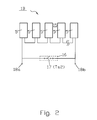
- a number of the modules 5 shown in FIG. 1 are connected in series with each other and thus combined to form a strand 15.
- the strand length may comprise six to ten modules 5.
- this strand 15 may be provided with a thermal switch 17 and bridged, which is arranged in or on a junction box 16.
- This thermal switch 17 may therefore be present in addition to the module switches 13 arranged in the individual modules 5.
- Ts2 a predetermined limit or switching temperature
- this thermal switch 17 responds. He then closes the two terminal poles 18a, 18b briefly.
- the limit or switching temperature Ts2 of this thermal switch 17 may be different than the limit or switching temperature Ts1 of the module thermal switch 13.
- the individual modules 5 can also be used in each case without the respective thermal switch 13 for cost reasons.
- a number of the strands 15 are connected in parallel to one another and electrically combined in a (only indicated) plant box 14 to form a photovoltaic system or a plant section. It is expedient to install the one or more strand thermal switch 17 in the plant box 14.
- the individual modules 5 can also be provided in each case without the respective thermal switch 13 for cost reasons.
- an inverter 19 is connected which has the two input clamps 21, 23.
- the individual strand boxes of the strands 15 are electrically connected to the terminals 21, 23.
- the AC output terminals are labeled 22, 24.
- the input terminals 21, 23 on the inverter 19 can be short-circuited by means of another thermal switch 25.
- a junction box 27 may be provided.
- the system thermal switch 25 is activated when a predefinable or permanently preset limit or switching temperature Ts3 is exceeded. When reaching this limit or switching temperature Ts3, which happens when a fire occurs, the possibly quite high output voltage applied to the terminals 21, 23, withdrawn or reduced to zero. This poses an accident risk for a person, e.g. For the purpose of extinguishing a fire, the plant approaches 1C, drastically reduced or completely avoided.
- the set or predetermined switching temperature Ts1, Ts2, Ts3 may each be in the range of 60 ° C to 100 ° C, preferably between 70 ° C and 90 ° C.
Landscapes
- Photovoltaic Devices (AREA)
Abstract
Description
- Die Erfindung bezieht sich auf einen Photovoltaikgenerator, im folgenden kurz Generator genannt. Dabei wird hier unter dem Begriff "Photovoltaikgenerator" jede Komponente, wie:
- a) das einzelne Photovoltaikmodul oder
- b) eine Zwischenanordnung, wie z.B. die Zusammenfügung mehrerer Photovoltaikmodule zu einem Photovoltaikstrang, oder
- c) ein gesamtes System als komplette Photovoltaikanlage
- Photovoltaikanlagen sind sattsam bekannt. Sie gewinnen, insbesondere in Ländern, die eine staatliche Förderung vorsehen, immer mehr an Bedeutung. Vorliegende Erfindung befasst sich weniger mit Großanlagen, die auf einem freien Feld aufgestellt werden, als vielmehr mit kleineren Anlagen im Bereich von mehreren kW elektrische Leistung, die auf Gebäudedächern montiert werden.
- Die Erfindung beruht auf der Überlegung, dass auch Wohngebäude und Wirtschaftgebäude mit Photovoltaikanlagen nicht gegen Brand gefeit sind, und dass sie bei einem Brand in einen für den Feuerwehrmann ungefährlichen Zustand überführt werden sollten.
- Photovoltaikanlagen umfassen in der Regel mehrere Photovoltaikmodule (im folgenden kurz Module genannt), die in Serie angeordnet und dabei zu einem Strang zusammengefasst sind. Mehrere dieser Stränge sind parallel zueinander angeordnet und bilden so eine Photovoltaikanlage. Zur Nutzung des gewonnenen Solarstroms ist parallel zu den Strängen ein Wechselrichter geschaltet, der den Gleichstrom in Wechselstrom umwandelt. Im Sinne obiger Definition des Begriffs "Photovoltaikgenerator" gehört der Wechselrichter nicht zum Photovoltaikgenerator selber. Ein einzelnes Photovoltaikmodul umfasst eine Vielzahl von in Serie geschalteten Photovoltaikzellen (im folgenden kurz Zellen genannt), von denen jede einzelne nach heutiger Technologie ca. 2,5 Watt liefert, d.h. die z.B. bei einer Spannung von 0,5 Volt einen Strom von 5 Ampere liefert. Beinhaltet ein Photovoltaikmodul z.B. 120 solcher Zellen, liegt an den Anschlusspolen des Moduls eine Gleich-Spannung von 60 Volt an. Sind z.B. acht dieser Module seriell zu einem Strang zusammengefasst, liegt zwischen den Enden des Strangs eine Spannung von ca. 480 Volt an.
- Im Falle einer Löschaktion der Feuerwehr unter Zuhilfenahme von Löschwasser und/oder eines Löschschaum wird die Spannung über den Wasserstrahl an den Feuerwehrmann gebracht. Steht dieser mit nassen Gummistiefeln in einer Wasserpfütze, so weist er gegenüber Masse einen relativ kleinen Übergangswiderstand auf, und er wird einen Stromschlag von ca. 500 Volt erhalten, der fatale gesundheitliche Auswirkungen haben kann.
- Die Erfindung hat es sich daher zur Aufgabe gestellt, einen Photovoltaikgenerator im Brandfall in einen für einen Löschenden, z.B. einen Feuerwehrmann, ungefährlichen Betriebszustand zu überführen.
- Diese Aufgabe wird erfindungsgemäß durch einen Thermoschalter gelöst, der beim Ansprechen eine Reduzierung der Leistung des Photovoltaikgenerators bewirkt, wobei diese Reduzierung bis auf Null heruntergehen kann.
- Eine Reduzierung der Leistung des Generators ist auf Grund des Aufbaus von Photovoltaikanlagen immer auch mit einer Reduzierung der Spannung an zumindest Teilen der Anlage verbunden. So kann der Thermoschalter am Modul selber, z.B. konstruktiv an seiner Rückseite, vorgesehen sein. Er kann aber auch einen gesamten Strang kurzschließen und damit spannungsfrei schalten, oder aber er kann die gesamte Anlage spannungsfrei schalten. Die Reduzierung der Spannung führt zu einem verringerten Gefährdungspotential.
- Eine erste vorteilhafte grundlegende Ausführungsform bezieht sich somit auf einen Photovoltaikgenerator mit einer Vielzahl von in Reihe geschalteten Photovoltaikzellen, die gemeinsam ein Photovoltaikmodul bilden, bei dem an den Enden der Reihe zwei elektrische Modul-Anschlusspole vorhanden sind, und bei dem der Thermoschalter beim Ansprechen die Modul-Anschlusspole kurzschließt und somit eine Reduzierung der Leistung des Photovoltaikgenerators bewirkt.
- Eine weitere vorteilhafte grundlegende Ausführungsform bezieht sich somit auf einen Photovoltaikgenerator mit einem Strang von elektrisch in Reihe verbundenen Photovoltaikmodulen, wobei an beiden Enden des Strangs jeweils ein elektrischer Strang-Anschlusspol vorgesehen ist, und wobei ein Thermoschalter beim Ansprechen die beiden Strang-Anschlusspole kurzschließt und somit eine Reduzierung der Leistung des Photovoltaikgenerators bewirkt.
- Und eine dritte vorteilhafte grundlegende Ausführungsform bezieht sich somit auf einen Photovoltaikgenerator mit mehreren elektrisch parallel geschalteten Strängen von in Reihe geschalteten Photovoltaikmodulen sowie mit einem zu den Strängen parallel geschalteten Wechselrichter mit zwei Gleichstrom-Eingangsklemmen, wobei ein Thermoschalter beim Ansprechen die Gleichstrompole mit einander kurzschließt und somit eine Reduzierung der Leistung des Photovoltaikgenerators bewirkt.
- Unter dem Begriff "Thermoschalter" wird hier jedes Schaltelement verstanden, welches bei Erreichen einer vorgebbaren oder vorgegebenen Temperatur oder eines anderen Feuer anzeigenden Parameters einen Schaltvorgang initiiert, der mittelbar oder unmittelbar zum Schließen oder Öffnen einer elektrischen Verbindung führt. Bei diesem Parameter kann es sich um das Auftreten von Rauch, um die Sichtbarkeit durch Luft hindurch, um die Ionisation von Luft, um den CO-Gehalt, etc. handeln. Dabei kann es sich um einen Thermoschalter mit einem mechanischen Wirkprinzip, wie z.B. um ein Bimetall-Element, handeln. Es kann sich aber auch um einen Thermoschalter mit einem elektrischen oder elektronischen Wirkprinzip, wie z.B. um einen Temperatursensor, an den eine Auswerteschaltung angeschlossen oder in diese eingebaut ist, handeln. Stattdessen kann auch ein Rauchdetektor (z.B. angeordnet auf der Rückseite des Moduls) oder ein Standard-Feuerdetektor an der Decke eines Raumes des betreffenden Gebäudes eingesetzt werden. Die Schaltoperation kann also durch ein irgendwo angeordnetes Feuer-DetektionsSystem als Sicherheitsmaßnahme ausgelöst werden.
- Eine besonders vorteilhafte Ausführungsform der Erfindung sieht vor, den dem Photovoltaikmodul zugeordneten Thermoschalter in oder an der Anschlussdose des Moduls unter- bzw. anzubringen, die in der Regel ohnehin auf der Rückseite des Moduls vorhanden ist. Außerdem ist eine Integration in den Fertigungsprozess des Moduls zweckmäßig, um die Kosten der baustellenseitigen Montage niedrig zu halten.
- Der Thermoschalter kann eine fest vorgegebene oder eine einstellbare Schalttemperatur aufweisen. Der erste Fall ist sinnvoll, wenn ein Thermoschalter direkt angeschlossen am einzelnen Modul, zur Anwendung kommt. Das Modul und seine maximale Leistung sind bekannt, woraus sich auch eine maximale Betriebstemperatur ergibt. Die Schalttemperatur wird dann geringfügig höher, z.B. in einem Bereich von 5° C bis 15° C höher, ausgelegt. Eine einstellbare Schalttemperatur ist dann in Betracht zu ziehen, wenn der Thermoschalter zwischen den Enden eines Strangs oder zwischen den Polen eines zugeordneten Wechselrichters angeordnet wird. Dann kann die dortige Temperatur bei maximaler Strang- oder Systemleistung ermittelt werden, und der Thermoschalter kann auf die für die individuelle Ausführung der Photovoltaikanlage zugeschnittene Schalttemperatur eingestellt werden. Die Schalttemperaturen liegen vorteilhafterweise in einem Bereich von 60° C bis 100° C, insbesondere zwischen 70° C und 90° C.
- Es ist selbstverständlich, dass bei einer Anlage mehrere Thermoschalter mit unterschiedlicher Zuordnung eingesetzt werden können. Das heißt, dass die Module jeweils einen eigenen Thermoschalter besitzen können, und dass zusätzlich noch weitere Thermoschalter vorhanden sein können, die beim Ansprechen eine Leistungsreduzierung eines Strangs oder der Gesamtanlage bewirken.
- Der einfachste Fall der Leistungsreduzierung ist dabei die Bildung eines Kurzschlusses zwischen den Polen der in Frage kommenden Komponenten, d.h. Modul, Strang, Gesamtanlage oder Wechselrichter.
- Ausführungsbeispiele der Erfindung werden nun anhand von 3 Figuren näher erläutert. Es zeigen:
- Fig. 1 einen Photovoltaikmodul, das mit einem Thermoschalter versehen ist,
- Fig. 2 eine Vielzahl von Photovoltaikmodulen, die zu einem Strang in Reihe geschaltet sind, wobei dem Photovoltaikstrang ein Thermoschalter zugeordnet ist, und
- Fig. 3 eine Vielzahl von Photovoltaiksträngen, die zu einer größeren Photovoltaikanlage parallel zu einander zusammengeschaltet sind, wobei der gesamten Photovoltaikanlage ein Thermoschalter zugeordnet ist.
- In Fig. 1 ist mit 1A ein besonders einfach aufgebauter Photovoltaikgenerator bezeichnet. Dieser umfasst hier eine Vielzahl von Photovoltaikzellen 3, die jeweils die kleinste Erzeugereinheit für die Umwandlung von Sonnenenergie in elektrischen Strom darstellen. Diese Vielzahl von Photovoltaikzellen 3, z.B. 120, ist miteinander in Reihe geschaltet und bildet ein Photovoltaikmodul 5. Das Modul 5 kann in einem Modulkasten 6 untergebracht sein. Die beiden Enden der Reihenschaltung sind die Anschlusspole 7, 9 des Moduls 5. Sie sind an oder in eine (gestichelt eingezeichnete) Anschlussdose 11, die sich z.B. seitwärts oder auf der Rückseite des Moduls 5 befindet, geführt. Die nach außen führenden Leitungen sind mit 7a, 9a bezeichnet. Zwischen den Anschlusspolen 7, 9 des Moduls 5 ist ein Thermoschalter 13 vorgesehen, der sich bei Überschreiten einer Grenz- oder Schalttemperatur Ts1 schließt. Abweichend von der Darstellung muss er nicht innerhalb oder an der Anschlussdose 11 angeordnet sein. Die hier gezeigte Anordnung ist jedoch besondern zweckmäßig. Der Thermoschalter 13 ruft beim Schließen einen Kurzschluss zwischen den Anschlusspolen 7, 9 hervor. Auf Grund diese Kurzschlusses bricht die Gleich-Spannung zwischen den Anschlusspolen 7 und 9 zusammen, und das Modul 5 wird im wesentlichen spannungsfrei. Im Falle eines Brandes tritt somit für eine löschende Person keine Gefahr auf.
- Anzumerken wäre auch noch, dass der Thermoschalter 13 auch außerhalb des Modulkastens 6 angeordnet sein kann. Dies kann u. U. ein besonders schnelles Ansprechen bewirken.
- Theoretisch wäre es auch denkbar, jeder Zelle 3 einen eigenen kleinen Thermoschalter 13 zuzuordnen, was denselben technisch gewünschten Effekt hätte. Dieses würde aber aus heutiger Sicht einen unwirtschaftlichen Aufwand bedeuten.
- Als Thermoschalter 13 kann ein solcher auf mechanischer oder elektronischer Basis eingesetzt werden. Es kann sich also z.B. um ein Bimetall-Element handeln. Es kann sich aber auch um einen elektronischen Temperatursensor mit Auswerteschaltung handeln. Der Thermoschalter 13 sollte bereits bei der Produktion des Moduls 5 eingebaut werden.
- Gemäß dem Photovoltaikgenerator 1 B von Fig. 2 ist eine Anzahl der in Fig. 1 dargestellten Module 5 mit einander in Reihe geschaltet und damit zu einem Strang 15 zusammengefasst. Die Stranglänge kann sechs bis zehn Module 5 umfassen.
- Zur gewünschten elektrischen Überbrückung im thermischen Gefahrenfall kann dieser Strang 15 mit einem Thermoschalter 17 versehen und überbrückt sein, der in oder an einer Anschlussdose 16 angeordnet ist. Dieser Thermoschalter 17 kann also zusätzlich zu den bei den einzelnen Modulen 5 angeordneten Modulschaltern 13 vorhanden sein. Bei Überschreiten einer vorgegebenen Grenz- oder Schalttemperatur Ts2 spricht dieser Thermoschalter 17 an. Er schließt dann die beiden Anschlusspole 18a, 18b kurz. Die Grenz- oder Schalttemperatur Ts2 dieses Thermoschalters 17 kann zu der Grenz- oder Schalttemperatur Ts1 des Modul-Thermoschalters 13 unterschiedlich sein.
- Es soll hervorgehoben werden, dass in dem Photovoltaikgenerator 1 B gemäß Fig. 2 die einzelnen Module 5 aus Kostengründen auch jeweils ohne den jeweiligen Thermoschalter 13 eingesetzt sein können.
- Bei dem Photovoltaikgenerator 1C gemäß Fig. 3 ist eine Anzahl der Stränge 15 parallel zu einander geschaltet und in einem (nur angedeuteten) Anlagenkasten 14 zu einer Photovoltaikanlage oder einem Anlagenabschnitt elektrisch zusammengefasst. Es ist zweckmäßig, den oder die einzelnen Strang-Thermoschalter 17 mit in den Anlagenkasten 14 einzubauen.
- Analog soll hier hervorgehoben werden, dass in dem Photovoltaikgenerator 1C gemäß Fig. 3 die einzelnen Module 5 aus Kostengründen auch jeweils ohne den jeweiligen Thermoschalter 13 vorgesehen sein können.
- Parallel zu den Strängen 15 ist ein Wechselrichter 19 geschaltet der die beiden Eingangsklammern 21, 23 besitzt. Mit anderen Worten: Die einzelnen Strangkästen der Stränge 15 sind elektrisch mit den Klemmen 21, 23 verbunden. Die Wechselspannungs-Ausgangsklemmen sind mit 22, 24 bezeichnet. Die Eingangsklemmen 21, 23 am Wechselrichter 19 können mittels eines weiteren Thermoschalters 25 kurzgeschlossen werden. Auch hier kann eine Anschlussdose 27 vorgesehen sein. Der Anlagen-Thermoschalter 25 wird bei Überschreiten einer vorgebbaren oder fest voreingestellten Grenz- oder Schalttemperatur Ts3 aktiviert. Beim Erreichen dieser Grenz- oder Schalttemperatur Ts3, was bei Auftreten eines Brandes geschieht, wird die unter Umständen recht hohe Ausgangsspannung, die an den Klemmen 21, 23 anliegt, zurückgenommen oder bis auf Null reduziert. Dadurch wird eine Unfallgefahr für eine Person, die z.B. zwecks Löschens eines Brandes sich der Anlage 1C nähert, drastisch reduziert oder völlig vermieden.
- Die eingestellte oder vorgegebene Schalttemperatur Ts1, Ts2, Ts3 kann jeweils im Bereich von 60° C bis 100° C, bevorzugt zwischen 70° C und 90° C, liegen. Durch diese Wahl oder Einstellung wird das Auftreten eines Brandes mit Sicherheit erfasst, so dass das Abschalten als Sicherheitsmaßnahme eingeleitet werden kann.
-
- 1A, 1B, 1C
- Photovoltaikgenerator
- 3
- Photovoltaikzelle
- 5
- Photovoltaikmodul
- 6
- Modulkasten
- 7, 9
- Anschlusspole des Moduls 5
- 7a, 9a
- Abgangsleitungen des Moduls 5
- 11
- Anschlussdose
- 13
- Thermoschalter des Moduls 5
- 14
- Anlagenkasten
- 15
- Strang
- 16
- Anschlussdose
- 17
- Thermoschalter des Strangs 15
- 18a, 18b
- Anschlusspole des Strangs 15
- 19
- Wechselrichter
- 21, 23
- Eingangsklemmen des Wechselrichters 19
- 22, 24
- Wechselspannungs-Ausgangsklemmen
- 25
- Thermoschalter am Wechselrichter 19
- 27
- Anschlussdose
- Ts1
- Grenz-, Ansprech- oder Schalttemperatur des Thermoschalters 13
- Ts2
- Grenz-, Ansprech- oder Schalttemperatur des Thermoschalters 15
- Ts3
- Grenz-, Ansprech- oder Schalttemperatur des Thermoschalters 25
Claims (10)
- Photovottaikgenerator (1A, 1 B, 1 C), gekennzeichnet durch einen Thermoschalter (13, 17, 25), der beim Ansprechen eine Reduzierung der Leistung des Photovoltaikgenerators (1A, 1 B, 1 C) bewirkt oder diese auf Null setzt.
- Photovoltaikgenerator (1 A, 1 B, 1 C) nach Anspruch 1 mit einer Vielzahl von in Reihe geschalteten Photovoltaikzellen (3), die gemeinsam ein Photovoltaikmodul (5) bilden, bei dem an den Enden der Reihe zwei elektrische Modul-Anschlusspole (7, 9) vorhanden sind, und bei dem der Thermoschalter (13) beim Ansprechen die Modul-Anschlusspole (7, 9) kurzschließt und somit eine Reduzierung der Leistung des Photovoltaikgenerators (1A, 1 B, 1 C) bewirkt.
- Photovoltaikgenerator (1A, 1 B, 1 C) nach Anspruch 1 oder 2 mit einem Strang (15) von elektrisch in Reihe verbundenen Photovoltaikmodulen (5), wobei an beiden Enden des Strangs (15) jeweils ein elektrischer Strang-Anschlusspol (18a, 18b) vorgesehen ist, und wobei ein Thermoschalter (17) beim Ansprechen die beiden Strang-Anschlusspole (18a, 18b) kurzschließt und somit eine Reduzierung der Leistung des Photovoltaikgenerators (1 B, 1 C) bewirkt.
- Photovoltaikgenerator (1 C) nach Anspruch 1, 2 oder 3 mit mehreren elektrisch parallel geschalteten Strängen (15) von in Reihe geschalteten Photovoltaikmodulen (5) sowie mit einem zu den Strängen (15) parallel geschalteten Wechselrichter (19) mit zwei Gleichstrom-Eingangsklemmen (21, 23), wobei ein Thermoschalter (25) beim Ansprechen die Gleichstrompole (21, 23) mit einander kurzschließt und somit eine Reduzierung der Leistung des Photovoltaikgenerators (1 C) bewirkt.
- Photovoltaikgenerator nach einem der Ansprüche 1 bis 4, wobei das Photovoltaikmodul (5) mit einer Anschlussdose (11) versehen ist, und wobei der dem Photovoltaikmodul (5) zugeordnete Thermoschalter (13) in oder an der Anschlussdose (11) angeordnet ist.
- Photovoltaikgenerator nach Anspruch 5, dadurch gekennzeichnet, dass der Einbau des Thermoschalters (13) fertigungsseitig bei der Produktion des Photovoltaikmoduls (5) oder der Anschlussdose (11) erfolgt ist.
- Photovoltaikgenerator nach einem der Ansprüche 3 bis 6, wobei der Strang (15) mit einem Anschlusskasten (16) versehen ist, und wobei der dem Strang (15) zugeordnete Thermoschalter (17) in oder an dem Anschlusskasten (16) angeordnet ist.
- Photovoltaikgenerator nach einem der Ansprüche 1 bis 7, dadurch gekennzeichnet, dass dem Thermoschalter (13, 17, 25) ein mechanisches Wirkprinzip zugrunde liegt, wie z.B. ein Bimetall-Element.
- Photovoltaikgenerator nach einem der Ansprüche 1 bis 7, dadurch gekennzeichnet, dass dem Thermoschalter (13, 17, 25) ein elektrisches Wirkprinzip zugrunde liegt, wie z.B. ein Temperatursensor mit Auswerteschaltung.
- Photovoltaikgenerator nach einem der Ansprüche 1 bis 9, dadurch gekennzeichnet, dass der Thermoschalter (13, 17, 25) bei einer Schalttemperatur (Ts1, Ts2, Ts3) zwischen 70° C und 90° C schaltet.
Applications Claiming Priority (1)
| Application Number | Priority Date | Filing Date | Title |
|---|---|---|---|
| DE102005017835A DE102005017835B3 (de) | 2005-04-18 | 2005-04-18 | Photovoltaikgenerator mit Thermoschalterelement |
Publications (2)
| Publication Number | Publication Date |
|---|---|
| EP1720241A2 true EP1720241A2 (de) | 2006-11-08 |
| EP1720241A3 EP1720241A3 (de) | 2011-03-23 |
Family
ID=37022997
Family Applications (1)
| Application Number | Title | Priority Date | Filing Date |
|---|---|---|---|
| EP20060006480 Withdrawn EP1720241A3 (de) | 2005-04-18 | 2006-03-29 | Photovoltaikgenerator mit Thermoschaltelement |
Country Status (3)
| Country | Link |
|---|---|
| US (1) | US20060231132A1 (de) |
| EP (1) | EP1720241A3 (de) |
| DE (1) | DE102005017835B3 (de) |
Cited By (14)
| Publication number | Priority date | Publication date | Assignee | Title |
|---|---|---|---|---|
| DE202007002077U1 (de) * | 2007-02-13 | 2008-04-03 | Dehm, Christian | Notabschaltung für Solarstromanlagen |
| FR2951872A1 (fr) * | 2009-10-28 | 2011-04-29 | Ferraz Shawmut | Installation de production de courant electrique, a partir du rayonnement solaire et procede de mise en securite d'un batiment equipe d'une telle installation |
| DE102010004395A1 (de) | 2009-09-24 | 2011-05-05 | Dehn + Söhne Gmbh + Co. Kg | Schaltungsanordnung zum Schutz von Photovoltaikmodulen |
| FR2956533A1 (fr) * | 2010-02-16 | 2011-08-19 | Cegelec Sud Est | Installation electrique comprenant des moyens generateurs de courant continu comportant au moins un module photovoltaique |
| WO2011135239A1 (fr) * | 2010-04-30 | 2011-11-03 | Augier Sa | Dispositif de sécurité pour panneaux photovoltaiques |
| DE102010047077B3 (de) * | 2010-10-01 | 2012-02-09 | Karl Swiontek | Vorrichtung zur Abschaltung eines lokalen Stromerzeugers |
| DE102010049293B3 (de) * | 2010-09-21 | 2012-02-16 | VWL Umweltcentrum für Haustechnik GmbH | Anordnung zum sicheren Außerbetriebsetzen von Photovoltaikanlagen |
| EP2439829A2 (de) | 2010-10-08 | 2012-04-11 | VWL Umweltcentrum für Haustechnik | Anordnung zum sicheren Außerbetriebsetzen von Photovoltaikanlagen |
| EP2461365A1 (de) * | 2010-12-02 | 2012-06-06 | Würth Solar GmbH & Co. KG | Photovoltaik-Modul und Kombination meherer Photovoltaik-Module |
| WO2012089947A1 (fr) | 2010-09-01 | 2012-07-05 | Mersen France Sb Sas | Court-circuiteur pour installation photovoltaïque |
| WO2012172087A1 (fr) | 2011-06-15 | 2012-12-20 | Mersen France Sb Sas | Court-circuiteur pour installation de production d'énergie électrique |
| EP2367206A3 (de) * | 2010-03-15 | 2013-01-16 | voltwerk electronics GmbH | Schutzschaltung für eine Photovoltaikanlage |
| WO2014003691A3 (en) * | 2012-06-27 | 2014-10-02 | VIPS, Jožef Korent | Process and device for safe fire extinguishing of photovoltaic power plants |
| PL441121A1 (pl) * | 2022-05-06 | 2023-11-13 | Ekovo Spółka Z Ograniczoną Odpowiedzialnością | Reduktor napięcia łańcucha fotowoltaicznego |
Families Citing this family (80)
| Publication number | Priority date | Publication date | Assignee | Title |
|---|---|---|---|---|
| GB2417551B (en) * | 2004-08-23 | 2009-06-24 | Evangelos Arkas | Solar energy trap |
| GB2420402A (en) * | 2004-11-23 | 2006-05-24 | Evangelos Arkas | Solar energy trap and turbine comprising energy absorbing chamber means |
| US10693415B2 (en) | 2007-12-05 | 2020-06-23 | Solaredge Technologies Ltd. | Testing of a photovoltaic panel |
| US11881814B2 (en) | 2005-12-05 | 2024-01-23 | Solaredge Technologies Ltd. | Testing of a photovoltaic panel |
| EP2012363A1 (de) * | 2006-04-24 | 2009-01-07 | Sharp Kabushiki Kaisha | Photovoltaisches stromerzeugungssystem und steuerverfahren für ein photovoltaisches stromerzeugungssystem |
| DE102006060815B4 (de) * | 2006-09-21 | 2013-05-29 | Solarworld Innovations Gmbh | Solarenergieerzeugungsanlage |
| US9088178B2 (en) | 2006-12-06 | 2015-07-21 | Solaredge Technologies Ltd | Distributed power harvesting systems using DC power sources |
| US8963369B2 (en) | 2007-12-04 | 2015-02-24 | Solaredge Technologies Ltd. | Distributed power harvesting systems using DC power sources |
| US8473250B2 (en) | 2006-12-06 | 2013-06-25 | Solaredge, Ltd. | Monitoring of distributed power harvesting systems using DC power sources |
| US8319471B2 (en) | 2006-12-06 | 2012-11-27 | Solaredge, Ltd. | Battery power delivery module |
| US8947194B2 (en) | 2009-05-26 | 2015-02-03 | Solaredge Technologies Ltd. | Theft detection and prevention in a power generation system |
| US8319483B2 (en) | 2007-08-06 | 2012-11-27 | Solaredge Technologies Ltd. | Digital average input current control in power converter |
| US11855231B2 (en) | 2006-12-06 | 2023-12-26 | Solaredge Technologies Ltd. | Distributed power harvesting systems using DC power sources |
| US11296650B2 (en) | 2006-12-06 | 2022-04-05 | Solaredge Technologies Ltd. | System and method for protection during inverter shutdown in distributed power installations |
| US11687112B2 (en) | 2006-12-06 | 2023-06-27 | Solaredge Technologies Ltd. | Distributed power harvesting systems using DC power sources |
| US11309832B2 (en) | 2006-12-06 | 2022-04-19 | Solaredge Technologies Ltd. | Distributed power harvesting systems using DC power sources |
| US11569659B2 (en) | 2006-12-06 | 2023-01-31 | Solaredge Technologies Ltd. | Distributed power harvesting systems using DC power sources |
| US8618692B2 (en) | 2007-12-04 | 2013-12-31 | Solaredge Technologies Ltd. | Distributed power system using direct current power sources |
| US11735910B2 (en) | 2006-12-06 | 2023-08-22 | Solaredge Technologies Ltd. | Distributed power system using direct current power sources |
| US9112379B2 (en) | 2006-12-06 | 2015-08-18 | Solaredge Technologies Ltd. | Pairing of components in a direct current distributed power generation system |
| US12316274B2 (en) | 2006-12-06 | 2025-05-27 | Solaredge Technologies Ltd. | Pairing of components in a direct current distributed power generation system |
| US8816535B2 (en) | 2007-10-10 | 2014-08-26 | Solaredge Technologies, Ltd. | System and method for protection during inverter shutdown in distributed power installations |
| US11888387B2 (en) | 2006-12-06 | 2024-01-30 | Solaredge Technologies Ltd. | Safety mechanisms, wake up and shutdown methods in distributed power installations |
| US8013472B2 (en) | 2006-12-06 | 2011-09-06 | Solaredge, Ltd. | Method for distributed power harvesting using DC power sources |
| US8384243B2 (en) | 2007-12-04 | 2013-02-26 | Solaredge Technologies Ltd. | Distributed power harvesting systems using DC power sources |
| US9130401B2 (en) | 2006-12-06 | 2015-09-08 | Solaredge Technologies Ltd. | Distributed power harvesting systems using DC power sources |
| US20090079412A1 (en) * | 2007-09-24 | 2009-03-26 | Yao Hsien Kuo | Apparatus and method for controlling the output of a photovoltaic array |
| US7884278B2 (en) * | 2007-11-02 | 2011-02-08 | Tigo Energy, Inc. | Apparatuses and methods to reduce safety risks associated with photovoltaic systems |
| US11228278B2 (en) | 2007-11-02 | 2022-01-18 | Tigo Energy, Inc. | System and method for enhanced watch dog in solar panel installations |
| US8933321B2 (en) | 2009-02-05 | 2015-01-13 | Tigo Energy, Inc. | Systems and methods for an enhanced watchdog in solar module installations |
| EP2232690B1 (de) | 2007-12-05 | 2016-08-31 | Solaredge Technologies Ltd. | Parallel geschaltete umrichter |
| US8049523B2 (en) | 2007-12-05 | 2011-11-01 | Solaredge Technologies Ltd. | Current sensing on a MOSFET |
| US11264947B2 (en) | 2007-12-05 | 2022-03-01 | Solaredge Technologies Ltd. | Testing of a photovoltaic panel |
| EP3496258B1 (de) | 2007-12-05 | 2025-02-05 | Solaredge Technologies Ltd. | Sicherheitsmechanismus in verteilten strominstallationen |
| WO2009072075A2 (en) | 2007-12-05 | 2009-06-11 | Solaredge Technologies Ltd. | Photovoltaic system power tracking method |
| EP4145691A1 (de) | 2008-03-24 | 2023-03-08 | Solaredge Technologies Ltd. | Schaltwandler mit einem hilfskommutierungsschaltkreis zur nullstromschaltung |
| EP3121922B1 (de) | 2008-05-05 | 2020-03-04 | Solaredge Technologies Ltd. | Gleichstromleistungskombinierer |
| DE102008052037B3 (de) * | 2008-10-16 | 2010-04-08 | Moeller Gmbh | Solarmodul |
| EP2200151B1 (de) * | 2008-12-19 | 2011-08-17 | ABB Research Ltd. | Photovoltaiksystem |
| EP2200152B1 (de) | 2008-12-19 | 2012-02-01 | ABB Research Ltd. | Photovoltaiksystem |
| ATE555531T1 (de) * | 2009-08-06 | 2012-05-15 | Sma Solar Technology Ag | Rückstromsensor für parallel geschaltete solarmodule |
| US10121913B2 (en) | 2009-10-19 | 2018-11-06 | Helios Focus Llc | Solar photovoltaic module safety shutdown system |
| US8859884B2 (en) * | 2009-10-19 | 2014-10-14 | Helios Focus Llc | Solar photovoltaic module safety shutdown system |
| US9941421B2 (en) | 2009-10-19 | 2018-04-10 | Helios Focus Llc | Solar photovaltaic module rapid shutdown and safety system |
| US12418177B2 (en) | 2009-10-24 | 2025-09-16 | Solaredge Technologies Ltd. | Distributed power system using direct current power sources |
| US8854193B2 (en) | 2009-12-29 | 2014-10-07 | Tigo Energy, Inc. | Systems and methods for remote or local shut-off of a photovoltaic system |
| US20110203632A1 (en) * | 2010-02-22 | 2011-08-25 | Rahul Sen | Photovoltaic devices using semiconducting nanotube layers |
| DE102010009120B4 (de) * | 2010-02-24 | 2011-09-01 | Adensis Gmbh | Photovoltaikgenerator |
| WO2011133928A2 (en) | 2010-04-22 | 2011-10-27 | Tigo Energy, Inc. | System and method for enhanced watch dog in solar panel installations |
| JP2011253767A (ja) * | 2010-06-03 | 2011-12-15 | Sony Corp | 固定台および梱包容器 |
| CN101944717B (zh) * | 2010-06-10 | 2012-11-28 | 常州天合光能有限公司 | 一种光伏发电系统 |
| DE102010036816A1 (de) | 2010-08-03 | 2012-02-09 | Newtos Ag | Verfahren und Vorrichtung zur Überwachung und Steuerung einer Photovoltaik-Anlage |
| TWI437601B (zh) * | 2010-10-08 | 2014-05-11 | Nexpower Technology Corp | 具複合金屬層保護斷路器之太陽能模組 |
| US10673222B2 (en) | 2010-11-09 | 2020-06-02 | Solaredge Technologies Ltd. | Arc detection and prevention in a power generation system |
| US10673229B2 (en) | 2010-11-09 | 2020-06-02 | Solaredge Technologies Ltd. | Arc detection and prevention in a power generation system |
| US10230310B2 (en) | 2016-04-05 | 2019-03-12 | Solaredge Technologies Ltd | Safety switch for photovoltaic systems |
| GB2485527B (en) | 2010-11-09 | 2012-12-19 | Solaredge Technologies Ltd | Arc detection and prevention in a power generation system |
| TWM410338U (en) * | 2010-11-22 | 2011-08-21 | Hon Hai Prec Ind Co Ltd | Junction box for photovoltaic power generation system |
| GB2486408A (en) | 2010-12-09 | 2012-06-20 | Solaredge Technologies Ltd | Disconnection of a string carrying direct current |
| GB2483317B (en) | 2011-01-12 | 2012-08-22 | Solaredge Technologies Ltd | Serially connected inverters |
| KR101732984B1 (ko) * | 2011-04-12 | 2017-05-08 | 엘지전자 주식회사 | 태양광 모듈 및 그 제어방법 |
| DE102011110467A1 (de) * | 2011-08-17 | 2013-02-21 | Phoenix Contact Gmbh & Co. Kg | Photovoltaikanlage, Anschlussdose und Stringanschlussdose |
| US8570005B2 (en) | 2011-09-12 | 2013-10-29 | Solaredge Technologies Ltd. | Direct current link circuit |
| DE102011121990B4 (de) * | 2011-12-22 | 2014-03-13 | Phoenix Contact Gmbh & Co. Kg | Photovoltaikanlage und Verbindungsleitung zum Anschluss eines Photvoltaikmoduls |
| GB2498365A (en) | 2012-01-11 | 2013-07-17 | Solaredge Technologies Ltd | Photovoltaic module |
| US9853565B2 (en) | 2012-01-30 | 2017-12-26 | Solaredge Technologies Ltd. | Maximized power in a photovoltaic distributed power system |
| GB2498791A (en) | 2012-01-30 | 2013-07-31 | Solaredge Technologies Ltd | Photovoltaic panel circuitry |
| GB2498790A (en) | 2012-01-30 | 2013-07-31 | Solaredge Technologies Ltd | Maximising power in a photovoltaic distributed power system |
| GB2499991A (en) | 2012-03-05 | 2013-09-11 | Solaredge Technologies Ltd | DC link circuit for photovoltaic array |
| US10115841B2 (en) | 2012-06-04 | 2018-10-30 | Solaredge Technologies Ltd. | Integrated photovoltaic panel circuitry |
| DE102012110687A1 (de) | 2012-08-27 | 2014-05-15 | Newtos Ag | Verfahren zur Lichtbogenerkennung in Photovoltaikanlagen |
| US9548619B2 (en) | 2013-03-14 | 2017-01-17 | Solaredge Technologies Ltd. | Method and apparatus for storing and depleting energy |
| US9941813B2 (en) | 2013-03-14 | 2018-04-10 | Solaredge Technologies Ltd. | High frequency multi-level inverter |
| EP2779251B1 (de) | 2013-03-15 | 2019-02-27 | Solaredge Technologies Ltd. | Umgehungsmechanismus |
| US9318974B2 (en) | 2014-03-26 | 2016-04-19 | Solaredge Technologies Ltd. | Multi-level inverter with flying capacitor topology |
| US10388802B2 (en) | 2015-07-06 | 2019-08-20 | SolarOff Systems, LLC | System and method for synchronized rapid shutdown of electrical devices |
| US12057807B2 (en) | 2016-04-05 | 2024-08-06 | Solaredge Technologies Ltd. | Chain of power devices |
| US11018623B2 (en) | 2016-04-05 | 2021-05-25 | Solaredge Technologies Ltd. | Safety switch for photovoltaic systems |
| US11177663B2 (en) | 2016-04-05 | 2021-11-16 | Solaredge Technologies Ltd. | Chain of power devices |
| JP2020120554A (ja) * | 2019-01-28 | 2020-08-06 | 東芝三菱電機産業システム株式会社 | 太陽光発電システム、太陽電池モジュールおよび太陽電池モジュール直列数調整装置 |
Citations (1)
| Publication number | Priority date | Publication date | Assignee | Title |
|---|---|---|---|---|
| DE102005018173A1 (de) * | 2005-04-19 | 2006-10-26 | Aixcon Elektrotechnik Gmbh | Verfahren zur sicheren Betriebsunterbrechung eines Photovoltaikanlage |
Family Cites Families (10)
| Publication number | Priority date | Publication date | Assignee | Title |
|---|---|---|---|---|
| GB1201537A (en) * | 1968-04-10 | 1970-08-05 | Diamond H Controls Ltd | Improvements in or relating to thermal control means |
| US4935315A (en) * | 1988-12-05 | 1990-06-19 | Hughes Aircraft Company | Cell bypass circuit |
| DE4041672A1 (de) * | 1990-12-22 | 1992-06-25 | Zsw | Ueberwachungseinrichtung fuer einen gleichstromkreis sowie damit ausgeruestete photovoltaische energiegewinnungsanalge |
| DE4204437C2 (de) * | 1992-02-14 | 2002-07-11 | Ulrich Pok | Anlage zur Wärmeenergiegewinnung mittels Photovoltaik |
| JPH1140838A (ja) * | 1997-05-20 | 1999-02-12 | Sharp Corp | 太陽電池モジュール |
| DE19746799A1 (de) * | 1997-10-23 | 1999-04-29 | Franz Hegele | Solaranlage |
| JP2000200919A (ja) * | 1998-10-30 | 2000-07-18 | Canon Inc | 太陽電池モジュ―ル及び太陽電池アレイ |
| US6593520B2 (en) * | 2000-02-29 | 2003-07-15 | Canon Kabushiki Kaisha | Solar power generation apparatus and control method therefor |
| US6653549B2 (en) * | 2000-07-10 | 2003-11-25 | Canon Kabushiki Kaisha | Photovoltaic power generation systems and methods of controlling photovoltaic power generation systems |
| JP2005175370A (ja) * | 2003-12-15 | 2005-06-30 | Oonanba Kk | 太陽電池パネル用端子ボックス |
-
2005
- 2005-04-18 DE DE102005017835A patent/DE102005017835B3/de not_active Expired - Fee Related
-
2006
- 2006-03-29 EP EP20060006480 patent/EP1720241A3/de not_active Withdrawn
- 2006-04-10 US US11/279,163 patent/US20060231132A1/en not_active Abandoned
Patent Citations (1)
| Publication number | Priority date | Publication date | Assignee | Title |
|---|---|---|---|---|
| DE102005018173A1 (de) * | 2005-04-19 | 2006-10-26 | Aixcon Elektrotechnik Gmbh | Verfahren zur sicheren Betriebsunterbrechung eines Photovoltaikanlage |
Cited By (17)
| Publication number | Priority date | Publication date | Assignee | Title |
|---|---|---|---|---|
| DE202007002077U1 (de) * | 2007-02-13 | 2008-04-03 | Dehm, Christian | Notabschaltung für Solarstromanlagen |
| DE102010004395A1 (de) | 2009-09-24 | 2011-05-05 | Dehn + Söhne Gmbh + Co. Kg | Schaltungsanordnung zum Schutz von Photovoltaikmodulen |
| WO2011051628A3 (fr) * | 2009-10-28 | 2012-03-22 | Mersen France Sb Sas | Installation de production de courant electrique, a partir du rayonnement solaire et procede de mise en securite d'un batiment equipe d'une telle installation |
| FR2951872A1 (fr) * | 2009-10-28 | 2011-04-29 | Ferraz Shawmut | Installation de production de courant electrique, a partir du rayonnement solaire et procede de mise en securite d'un batiment equipe d'une telle installation |
| FR2956533A1 (fr) * | 2010-02-16 | 2011-08-19 | Cegelec Sud Est | Installation electrique comprenant des moyens generateurs de courant continu comportant au moins un module photovoltaique |
| EP2367206A3 (de) * | 2010-03-15 | 2013-01-16 | voltwerk electronics GmbH | Schutzschaltung für eine Photovoltaikanlage |
| WO2011135239A1 (fr) * | 2010-04-30 | 2011-11-03 | Augier Sa | Dispositif de sécurité pour panneaux photovoltaiques |
| FR2959619A1 (fr) * | 2010-04-30 | 2011-11-04 | Augier Sa | Dispositif de securite pour panneaux photovoltaiques destines aux erp |
| WO2012089947A1 (fr) | 2010-09-01 | 2012-07-05 | Mersen France Sb Sas | Court-circuiteur pour installation photovoltaïque |
| CN103620715A (zh) * | 2010-09-01 | 2014-03-05 | 梅森法国Sb公司 | 用于光伏阵列的短路设备 |
| DE102010049293B3 (de) * | 2010-09-21 | 2012-02-16 | VWL Umweltcentrum für Haustechnik GmbH | Anordnung zum sicheren Außerbetriebsetzen von Photovoltaikanlagen |
| DE102010047077B3 (de) * | 2010-10-01 | 2012-02-09 | Karl Swiontek | Vorrichtung zur Abschaltung eines lokalen Stromerzeugers |
| EP2439829A2 (de) | 2010-10-08 | 2012-04-11 | VWL Umweltcentrum für Haustechnik | Anordnung zum sicheren Außerbetriebsetzen von Photovoltaikanlagen |
| EP2461365A1 (de) * | 2010-12-02 | 2012-06-06 | Würth Solar GmbH & Co. KG | Photovoltaik-Modul und Kombination meherer Photovoltaik-Module |
| WO2012172087A1 (fr) | 2011-06-15 | 2012-12-20 | Mersen France Sb Sas | Court-circuiteur pour installation de production d'énergie électrique |
| WO2014003691A3 (en) * | 2012-06-27 | 2014-10-02 | VIPS, Jožef Korent | Process and device for safe fire extinguishing of photovoltaic power plants |
| PL441121A1 (pl) * | 2022-05-06 | 2023-11-13 | Ekovo Spółka Z Ograniczoną Odpowiedzialnością | Reduktor napięcia łańcucha fotowoltaicznego |
Also Published As
| Publication number | Publication date |
|---|---|
| EP1720241A3 (de) | 2011-03-23 |
| US20060231132A1 (en) | 2006-10-19 |
| DE102005017835B3 (de) | 2006-11-23 |
Similar Documents
| Publication | Publication Date | Title |
|---|---|---|
| EP1720241A2 (de) | Photovoltaikgenerator mit Thermoschaltelement | |
| DE10107600C1 (de) | Verfahren zum Betreiben eines photovoltaischen Solarmoduls und photovoltaischer Solarmodul | |
| EP2567405B1 (de) | Verfahren zur begrenzung der generatorspannung einer photovoltaischen anlage im gefahrenfall und photovoltaische anlage | |
| DE202007002077U1 (de) | Notabschaltung für Solarstromanlagen | |
| WO2013026539A1 (de) | Anschlussdose für ein solarpanel mit einer schutzschaltung | |
| DE102011106632B4 (de) | Wechselrichter mit Überwachung des Feuchtezustandes und Betriebsverfahren | |
| WO2009006879A2 (de) | Fotovoltaikanlage | |
| EP2282388A1 (de) | Vorrichtung zur Einspeisung elektrischer Energie von einer Vielzahl von Strings von Photovoltaikmodulen in ein Stromnetz | |
| EP2101391A2 (de) | Schutzvorrichtung für Solarpanels | |
| DE102013018950A1 (de) | Generator-Anschlusskasten für erhöhte elektrische Sicherheit und reduzierte Wartungskosten bei PV-Kraftwerken | |
| DE102010049293B3 (de) | Anordnung zum sicheren Außerbetriebsetzen von Photovoltaikanlagen | |
| DE102010037760B4 (de) | Vorrichtung und Verfahren zur Spannungsfreischaltung elektrischer, in einem Gebäude oder Gebäudekomplex verlaufender Leitungen einer Photovoltaikanlage, Verwendung der Vorrichtung sowie System mit der Vorrichtung und einer Photovoltaikanlage | |
| EP2367206A2 (de) | Schutzschaltung für eine Photovoltaikanlage | |
| DE102018103740A1 (de) | Anordnung von Solarelementen und Verfahren zum Verschalten von Solarelementen | |
| DE102017107800A1 (de) | Multistrang-Photovoltaik-Anlage, Verfahren zum Betrieb einer solchen und Strangabschaltvorrichtung für eine solche | |
| DE102012009761A1 (de) | Baugruppe einer Anlage zum Erzeugen eines Gleichstroms oder eines Wechselstroms und Anlage zum Erzeugen eines Gleichstroms oder eines Wechselstroms | |
| EP2754183B1 (de) | Solarmodul, photovoltaikanlage und verfahren zum betrieb einer solchen | |
| DE202012000324U1 (de) | Anordnung zur sicheren Abschaltung der DC-Seite einer Photovoltaik-Anlage | |
| DE102010004395A1 (de) | Schaltungsanordnung zum Schutz von Photovoltaikmodulen | |
| EP2850714A2 (de) | Baugruppe einer anlage zum erzeugen eines gleichstroms oder eines wechselstroms und anlage zum erzeugen eines gleichstroms oder eines wechselstroms | |
| DE202010008494U1 (de) | Photovoltaikmodul und photovoltaische Anlage | |
| DE102023126151A1 (de) | Pv-energieerzeugungsanlage mit zentralwechselrichter | |
| BE1024328B1 (de) | Multistrang-Photovoltaik-Anlage, Verfahren zum Betrieb einer solchen und Strangabschaltvorrichtung für eine solche | |
| BE1024324B1 (de) | Photovoltaik-Anlage, Gleichstrom-Hybrid-Schalteinrichtung, Verwendung und Verfahren zum An-und Abschalten eines Photovoltaik-Strangs | |
| DE102019121882A1 (de) | Solarmodul und Verfahren zur Optimierung eines Solarmoduls |
Legal Events
| Date | Code | Title | Description |
|---|---|---|---|
| PUAI | Public reference made under article 153(3) epc to a published international application that has entered the european phase |
Free format text: ORIGINAL CODE: 0009012 |
|
| AK | Designated contracting states |
Kind code of ref document: A2 Designated state(s): AT BE BG CH CY CZ DE DK EE ES FI FR GB GR HU IE IS IT LI LT LU LV MC NL PL PT RO SE SI SK TR |
|
| AX | Request for extension of the european patent |
Extension state: AL BA HR MK YU |
|
| RAP1 | Party data changed (applicant data changed or rights of an application transferred) |
Owner name: BECK ENERGY GMBH |
|
| PUAL | Search report despatched |
Free format text: ORIGINAL CODE: 0009013 |
|
| AK | Designated contracting states |
Kind code of ref document: A3 Designated state(s): AT BE BG CH CY CZ DE DK EE ES FI FR GB GR HU IE IS IT LI LT LU LV MC NL PL PT RO SE SI SK TR |
|
| AX | Request for extension of the european patent |
Extension state: AL BA HR MK YU |
|
| RIC1 | Information provided on ipc code assigned before grant |
Ipc: H01L 31/042 20060101ALI20110216BHEP Ipc: H02H 7/18 20060101ALI20110216BHEP Ipc: H02H 5/04 20060101ALI20110216BHEP Ipc: H01L 31/02 20060101ALI20110216BHEP Ipc: H02N 6/00 20060101AFI20060929BHEP |
|
| RAP1 | Party data changed (applicant data changed or rights of an application transferred) |
Owner name: BELECTRIC SOLARKRAFTWERKE GMBH |
|
| 17P | Request for examination filed |
Effective date: 20110721 |
|
| AKX | Designation fees paid |
Designated state(s): AT BE BG CH CY CZ DE DK EE ES FI FR GB GR HU IE IS IT LI LT LU LV MC NL PL PT RO SE SI SK TR |
|
| 17Q | First examination report despatched |
Effective date: 20130419 |
|
| STAA | Information on the status of an ep patent application or granted ep patent |
Free format text: STATUS: THE APPLICATION HAS BEEN WITHDRAWN |
|
| 18W | Application withdrawn |
Effective date: 20150512 |