EP1721087B1 - Mit einer elektromagnetischen positionserfassungseinheit versehene teleskopvorrichtung - Google Patents
Mit einer elektromagnetischen positionserfassungseinheit versehene teleskopvorrichtung Download PDFInfo
- Publication number
- EP1721087B1 EP1721087B1 EP05732822A EP05732822A EP1721087B1 EP 1721087 B1 EP1721087 B1 EP 1721087B1 EP 05732822 A EP05732822 A EP 05732822A EP 05732822 A EP05732822 A EP 05732822A EP 1721087 B1 EP1721087 B1 EP 1721087B1
- Authority
- EP
- European Patent Office
- Prior art keywords
- rod
- magnetic
- telescopic device
- detectors
- cylinder
- Prior art date
- Legal status (The legal status is an assumption and is not a legal conclusion. Google has not performed a legal analysis and makes no representation as to the accuracy of the status listed.)
- Expired - Lifetime
Links
Images

Classifications
-
- F—MECHANICAL ENGINEERING; LIGHTING; HEATING; WEAPONS; BLASTING
- F15—FLUID-PRESSURE ACTUATORS; HYDRAULICS OR PNEUMATICS IN GENERAL
- F15B—SYSTEMS ACTING BY MEANS OF FLUIDS IN GENERAL; FLUID-PRESSURE ACTUATORS, e.g. SERVOMOTORS; DETAILS OF FLUID-PRESSURE SYSTEMS, NOT OTHERWISE PROVIDED FOR
- F15B15/00—Fluid-actuated devices for displacing a member from one position to another; Gearing associated therewith
- F15B15/20—Other details, e.g. assembly with regulating devices
- F15B15/28—Means for indicating the position, e.g. end of stroke
- F15B15/2815—Position sensing, i.e. means for continuous measurement of position, e.g. LVDT
- F15B15/2861—Position sensing, i.e. means for continuous measurement of position, e.g. LVDT using magnetic means
Definitions
- the present invention relates to a telescopic device such as a damper usable for example in a motor vehicle suspension.
- a damper generally comprises a cylinder slidably receiving a rod.
- a rod In some automotive applications, such as to achieve variable damping or make plate corrections, it is necessary to know the position and / or speed of the rod relative to the cylinder.
- dampers having a rod which is arranged to have a magnetic characteristic whose value varies along the rod.
- the detection device is fixed relative to the cylinder and measures the value of this characteristic. It is then possible to deduce the position of the rod from the measured value.
- Such a detection device has an intrusive character which makes the structure of the damper relatively complex.
- An object of the invention is to provide a telescopic device with position detection which is simple and reliable.
- a telescopic device comprising a cylinder slidably receiving a rod, and a device for detecting a position of the rod relative to the cylinder, the rod comprising a succession of magnetic zones and non-magnetic forming magnetic singularities arranged along the rod in patterns of which at least one has a particular configuration to form a reference pattern and the detection device is fixed relative to the cylinder and comprises a set of at least two magnetic detectors which are associated with permanent magnets and which are arranged adjacently in an axial direction of the rod so that the detector assembly has a field covering an area of the rod having an axial dimension greater than an axial dimension of the reference pattern for measuring magnetic field modulations produced by these magnets during a displacement of the rod.
- the detection of the reference pattern by the set of detectors can be immediately approximated to a position of the rod relative to the cylinder.
- the other patterns may be identical in such a way that the position is determined by counting the patterns from the reference pattern or the rod may have several reference patterns.
- the configuration of the patterns can be chosen such that the signal provided by the detectors has a smooth transition when moving from one pattern to another. This facilitates the distinction of patterns between them.
- the detection is further carried out in a simple manner.
- the invention is here described in application to a telescopic device forming a motor vehicle suspension damper.
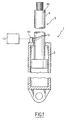
- the damper generally designated 1
- the damper comprises in known manner a cylinder 2 slidably receiving a rod 3 shown schematically.
- the rod 3 comprises magnetic zones and non-magnetic zones forming magnetic singularities arranged along the rod in patterns of which at least one has a particular configuration to constitute a reference pattern.
- the magnetic zones are non-magnetized.
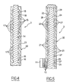
- the rod 3 thus comprises a core 4 of non-magnetic material which is externally provided with grooves 5, 6 delimiting between them flanges 7, 8.
- the grooves 5 have an identical width.
- the groove 6 has a width different from that of the grooves 5.
- the grooves 5, 6 respectively receive magnetic layers 9, 10 of corresponding width.
- the magnetic layers 9, 10 have an outer surface that is flush with the outer surface of the flanges 7, 8 such that the shaft 3 has a smooth outer surface. This makes it possible to ensure good contact of the outer surface with the unrepresented sealing elements which conventionally equip the cylinder 2.
- the collars 7 have an identical width.
- the flange 8 has a width different from that of the flanges 7.
- the magnetic layers 9, 10 and the flanges 7, 8 constitute magnetic singularities.
- the layer 10 and the flange 8 each form a single pattern, representative of a particular point on the axis of the rod 3. These patterns are referred to as reference patterns.
- the layers 9 and the flanges 7 form patterns that are described as relative because they can locate a point on the axis of the rod 3 starting from a reference pattern as will be explained later.
- the damper 1 also comprises a detection device for detecting a position of the rod 3 relative to the cylinder 2.
- the detection device comprises a bar 11 of magnetic detectors 12 adjacent.
- the detectors 12 are HALL effect detectors here and are associated with permanent magnets for detecting, in a manner known per se, a characteristic representative of a magnetic field produced by the magnets.
- the bar 11 is fixed on the cylinder 2 and extends parallel to the rod 3 facing the outer surface thereof. By this arrangement and the juxtaposition of the fields of the magnetic detectors 12 (also called field or sensitivity cones), the bar 11 has a global field covering an area of the outer surface of the rod 3 which has an axial dimension greater than an axial dimension reference motifs.
- the magnetic detectors 12 are connected to a processing unit 13 in which the positions of the reference patterns on the rod 3 are stored.
- the magnetic flux produced by the magnets will undergo a variation depending on whether they are facing a flange or a groove. This variation will be detected by the associated detectors.
- the detectors 12 opposite a flange will emit a signal representative of the presence of the flange while the detectors 12 opposite a groove will emit a signal representative of the presence of the groove.
- the flange in question is a flange 8 or the groove in question is a groove 6
- the zone of the rod 3 opposite these detectors 12 is identified so that the processing unit 13 can deduce the position of the rod 3.
- the collar in question is a flange 7 or the groove in question is a groove 5
- this information alone is not enough to identify the zone of the rod 3.
- the processing unit counts the relative patterns so that that the processing unit can at any time determine the distance separating the zone of the rod 3 opposite the magnetic detectors 12 and the identified reference pattern. From this information, the processing unit can determine the position of the rod 3 with respect to the cylinder 2.
- the displacement of the rod comprising the magnetic and non-magnetic zones in front of the fixed magnets produces a variation in the flux of these which is detected by the associated detectors.
- the use of DC-powered detectors simplifies the power supply detectors especially when the device is located on a motor vehicle where the electrical energy is supplied by a battery.
- the rod 3 comprises a core 14 of magnetic material which is provided externally with grooves 15, 16 delimiting between them flanges 17, 18.
- the grooves 15 have an identical width.
- the groove 16 has a width different from that of the grooves 15.
- the grooves 15, 16 respectively receive nonmagnetic layers 19, 20 of corresponding width.
- the nonmagnetic layers 19, 20 have an outer surface that is flush with the outer surface of the flanges 17, 18 such that the shaft 3 has a smooth outer surface.
- the core 14 is covered with a filling layer 21 which is made of non-magnetic material.
- the filling layer fills the grooves 15, 16 and covers the flanges 17, 18 with a smooth outer surface 22.
- the filling layer 21 may for example be deposited by thermal spraying or electrolysis.
- the rod 3 comprises a core 24 of magnetic material which is externally provided with grooves 25, 26 delimiting between them flanges 27, 28.
- the grooves 25, 26 and the flanges 27, 28 have as before different widths to form reference patterns and relative patterns.
- the core 24 is received in a tube 29 of non-magnetic material having a smooth outer surface.
- the tube 29 can simply provide the rod 3 a smooth outer surface simplifying sealing with the cylinder 2 or also provide a role of mechanical reinforcement.
- the detectors 12 may also be magnetoresistive detectors.
- the assembly formed by the detectors 12 has been described in the form of a bar, the detectors 12 may be independent of each other and for example simply aligned on a common direction.
- the rod 3 may also comprise alternatively a non-magnetic or magnetic core having an outer surface covered with magnetic and non-magnetic parts forming the patterns.
- the magnetic and non-magnetic portions are, for example, rings of small thickness which have different widths to form reference patterns or relative patterns.
- the core may be received in a tube which provides a protection function of the magnetic singularities and / or a function of mechanical reinforcement of the rod, or which provides a smooth external surface to the rod.
- the reference patterns can be obtained by varying the width of the grooves and / or the spacing of the grooves.
- the magnetic singularities can be achieved by combining the embodiments described.
Landscapes
- Engineering & Computer Science (AREA)
- Physics & Mathematics (AREA)
- Fluid Mechanics (AREA)
- Mechanical Engineering (AREA)
- General Engineering & Computer Science (AREA)
- Measurement Of Length, Angles, Or The Like Using Electric Or Magnetic Means (AREA)
- Vehicle Body Suspensions (AREA)
- Actuator (AREA)
- Geophysics And Detection Of Objects (AREA)
- Switches With Compound Operations (AREA)
- Switches That Are Operated By Magnetic Or Electric Fields (AREA)
Claims (7)
- Teleskopvorrichtung (1), die einen eine Stange (3) gleitend aufnehmenden Zylinder (2) und eine Vorrichtung zur Erfassung einer Stellung der Stange bezüglich des Zylinders aufweist, wobei die Stange eine Folge von magnetischen und nicht magnetischen Zonen aufweist, die magnetische Singularitäten bilden, die entlang der Stange in Mustern (5, 6, 7, 8; 15, 16, 17, 18; 25, 26, 27, 28; 51, 52; 61) angeordnet sind, wobei die Erfassungsvorrichtung bezüglich des Zylinders ortsfest ist und einen Satz (11) von mindestens zwei magnetischen Detektoren (12) aufweist, die Dauermagneten zugeordnet sind, dadurch gekennzeichnet, dass mindestens ein Muster (6, 8; 16, 18; 26, 28) eine besondere Konfiguration hat, um ein Bezugsmuster zu bilden, und dass die mindestens zwei Detektoren (12) gemäß einer axialen Richtung der Stange derart nebeneinander angeordnet sind, dass der Satz von Detektoren ein Feld hat, das eine Zone der Stange abdeckt, die eine axiale Abmessung größer als eine axiale Abmessung des Bezugsmusters hat, um Veränderungen von Magnetfeldern zu messen, die von diesen Magneten bei einer Verschiebung der Stange erzeugt werden.
- Teleskopvorrichtung (1) nach Anspruch 1, dadurch gekennzeichnet, dass die Stange (3) einen nicht magnetischen Kern (4) aufweist, der außen mit Kehlen (5, 6) versehen ist, die eine Schicht aus magnetischem Material (9, 10) aufnehmen.
- Teleskopvorrichtung (1) nach Anspruch 1, dadurch gekennzeichnet, dass die Stange (3) einen Magnetkern (14; 24) aufweist, der außen mit Kehlen (15, 16; 25, 26) versehen ist, die angeordnet sind, um die Muster zu bilden.
- Teleskopvorrichtung (1) nach Anspruch 3, dadurch gekennzeichnet, dass die Kehlen (15, 16) eine Schicht aus nicht magnetischem Material (19, 20) aufnehmen.
- Teleskopvorrichtung (1) nach Anspruch 4, dadurch gekennzeichnet, dass die Schicht aus nicht magnetischem Material (21) den Kern (24) bedeckt und eine glatte Außenfläche (22) hat.
- Teleskopvorrichtung (1) nach Anspruch 3, dadurch gekennzeichnet, dass dieser Kern (14) in einem Rohr (29) aus nicht magnetischem Material aufgenommen wird, das eine glatte Außenfläche (30) hat.
- Teleskopvorrichtung (1) nach Anspruch 1, dadurch gekennzeichnet, dass die Detektoren (12) Hall-Detektoren sind.
Priority Applications (1)
| Application Number | Priority Date | Filing Date | Title |
|---|---|---|---|
| PL05732822T PL1721087T3 (pl) | 2004-03-03 | 2005-03-03 | Urządzenie teleskopowe z elektromagnetycznym wykrywaniem położenia |
Applications Claiming Priority (2)
| Application Number | Priority Date | Filing Date | Title |
|---|---|---|---|
| FR0402175A FR2867237B1 (fr) | 2004-03-03 | 2004-03-03 | Dispositif telescopique avec detection electromagnetique de position |
| PCT/FR2005/000500 WO2005088154A1 (fr) | 2004-03-03 | 2005-03-03 | Dispositif telescopique avec detection electromagnetique de position |
Publications (2)
| Publication Number | Publication Date |
|---|---|
| EP1721087A1 EP1721087A1 (de) | 2006-11-15 |
| EP1721087B1 true EP1721087B1 (de) | 2008-01-16 |
Family
ID=34855001
Family Applications (1)
| Application Number | Title | Priority Date | Filing Date |
|---|---|---|---|
| EP05732822A Expired - Lifetime EP1721087B1 (de) | 2004-03-03 | 2005-03-03 | Mit einer elektromagnetischen positionserfassungseinheit versehene teleskopvorrichtung |
Country Status (7)
| Country | Link |
|---|---|
| EP (1) | EP1721087B1 (de) |
| AT (1) | ATE384211T1 (de) |
| DE (1) | DE602005004385T2 (de) |
| ES (1) | ES2300008T3 (de) |
| FR (1) | FR2867237B1 (de) |
| PL (1) | PL1721087T3 (de) |
| WO (1) | WO2005088154A1 (de) |
Cited By (1)
| Publication number | Priority date | Publication date | Assignee | Title |
|---|---|---|---|---|
| EP2226514A1 (de) | 2009-03-06 | 2010-09-08 | SICK STEGMANN GmbH | Vorrichtung zur Messung der axialen Position einer Kolbenstange bezüglich eines Zylindergehäuses |
Families Citing this family (4)
| Publication number | Priority date | Publication date | Assignee | Title |
|---|---|---|---|---|
| JP4713584B2 (ja) * | 2004-07-14 | 2011-06-29 | テネコ オートモティブ オペレーティング カンパニー インコーポレイテッド | 一体化された変位センサをもつショックアブソーバ |
| CN100462572C (zh) * | 2007-07-10 | 2009-02-18 | 中国航空工业第一集团公司北京航空精密机械研究所 | 智能移动作动轴 |
| GB0903961D0 (en) * | 2009-01-27 | 2009-04-22 | Renishaw Plc | Magnetic encoder scale |
| CN112594319A (zh) * | 2020-12-11 | 2021-04-02 | 中铁桥研科技有限公司 | 一种具有磁栅定位装置的粘滞阻尼器及其位移计算方法 |
Family Cites Families (5)
| Publication number | Priority date | Publication date | Assignee | Title |
|---|---|---|---|---|
| US4717874A (en) * | 1984-02-10 | 1988-01-05 | Kabushiki Kaisha Sg | Reluctance type linear position detection device |
| SE501291C2 (sv) * | 1992-09-23 | 1995-01-09 | Mecman Ab Rexroth | Anordning för positionering av kolvcylinderaggregat |
| JPH07229760A (ja) * | 1994-02-16 | 1995-08-29 | Yamaha Motor Co Ltd | エンコーダ |
| DE10010042A1 (de) * | 2000-01-13 | 2001-07-19 | Continental Teves Ag & Co Ohg | Linearer Wegsensor und dessen Verwendung als Betätigungsvorrichtung für Kraftfahrzeuge |
| JP2005531736A (ja) * | 2002-07-02 | 2005-10-20 | コンティネンタル・テーベス・アクチエンゲゼルシヤフト・ウント・コンパニー・オッフェネ・ハンデルスゲゼルシヤフト | ショックアブソーバ並びにショックアブソーバ運動を検出する装置 |
-
2004
- 2004-03-03 FR FR0402175A patent/FR2867237B1/fr not_active Expired - Fee Related
-
2005
- 2005-03-03 PL PL05732822T patent/PL1721087T3/pl unknown
- 2005-03-03 EP EP05732822A patent/EP1721087B1/de not_active Expired - Lifetime
- 2005-03-03 ES ES05732822T patent/ES2300008T3/es not_active Expired - Lifetime
- 2005-03-03 AT AT05732822T patent/ATE384211T1/de not_active IP Right Cessation
- 2005-03-03 WO PCT/FR2005/000500 patent/WO2005088154A1/fr not_active Ceased
- 2005-03-03 DE DE602005004385T patent/DE602005004385T2/de not_active Expired - Lifetime
Cited By (2)
| Publication number | Priority date | Publication date | Assignee | Title |
|---|---|---|---|---|
| EP2226514A1 (de) | 2009-03-06 | 2010-09-08 | SICK STEGMANN GmbH | Vorrichtung zur Messung der axialen Position einer Kolbenstange bezüglich eines Zylindergehäuses |
| US8151636B2 (en) | 2009-03-06 | 2012-04-10 | Sick Stegmann Gmbh | Device for measuring the axial position of a piston rod relative to a cylinder housing |
Also Published As
| Publication number | Publication date |
|---|---|
| ES2300008T3 (es) | 2008-06-01 |
| PL1721087T3 (pl) | 2008-04-30 |
| EP1721087A1 (de) | 2006-11-15 |
| WO2005088154A1 (fr) | 2005-09-22 |
| ATE384211T1 (de) | 2008-02-15 |
| DE602005004385T2 (de) | 2009-01-15 |
| FR2867237B1 (fr) | 2008-04-18 |
| DE602005004385D1 (de) | 2008-03-06 |
| FR2867237A1 (fr) | 2005-09-09 |
Similar Documents
| Publication | Publication Date | Title |
|---|---|---|
| EP0729582B1 (de) | Inkrementaler geschwindigkeits- und / oder lagegeber | |
| FR2606873A1 (fr) | Detecteur de la position du piston pour un cylindre a fluide sous pression | |
| FR3071605B1 (fr) | Module de detection d’une poignee rotative d’un vehicule motorise | |
| EP0682238B1 (de) | Magnetisches Torsionsmessgerät zur absoluten Messung von Verdrehung und Drehmoment | |
| EP1971841A2 (de) | Magnetischer kurzhubpositionssensor, im besonderen zur messung von lenksäulendrehungen | |
| EP1549910A1 (de) | Positionssensor mit variabler reluktanz | |
| EP0514530A1 (de) | Magnetischer lage- und geschwindigkeitssensor mit hallsonde. | |
| EP1781959B1 (de) | Radbremse mit einem verschleisssensor | |
| EP1721087B1 (de) | Mit einer elektromagnetischen positionserfassungseinheit versehene teleskopvorrichtung | |
| FR2757943A1 (fr) | Codeur pour capteur de position et capteur en faisant application | |
| EP1857783B1 (de) | Kodierer für Positionsmelder mit stabilisierendem Effekt auf das Gegen-Null-Gehen der magnetischen Induktion | |
| EP3244167B1 (de) | Magnetkomponente für hall-effekt-sensor, elektrische einheit und elektrischer aufladekompressor, der eine solche magnetkomponente umfasst | |
| FR2801969A1 (fr) | Capteur analogique de decalage angulaire sans contact | |
| EP0798541B1 (de) | Magnetischer Positionsgeber | |
| CH690632A5 (fr) | Moteur électromagnétique à deux rotors coaxiaux. | |
| WO2003085361A1 (fr) | Dispositif de capteur magnetique de position angulaire | |
| EP1159623B1 (de) | Vorgefertigte einheit aus dichtung mit eingebettetem geberelement und (waelz-)lager mit einer solchen einheit | |
| FR2829573A1 (fr) | Capteur magnetique de la position d'un mobile sur une trajectoire suivie par le mobile | |
| EP0593351B1 (de) | Sensor zum Messen der Winkelverschiebung eines sich bewegenden Gegenstandes | |
| FR2809487A1 (fr) | Capteur de position axiale pour une tige mobile axialement et actionneur electromagnetique de soupape qui en est equipe | |
| EP1224110B1 (de) | Elektronisches lenksäulenmodul | |
| FR2716713A1 (fr) | Installation pour mesurer une course ou un angle. | |
| EP0658772A1 (de) | Magnetischer Fühler mit magnetoresistivem Effekt | |
| FR2767584A1 (fr) | Indicateur de vitesse de rotation fonctionnant par induction pour relever la vitesse de rotation d'une roue de vehicule automobile | |
| FR2829574A1 (fr) | Capteur de la position d'un objet mobile, sur une trajectoire rectiligne |
Legal Events
| Date | Code | Title | Description |
|---|---|---|---|
| PUAI | Public reference made under article 153(3) epc to a published international application that has entered the european phase |
Free format text: ORIGINAL CODE: 0009012 |
|
| 17P | Request for examination filed |
Effective date: 20060904 |
|
| AK | Designated contracting states |
Kind code of ref document: A1 Designated state(s): AT BE BG CH CY CZ DE DK EE ES FI FR GB GR HU IE IS IT LI LT LU MC NL PL PT RO SE SI SK TR |
|
| RIN1 | Information on inventor provided before grant (corrected) |
Inventor name: QUEDEVILLE, NICOLAS Inventor name: RAMPILLON, FLORENT Inventor name: MAERKY, CHRISTOPHE |
|
| DAX | Request for extension of the european patent (deleted) | ||
| GRAP | Despatch of communication of intention to grant a patent |
Free format text: ORIGINAL CODE: EPIDOSNIGR1 |
|
| GRAS | Grant fee paid |
Free format text: ORIGINAL CODE: EPIDOSNIGR3 |
|
| GRAA | (expected) grant |
Free format text: ORIGINAL CODE: 0009210 |
|
| AK | Designated contracting states |
Kind code of ref document: B1 Designated state(s): AT BE BG CH CY CZ DE DK EE ES FI FR GB GR HU IE IS IT LI LT LU MC NL PL PT RO SE SI SK TR |
|
| REG | Reference to a national code |
Ref country code: GB Ref legal event code: FG4D Free format text: NOT ENGLISH |
|
| REG | Reference to a national code |
Ref country code: CH Ref legal event code: EP |
|
| REG | Reference to a national code |
Ref country code: IE Ref legal event code: FG4D Free format text: LANGUAGE OF EP DOCUMENT: FRENCH |
|
| GBT | Gb: translation of ep patent filed (gb section 77(6)(a)/1977) |
Effective date: 20080213 |
|
| REF | Corresponds to: |
Ref document number: 602005004385 Country of ref document: DE Date of ref document: 20080306 Kind code of ref document: P |
|
| REG | Reference to a national code |
Ref country code: SE Ref legal event code: TRGR |
|
| REG | Reference to a national code |
Ref country code: PL Ref legal event code: T3 |
|
| PG25 | Lapsed in a contracting state [announced via postgrant information from national office to epo] |
Ref country code: NL Free format text: LAPSE BECAUSE OF FAILURE TO SUBMIT A TRANSLATION OF THE DESCRIPTION OR TO PAY THE FEE WITHIN THE PRESCRIBED TIME-LIMIT Effective date: 20080116 |
|
| REG | Reference to a national code |
Ref country code: ES Ref legal event code: FG2A Ref document number: 2300008 Country of ref document: ES Kind code of ref document: T3 |
|
| NLV1 | Nl: lapsed or annulled due to failure to fulfill the requirements of art. 29p and 29m of the patents act | ||
| PG25 | Lapsed in a contracting state [announced via postgrant information from national office to epo] |
Ref country code: LT Free format text: LAPSE BECAUSE OF FAILURE TO SUBMIT A TRANSLATION OF THE DESCRIPTION OR TO PAY THE FEE WITHIN THE PRESCRIBED TIME-LIMIT Effective date: 20080116 Ref country code: FI Free format text: LAPSE BECAUSE OF FAILURE TO SUBMIT A TRANSLATION OF THE DESCRIPTION OR TO PAY THE FEE WITHIN THE PRESCRIBED TIME-LIMIT Effective date: 20080116 Ref country code: IS Free format text: LAPSE BECAUSE OF FAILURE TO SUBMIT A TRANSLATION OF THE DESCRIPTION OR TO PAY THE FEE WITHIN THE PRESCRIBED TIME-LIMIT Effective date: 20080516 |
|
| PG25 | Lapsed in a contracting state [announced via postgrant information from national office to epo] |
Ref country code: AT Free format text: LAPSE BECAUSE OF FAILURE TO SUBMIT A TRANSLATION OF THE DESCRIPTION OR TO PAY THE FEE WITHIN THE PRESCRIBED TIME-LIMIT Effective date: 20080116 Ref country code: BG Free format text: LAPSE BECAUSE OF FAILURE TO SUBMIT A TRANSLATION OF THE DESCRIPTION OR TO PAY THE FEE WITHIN THE PRESCRIBED TIME-LIMIT Effective date: 20080416 |
|
| PG25 | Lapsed in a contracting state [announced via postgrant information from national office to epo] |
Ref country code: SI Free format text: LAPSE BECAUSE OF FAILURE TO SUBMIT A TRANSLATION OF THE DESCRIPTION OR TO PAY THE FEE WITHIN THE PRESCRIBED TIME-LIMIT Effective date: 20080116 Ref country code: PT Free format text: LAPSE BECAUSE OF FAILURE TO SUBMIT A TRANSLATION OF THE DESCRIPTION OR TO PAY THE FEE WITHIN THE PRESCRIBED TIME-LIMIT Effective date: 20080616 |
|
| REG | Reference to a national code |
Ref country code: IE Ref legal event code: FD4D |
|
| PG25 | Lapsed in a contracting state [announced via postgrant information from national office to epo] |
Ref country code: SK Free format text: LAPSE BECAUSE OF FAILURE TO SUBMIT A TRANSLATION OF THE DESCRIPTION OR TO PAY THE FEE WITHIN THE PRESCRIBED TIME-LIMIT Effective date: 20080116 Ref country code: MC Free format text: LAPSE BECAUSE OF NON-PAYMENT OF DUE FEES Effective date: 20080331 Ref country code: IE Free format text: LAPSE BECAUSE OF FAILURE TO SUBMIT A TRANSLATION OF THE DESCRIPTION OR TO PAY THE FEE WITHIN THE PRESCRIBED TIME-LIMIT Effective date: 20080116 Ref country code: DK Free format text: LAPSE BECAUSE OF FAILURE TO SUBMIT A TRANSLATION OF THE DESCRIPTION OR TO PAY THE FEE WITHIN THE PRESCRIBED TIME-LIMIT Effective date: 20080116 |
|
| PLBE | No opposition filed within time limit |
Free format text: ORIGINAL CODE: 0009261 |
|
| STAA | Information on the status of an ep patent application or granted ep patent |
Free format text: STATUS: NO OPPOSITION FILED WITHIN TIME LIMIT |
|
| PG25 | Lapsed in a contracting state [announced via postgrant information from national office to epo] |
Ref country code: RO Free format text: LAPSE BECAUSE OF FAILURE TO SUBMIT A TRANSLATION OF THE DESCRIPTION OR TO PAY THE FEE WITHIN THE PRESCRIBED TIME-LIMIT Effective date: 20080116 |
|
| 26N | No opposition filed |
Effective date: 20081017 |
|
| PG25 | Lapsed in a contracting state [announced via postgrant information from national office to epo] |
Ref country code: EE Free format text: LAPSE BECAUSE OF FAILURE TO SUBMIT A TRANSLATION OF THE DESCRIPTION OR TO PAY THE FEE WITHIN THE PRESCRIBED TIME-LIMIT Effective date: 20080116 |
|
| PG25 | Lapsed in a contracting state [announced via postgrant information from national office to epo] |
Ref country code: CY Free format text: LAPSE BECAUSE OF FAILURE TO SUBMIT A TRANSLATION OF THE DESCRIPTION OR TO PAY THE FEE WITHIN THE PRESCRIBED TIME-LIMIT Effective date: 20080116 |
|
| REG | Reference to a national code |
Ref country code: CH Ref legal event code: PL |
|
| PG25 | Lapsed in a contracting state [announced via postgrant information from national office to epo] |
Ref country code: CH Free format text: LAPSE BECAUSE OF NON-PAYMENT OF DUE FEES Effective date: 20090331 Ref country code: LI Free format text: LAPSE BECAUSE OF NON-PAYMENT OF DUE FEES Effective date: 20090331 |
|
| PG25 | Lapsed in a contracting state [announced via postgrant information from national office to epo] |
Ref country code: HU Free format text: LAPSE BECAUSE OF FAILURE TO SUBMIT A TRANSLATION OF THE DESCRIPTION OR TO PAY THE FEE WITHIN THE PRESCRIBED TIME-LIMIT Effective date: 20080717 Ref country code: LU Free format text: LAPSE BECAUSE OF NON-PAYMENT OF DUE FEES Effective date: 20080303 |
|
| PG25 | Lapsed in a contracting state [announced via postgrant information from national office to epo] |
Ref country code: TR Free format text: LAPSE BECAUSE OF FAILURE TO SUBMIT A TRANSLATION OF THE DESCRIPTION OR TO PAY THE FEE WITHIN THE PRESCRIBED TIME-LIMIT Effective date: 20080116 |
|
| PG25 | Lapsed in a contracting state [announced via postgrant information from national office to epo] |
Ref country code: GR Free format text: LAPSE BECAUSE OF FAILURE TO SUBMIT A TRANSLATION OF THE DESCRIPTION OR TO PAY THE FEE WITHIN THE PRESCRIBED TIME-LIMIT Effective date: 20080417 |
|
| REG | Reference to a national code |
Ref country code: FR Ref legal event code: PLFP Year of fee payment: 12 |
|
| PGFP | Annual fee paid to national office [announced via postgrant information from national office to epo] |
Ref country code: ES Payment date: 20160329 Year of fee payment: 12 Ref country code: DE Payment date: 20160316 Year of fee payment: 12 Ref country code: CZ Payment date: 20160224 Year of fee payment: 12 |
|
| PGFP | Annual fee paid to national office [announced via postgrant information from national office to epo] |
Ref country code: SE Payment date: 20160318 Year of fee payment: 12 Ref country code: GB Payment date: 20160318 Year of fee payment: 12 Ref country code: PL Payment date: 20160218 Year of fee payment: 12 |
|
| PGFP | Annual fee paid to national office [announced via postgrant information from national office to epo] |
Ref country code: BE Payment date: 20160330 Year of fee payment: 12 Ref country code: IT Payment date: 20160317 Year of fee payment: 12 Ref country code: FR Payment date: 20160331 Year of fee payment: 12 |
|
| REG | Reference to a national code |
Ref country code: DE Ref legal event code: R119 Ref document number: 602005004385 Country of ref document: DE |
|
| PG25 | Lapsed in a contracting state [announced via postgrant information from national office to epo] |
Ref country code: CZ Free format text: LAPSE BECAUSE OF NON-PAYMENT OF DUE FEES Effective date: 20170303 |
|
| REG | Reference to a national code |
Ref country code: SE Ref legal event code: EUG |
|
| GBPC | Gb: european patent ceased through non-payment of renewal fee |
Effective date: 20170303 |
|
| PG25 | Lapsed in a contracting state [announced via postgrant information from national office to epo] |
Ref country code: SE Free format text: LAPSE BECAUSE OF NON-PAYMENT OF DUE FEES Effective date: 20170304 |
|
| REG | Reference to a national code |
Ref country code: FR Ref legal event code: ST Effective date: 20171130 |
|
| PG25 | Lapsed in a contracting state [announced via postgrant information from national office to epo] |
Ref country code: DE Free format text: LAPSE BECAUSE OF NON-PAYMENT OF DUE FEES Effective date: 20171003 Ref country code: FR Free format text: LAPSE BECAUSE OF NON-PAYMENT OF DUE FEES Effective date: 20170331 |
|
| PG25 | Lapsed in a contracting state [announced via postgrant information from national office to epo] |
Ref country code: GB Free format text: LAPSE BECAUSE OF NON-PAYMENT OF DUE FEES Effective date: 20170303 Ref country code: IT Free format text: LAPSE BECAUSE OF NON-PAYMENT OF DUE FEES Effective date: 20170303 |
|
| REG | Reference to a national code |
Ref country code: BE Ref legal event code: MM Effective date: 20170331 |
|
| PG25 | Lapsed in a contracting state [announced via postgrant information from national office to epo] |
Ref country code: BE Free format text: LAPSE BECAUSE OF NON-PAYMENT OF DUE FEES Effective date: 20170331 |
|
| REG | Reference to a national code |
Ref country code: ES Ref legal event code: FD2A Effective date: 20180629 |
|
| PG25 | Lapsed in a contracting state [announced via postgrant information from national office to epo] |
Ref country code: ES Free format text: LAPSE BECAUSE OF NON-PAYMENT OF DUE FEES Effective date: 20170304 |
|
| PG25 | Lapsed in a contracting state [announced via postgrant information from national office to epo] |
Ref country code: PL Free format text: LAPSE BECAUSE OF NON-PAYMENT OF DUE FEES Effective date: 20170303 |