EP1721375B1 - Dispositif de protection destine a un branchement de recepteur - Google Patents
Dispositif de protection destine a un branchement de recepteur Download PDFInfo
- Publication number
- EP1721375B1 EP1721375B1 EP04717017A EP04717017A EP1721375B1 EP 1721375 B1 EP1721375 B1 EP 1721375B1 EP 04717017 A EP04717017 A EP 04717017A EP 04717017 A EP04717017 A EP 04717017A EP 1721375 B1 EP1721375 B1 EP 1721375B1
- Authority
- EP
- European Patent Office
- Prior art keywords
- protective
- protection
- protective device
- switching device
- fuse
- Prior art date
- Legal status (The legal status is an assumption and is not a legal conclusion. Google has not performed a legal analysis and makes no representation as to the accuracy of the status listed.)
- Expired - Lifetime
Links
- 230000001681 protective effect Effects 0.000 title claims abstract description 47
- 239000004065 semiconductor Substances 0.000 claims description 14
- 238000012423 maintenance Methods 0.000 claims description 8
- 238000009434 installation Methods 0.000 claims 1
- 230000011664 signaling Effects 0.000 claims 1
- 230000006870 function Effects 0.000 description 4
- 230000009993 protective function Effects 0.000 description 4
- 239000004020 conductor Substances 0.000 description 2
- 238000002955 isolation Methods 0.000 description 2
- 230000006978 adaptation Effects 0.000 description 1
- 230000006378 damage Effects 0.000 description 1
- 230000001419 dependent effect Effects 0.000 description 1
- 238000013021 overheating Methods 0.000 description 1
- 238000004088 simulation Methods 0.000 description 1
Images
Classifications
-
- H—ELECTRICITY
- H02—GENERATION; CONVERSION OR DISTRIBUTION OF ELECTRIC POWER
- H02H—EMERGENCY PROTECTIVE CIRCUIT ARRANGEMENTS
- H02H7/00—Emergency protective circuit arrangements specially adapted for specific types of electric machines or apparatus or for sectionalised protection of cable or line systems, and effecting automatic switching in the event of an undesired change from normal working conditions
- H02H7/08—Emergency protective circuit arrangements specially adapted for specific types of electric machines or apparatus or for sectionalised protection of cable or line systems, and effecting automatic switching in the event of an undesired change from normal working conditions for dynamo-electric motors
- H02H7/0833—Emergency protective circuit arrangements specially adapted for specific types of electric machines or apparatus or for sectionalised protection of cable or line systems, and effecting automatic switching in the event of an undesired change from normal working conditions for dynamo-electric motors for electric motors with control arrangements
-
- H—ELECTRICITY
- H02—GENERATION; CONVERSION OR DISTRIBUTION OF ELECTRIC POWER
- H02H—EMERGENCY PROTECTIVE CIRCUIT ARRANGEMENTS
- H02H7/00—Emergency protective circuit arrangements specially adapted for specific types of electric machines or apparatus or for sectionalised protection of cable or line systems, and effecting automatic switching in the event of an undesired change from normal working conditions
- H02H7/08—Emergency protective circuit arrangements specially adapted for specific types of electric machines or apparatus or for sectionalised protection of cable or line systems, and effecting automatic switching in the event of an undesired change from normal working conditions for dynamo-electric motors
- H02H7/0822—Integrated protection, motor control centres
Definitions
- the invention relates to a protective device for a load feeder.
- Load feeders today are either built without fuses (eg with circuit breaker) or with a fuse. In both types, it is possible to protect a provided with mechanical switching devices load feeder so that the switching devices are still functional after a short circuit. This is referred to in the relevant product standard IEC 947 as "assignment type 2". In a fuseless load feeder with an electronic switching device this is destroyed in the event of a short circuit without significant oversizing of the power semiconductor in the rule. Therefore, when using electronic switchgear usually fuses are used. In such a fused load feeder with an electronic switching device, however, the "type 2 assignment" can only be achieved by additional components, such as special semiconductor fuses or expensive full-range fuses. Such a switching device is off EP 0583 762 known.
- the object of the present invention is to find a structurally simple solution with which comprehensive protection of a consumer feeder can be achieved.
- a protective device according to claim 1 or by an arrangement according to claim 7. Thereafter, a protective device with a first protective element for providing a motor and line protection and with a fuse having, integrated second protective element for providing a short-circuit protection is provided.
- the second protective element in such a way that at the same time there is a semiconductor protection for an electronic switching device provided in the load feeder.
- the second protection element allows not only a short-circuit protection for the entire load feeder at the same time also a semiconductor protection for electronic switching devices in the load feeder.
- This is achieved, in particular, by the choice of a suitable fuse having, for example, a suitable motor start-up overload capability and low current-carrying values for semiconductor protection.
- the "assignment type 2" can be achieved in conjunction with an electronic switching device. Additional components are no longer required.
- a basic idea of the invention is to combine several protective functions in a single protective device.
- the protective device according to the invention provides motor and line protection (overload protection), short-circuit protection for the entire load feeder, and a protective function for the semiconductor switches.
- Such a combination makes it possible to reduce the space required. Since no additional fuse holders are required, the required cabinet space is reduced. Expensive additional protection components and complex wiring are no longer required.
- the fuse can be transferred from its operating position to a maintenance position.
- a simple electrical isolation for maintenance or repair work is achieved.
- a manually operable or equipped with a motor drive unit for swiveling out or pulling out of the fuse is provided.
- a lock to secure the maintenance position for example in the form of a lock
- the protective device is secured in a further embodiment of the invention against accidental reclosing.
- an auxiliary switch is provided for reporting the securing condition.
- the auxiliary switch is preferably designed such that it, for example, in conjunction with a reporting element, indicating a triggering of the fuse.
- the first protective element comprises an overload relay.
- the motor and line protection is ensured in a simple yet reliable manner. If the tripping characteristic of the motor protection is adapted to the overload capacity of the electronic switching device, the use of a mechanical switching device provided in addition to the electronic switching device for switching off in the event of an overload is no longer necessary. In addition, by dimensioning the overload tripping behavior, the dimensioning of the power semiconductors in the downstream electronic switching device can be designed significantly more cost-effectively.
- the overload relay can be designed as a mechanical bimetallic release or as an electronically realized variant with a simulation of a thermal tripping characteristic. It does not matter if the overload relay is external or self-powered.
- an overload variant has been found that allows a wide range setting of the rated current. This makes it possible to cover a wide range of rated motor currents with a comparatively small number of different protective devices. It is advantageous in this context if the first protective element and / or the setting element for the rated current is modularly exchangeable. Thus, a use of a single basic device for a variety of applications is possible.
- a thermistor can also be provided to provide the motor protection function.
- both protective elements are used side by side. This is particularly useful if you also want to respond to such overheating situations that does not cover the overload relay.
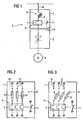
- FIG. 1 an arrangement with a protective device 1 according to the invention and an electronic switching device 2 is shown.
- the load feeder 3 comprises, in addition to this arrangement according to the invention, a consumer in the form of a motor 4.
- protection device 1 and switching device 2 are coordinated. In particular, the widths 5 of protection device 1 and switching device 2 are the same. The total required for the protection functions achieved control cabinet surface is reduced compared to known solutions.
- the protection device 1 consists essentially of a first protection element 6 with an overload relay 7 for providing a motor and line protection and an integrated second protection element 8 with fuses 9 to provide a short-circuit protection.
- First protective element 6 and second protective element 8, and thus all the protective functions that can be realized with the protective device 1, are matched to one another in such a way that a user receives a ready-to-use device without any configuration effort.
- the selection of the protective device 1 can be made on the basis of the rated data of the motor 4.
- An application of the protective device 1 according to the invention can also be carried out in an arrangement with mechanical switching devices (contactors) (not shown).
- the "assignment type 2" can be achieved, in which this was not the case before.
- FIG. 2 shows a protection device 1 according to the invention in the operating position in a greatly simplified representation, wherein a fuse three current conductors 10 takes place.
- the first protective element 6 comprises a three-pole electrothermal overload relay 7. This is used in conjunction with a switch 11 to turn off the downstream in the load feeder 3 electronic switching device 2 in the event of overloading and thus to protect the switching device 2 from destruction. As a result, on the one hand, the motor protection and due to the overload protection function for the motor 4, the line protection is provided simultaneously.
- the tripping characteristic of the overload relay 7 is matched to the overload capacity of the electronic switching device 2. Oversizing the power semiconductors in the switching device 2 is no longer necessary due to the adaptation of the overload tripping behavior of the overload relay 7 to the switching device 2.
- the second protective element 8 comprises for all current conductors 10 fuses 9, which are designed such that they cause at the same time not only a short-circuit protection for the entire load feeder 3 but also a semiconductor protection for the electronic switching device 2.
- partial area fuses of type aM are used in the present example. These have both a suitable overload capacity for the motor startup and low current shutdown values for the protection of the semiconductors in the switching device 2.
- the fuses 9 can be manually transferred from their operating position to a maintenance position, so that a simple electrical isolation is possible. Due to the small size of the fuses used 9 of 10 x 38 mm, a width of 45 mm is possible for the three-phase protection device 1.
- FIG. 3 represents a protection device according to the invention 1 in its maintenance position. In this case, the fuses 9 are pivoted out of the operating position.
Landscapes
- Emergency Protection Circuit Devices (AREA)
- Protection Of Generators And Motors (AREA)
- Vending Machines For Individual Products (AREA)
- Slot Machines And Peripheral Devices (AREA)
Claims (8)
- Appareil ( 1 ) de protection pour la protection d'un branchement ( 3 ) d'utilisateur, comprenant un premier élément ( 6 ) de protection pour disposer d'une protection de moteur et vis-à-vis d'une surcharge, et un deuxième élément ( 8 ) de protection comportant un fusible ( 9 ) pour disposer d'une protection vis-à-vis d'un court-circuit, caractérisé en ce que le fusible ( 9 ) est tel qu'il a, à la fois, une capacité de surcharge appropriée pour le démarrage du moteur et une valeur basse d'interruption du courant pour la protection des semiconducteurs d'un appareil ( 2 ) de commutation à semiconducteurs, monté en série et disposé entre l'appareil ( 1 ) de protection et le moteur ( 4 ).
- Appareil ( 1 ) de protection suivant la revendication 1, caractérisé en ce que le fusible ( 9 ) peut passer de sa position de fonctionnement à une position d'entretien.
- Appareil ( 1 ) de protection suivant la revendication 2, caractérisé par un verrouillage pour assurer la position d'entretien.
- Appareil ( 1 ) de protection suivant l'une des revendications 1 à 3, caractérisé par un commutateur auxiliaire pour indiquer l'état du fusible ( 9 ).
- Appareil ( 1 ) de protection suivant l'une des revendications 1 à 4, caractérisé en ce que le premier élément ( 6 ) de protection comporte un relais ( 7 ) de surcharge.
- Appareil ( 1 ) de protection suivant l'une des revendications 1 à 5, caractérisé en ce que le comportement de déclenchement du premier élément ( 6 ) de protection est adapté au dimensionnement d'un appareil ( 2 ) de commutation.
- Branchement ( 3 ) d'utilisateur comprenant un appareil ( 1 ) de protection suivant l'une des revendications 1 à 6, et un appareil ( 2 ) de commutation à semiconducteurs monté en série.
- Branchement ( 3 ) d'utilisateur suivant la revendication 7, caractérisé en ce que l'appareil ( 1 ) de protection et l'appareil ( 2 ) de commutation à semiconducteurs ont des dimensions de montage unitaires.
Applications Claiming Priority (1)
| Application Number | Priority Date | Filing Date | Title |
|---|---|---|---|
| PCT/DE2004/000422 WO2005086311A1 (fr) | 2004-03-04 | 2004-03-04 | Dispositif de protection destine a un branchement de recepteur |
Publications (2)
| Publication Number | Publication Date |
|---|---|
| EP1721375A1 EP1721375A1 (fr) | 2006-11-15 |
| EP1721375B1 true EP1721375B1 (fr) | 2011-06-22 |
Family
ID=34917113
Family Applications (1)
| Application Number | Title | Priority Date | Filing Date |
|---|---|---|---|
| EP04717017A Expired - Lifetime EP1721375B1 (fr) | 2004-03-04 | 2004-03-04 | Dispositif de protection destine a un branchement de recepteur |
Country Status (6)
| Country | Link |
|---|---|
| US (1) | US20070183102A1 (fr) |
| EP (1) | EP1721375B1 (fr) |
| CN (1) | CN1926741A (fr) |
| AT (1) | ATE514218T1 (fr) |
| DE (1) | DE112004002846A5 (fr) |
| WO (1) | WO2005086311A1 (fr) |
Cited By (1)
| Publication number | Priority date | Publication date | Assignee | Title |
|---|---|---|---|---|
| DE102017011373A1 (de) | 2017-12-11 | 2019-06-13 | Fachhochschule Südwestfalen | Mess- und Steuerelektronik für Niederspannungsschaltanlagen |
Families Citing this family (2)
| Publication number | Priority date | Publication date | Assignee | Title |
|---|---|---|---|---|
| DE102008018256B4 (de) | 2008-03-31 | 2023-04-27 | Siemens Aktiengesellschaft | Steuermodul mit Anschlusseinrichtungen zum Anschluss an Anschlussklemmen eines Verbraucherabzweiges sowie Verbraucherabzweig |
| AU2013401941B2 (en) | 2013-09-30 | 2019-03-28 | Schneider Electric USA, Inc. | Distributed arc fault protection between outlet and circuit breaker |
Family Cites Families (15)
| Publication number | Priority date | Publication date | Assignee | Title |
|---|---|---|---|---|
| US2342852A (en) * | 1942-11-19 | 1944-02-29 | Bulldog Electric Prod Co | Switch |
| US3638157A (en) * | 1969-05-28 | 1972-01-25 | Westinghouse Electric Corp | Combination motor starter |
| US4054818A (en) * | 1975-10-20 | 1977-10-18 | Risberg Robert L | Solid state current source polyphase inverter induction motor drive |
| US4309735A (en) * | 1979-10-30 | 1982-01-05 | Harnischfeger Corporation | Protective circuits for converter-supplied D.C. motor |
| FR2561816B1 (fr) * | 1984-03-20 | 1988-06-10 | Telemecanique Electrique | Combine pour la coupure en charge et le sectionnement visible d'un circuit electrique |
| US4691197A (en) * | 1985-06-24 | 1987-09-01 | Eaton Corporation | Blown fuse indicator |
| US5127085A (en) * | 1991-04-01 | 1992-06-30 | General Motors Corporation | Ride-through protection circuit for a voltage source inverter traction motor drive |
| US5223681A (en) * | 1991-10-18 | 1993-06-29 | Square D Company | Current limiting circuit breaker with over-molded magnet and metal plates |
| DE9211138U1 (de) * | 1992-08-20 | 1993-02-04 | Klöckner-Moeller GmbH, 5300 Bonn | Schaltvorrichtung |
| AT401440B (de) * | 1993-08-25 | 1996-09-25 | Harbauer Heinrich | Überwachungseinrichtung für zwei oder mehrere leitungen, insbesondere für drei leitungen, die phasenverschobenen wechselstrom führen |
| DE19635055A1 (de) * | 1996-08-30 | 1998-03-05 | Abb Patent Gmbh | Elektrisches Niederspannungsschaltgerät |
| US5896021A (en) * | 1997-02-06 | 1999-04-20 | General Electric Company | Removal of moisture from induction motors |
| US5822164A (en) * | 1997-05-19 | 1998-10-13 | Eaton Corporation | Pre-engineered combination starter for multiple motor sizes |
| US6315617B1 (en) * | 1998-03-27 | 2001-11-13 | Sabah Naser Al-Sabah | Apparatus and method for distributing power from a power supply |
| US6853289B2 (en) * | 2000-10-24 | 2005-02-08 | Cooper Technologies Company | Fuse handle for fused disconnect switch |
-
2004
- 2004-03-04 DE DE112004002846T patent/DE112004002846A5/de not_active Withdrawn
- 2004-03-04 AT AT04717017T patent/ATE514218T1/de active
- 2004-03-04 US US10/591,448 patent/US20070183102A1/en not_active Abandoned
- 2004-03-04 WO PCT/DE2004/000422 patent/WO2005086311A1/fr not_active Ceased
- 2004-03-04 EP EP04717017A patent/EP1721375B1/fr not_active Expired - Lifetime
- 2004-03-04 CN CNA2004800422864A patent/CN1926741A/zh active Pending
Cited By (1)
| Publication number | Priority date | Publication date | Assignee | Title |
|---|---|---|---|---|
| DE102017011373A1 (de) | 2017-12-11 | 2019-06-13 | Fachhochschule Südwestfalen | Mess- und Steuerelektronik für Niederspannungsschaltanlagen |
Also Published As
| Publication number | Publication date |
|---|---|
| CN1926741A (zh) | 2007-03-07 |
| EP1721375A1 (fr) | 2006-11-15 |
| DE112004002846A5 (de) | 2007-05-24 |
| US20070183102A1 (en) | 2007-08-09 |
| WO2005086311A1 (fr) | 2005-09-15 |
| ATE514218T1 (de) | 2011-07-15 |
Similar Documents
| Publication | Publication Date | Title |
|---|---|---|
| DE602005000540T2 (de) | Überspannungs-Schutzeinrichtung | |
| EP1380042B1 (fr) | Unite de distribution, notamment demarreur de moteur, pour un consommateur | |
| DE19739780B4 (de) | Drehstrommotor | |
| EP1685578A1 (fr) | Appareil de protection de commutation securise | |
| DE102010021068B4 (de) | Leitungsschutzschalter mit Lichtbogenerfassungseinheit | |
| EP0261606A2 (fr) | Circuit de protection | |
| DE19956698C1 (de) | Anordnung mit zwei Schützen in Reihenschaltung | |
| EP1721375A1 (fr) | Dispositif de protection destine a un branchement de recepteur | |
| DE102023202388A1 (de) | Geräte-Modul, Reiheneinbaugerät und Kontaktfeder | |
| DE102020200993B4 (de) | Fernantrieb, Anordnung mit einem Fernantrieb sowie Verfahren | |
| DE19829775C2 (de) | Blitzstoßstromfeste Überspannungs- und auf netzfrequente Überströme ansprechende Schutzeinrichtung | |
| DE202011002884U1 (de) | Sicherungsanordnung | |
| EP4213175B1 (fr) | Disjoncteur basse tension avec circuit imprime et prise de tension et procédé de montage | |
| EP4213174B1 (fr) | Module de boîtier unipolaire et disjoncteur basse tension | |
| EP4274041B1 (fr) | Boîtier isolant modulaire et appareil modulaire multipolaire à montage en série | |
| DE102023200524B3 (de) | Anschlussklemme und Reiheneinbaugerät | |
| DE10148863A1 (de) | Elektronisches Gerät | |
| DE102023204547A1 (de) | Modular gebildetes mehrpoliges Reiheneinbaugerät | |
| EP1185997B1 (fr) | Disjoncteur de reseaux triphases | |
| DE102018212950B4 (de) | Niederspannungsleistungsschalter und Verfahren | |
| DE102023201130A1 (de) | Kompakt-Reiheneinbaugerät sowie mehrpoliges Reiheneinbaugerät | |
| DE102023212020A1 (de) | Normenkonformes Schutzschaltgerät und Verfahren | |
| DE102022210358A1 (de) | Schutzschaltgerät und Verfahren | |
| DE102022208674A1 (de) | Modular gebildetes, mehrpoliges Reiheneinbaugerät | |
| DE29819235U1 (de) | Gleichspannungsversorgungseinheit |
Legal Events
| Date | Code | Title | Description |
|---|---|---|---|
| PUAI | Public reference made under article 153(3) epc to a published international application that has entered the european phase |
Free format text: ORIGINAL CODE: 0009012 |
|
| 17P | Request for examination filed |
Effective date: 20060803 |
|
| AK | Designated contracting states |
Kind code of ref document: A1 Designated state(s): AT BE BG CH CY CZ DE DK EE ES FI FR GB GR HU IE IT LI LU MC NL PL PT RO SE SI SK TR |
|
| 17Q | First examination report despatched |
Effective date: 20061227 |
|
| DAX | Request for extension of the european patent (deleted) | ||
| GRAP | Despatch of communication of intention to grant a patent |
Free format text: ORIGINAL CODE: EPIDOSNIGR1 |
|
| GRAS | Grant fee paid |
Free format text: ORIGINAL CODE: EPIDOSNIGR3 |
|
| GRAA | (expected) grant |
Free format text: ORIGINAL CODE: 0009210 |
|
| AK | Designated contracting states |
Kind code of ref document: B1 Designated state(s): AT BE BG CH CY CZ DE DK EE ES FI FR GB GR HU IE IT LI LU MC NL PL PT RO SE SI SK TR |
|
| REG | Reference to a national code |
Ref country code: GB Ref legal event code: FG4D Free format text: NOT ENGLISH |
|
| REG | Reference to a national code |
Ref country code: CH Ref legal event code: EP |
|
| REG | Reference to a national code |
Ref country code: IE Ref legal event code: FG4D Free format text: LANGUAGE OF EP DOCUMENT: GERMAN |
|
| REG | Reference to a national code |
Ref country code: DE Ref legal event code: R096 Ref document number: 502004012631 Country of ref document: DE Effective date: 20110804 |
|
| REG | Reference to a national code |
Ref country code: SE Ref legal event code: TRGR |
|
| REG | Reference to a national code |
Ref country code: NL Ref legal event code: VDEP Effective date: 20110622 |
|
| PG25 | Lapsed in a contracting state [announced via postgrant information from national office to epo] |
Ref country code: FI Free format text: LAPSE BECAUSE OF FAILURE TO SUBMIT A TRANSLATION OF THE DESCRIPTION OR TO PAY THE FEE WITHIN THE PRESCRIBED TIME-LIMIT Effective date: 20110622 Ref country code: SI Free format text: LAPSE BECAUSE OF FAILURE TO SUBMIT A TRANSLATION OF THE DESCRIPTION OR TO PAY THE FEE WITHIN THE PRESCRIBED TIME-LIMIT Effective date: 20110622 Ref country code: CY Free format text: LAPSE BECAUSE OF FAILURE TO SUBMIT A TRANSLATION OF THE DESCRIPTION OR TO PAY THE FEE WITHIN THE PRESCRIBED TIME-LIMIT Effective date: 20110622 Ref country code: GR Free format text: LAPSE BECAUSE OF FAILURE TO SUBMIT A TRANSLATION OF THE DESCRIPTION OR TO PAY THE FEE WITHIN THE PRESCRIBED TIME-LIMIT Effective date: 20110923 |
|
| PG25 | Lapsed in a contracting state [announced via postgrant information from national office to epo] |
Ref country code: NL Free format text: LAPSE BECAUSE OF FAILURE TO SUBMIT A TRANSLATION OF THE DESCRIPTION OR TO PAY THE FEE WITHIN THE PRESCRIBED TIME-LIMIT Effective date: 20110622 |
|
| REG | Reference to a national code |
Ref country code: IE Ref legal event code: FD4D |
|
| PG25 | Lapsed in a contracting state [announced via postgrant information from national office to epo] |
Ref country code: CZ Free format text: LAPSE BECAUSE OF FAILURE TO SUBMIT A TRANSLATION OF THE DESCRIPTION OR TO PAY THE FEE WITHIN THE PRESCRIBED TIME-LIMIT Effective date: 20110622 Ref country code: EE Free format text: LAPSE BECAUSE OF FAILURE TO SUBMIT A TRANSLATION OF THE DESCRIPTION OR TO PAY THE FEE WITHIN THE PRESCRIBED TIME-LIMIT Effective date: 20110622 Ref country code: IE Free format text: LAPSE BECAUSE OF FAILURE TO SUBMIT A TRANSLATION OF THE DESCRIPTION OR TO PAY THE FEE WITHIN THE PRESCRIBED TIME-LIMIT Effective date: 20110622 Ref country code: PT Free format text: LAPSE BECAUSE OF FAILURE TO SUBMIT A TRANSLATION OF THE DESCRIPTION OR TO PAY THE FEE WITHIN THE PRESCRIBED TIME-LIMIT Effective date: 20111024 |
|
| PG25 | Lapsed in a contracting state [announced via postgrant information from national office to epo] |
Ref country code: PL Free format text: LAPSE BECAUSE OF FAILURE TO SUBMIT A TRANSLATION OF THE DESCRIPTION OR TO PAY THE FEE WITHIN THE PRESCRIBED TIME-LIMIT Effective date: 20110622 Ref country code: RO Free format text: LAPSE BECAUSE OF FAILURE TO SUBMIT A TRANSLATION OF THE DESCRIPTION OR TO PAY THE FEE WITHIN THE PRESCRIBED TIME-LIMIT Effective date: 20110622 Ref country code: SK Free format text: LAPSE BECAUSE OF FAILURE TO SUBMIT A TRANSLATION OF THE DESCRIPTION OR TO PAY THE FEE WITHIN THE PRESCRIBED TIME-LIMIT Effective date: 20110622 |
|
| PLBE | No opposition filed within time limit |
Free format text: ORIGINAL CODE: 0009261 |
|
| STAA | Information on the status of an ep patent application or granted ep patent |
Free format text: STATUS: NO OPPOSITION FILED WITHIN TIME LIMIT |
|
| 26N | No opposition filed |
Effective date: 20120323 |
|
| PG25 | Lapsed in a contracting state [announced via postgrant information from national office to epo] |
Ref country code: DK Free format text: LAPSE BECAUSE OF FAILURE TO SUBMIT A TRANSLATION OF THE DESCRIPTION OR TO PAY THE FEE WITHIN THE PRESCRIBED TIME-LIMIT Effective date: 20110622 |
|
| REG | Reference to a national code |
Ref country code: DE Ref legal event code: R097 Ref document number: 502004012631 Country of ref document: DE Effective date: 20120323 |
|
| BERE | Be: lapsed |
Owner name: SIEMENS A.G. Effective date: 20120331 |
|
| PG25 | Lapsed in a contracting state [announced via postgrant information from national office to epo] |
Ref country code: MC Free format text: LAPSE BECAUSE OF NON-PAYMENT OF DUE FEES Effective date: 20120331 |
|
| REG | Reference to a national code |
Ref country code: CH Ref legal event code: PL |
|
| PG25 | Lapsed in a contracting state [announced via postgrant information from national office to epo] |
Ref country code: BE Free format text: LAPSE BECAUSE OF NON-PAYMENT OF DUE FEES Effective date: 20120331 Ref country code: CH Free format text: LAPSE BECAUSE OF NON-PAYMENT OF DUE FEES Effective date: 20120331 Ref country code: LI Free format text: LAPSE BECAUSE OF NON-PAYMENT OF DUE FEES Effective date: 20120331 |
|
| PG25 | Lapsed in a contracting state [announced via postgrant information from national office to epo] |
Ref country code: ES Free format text: LAPSE BECAUSE OF FAILURE TO SUBMIT A TRANSLATION OF THE DESCRIPTION OR TO PAY THE FEE WITHIN THE PRESCRIBED TIME-LIMIT Effective date: 20111003 |
|
| REG | Reference to a national code |
Ref country code: AT Ref legal event code: MM01 Ref document number: 514218 Country of ref document: AT Kind code of ref document: T Effective date: 20120304 |
|
| PG25 | Lapsed in a contracting state [announced via postgrant information from national office to epo] |
Ref country code: BG Free format text: LAPSE BECAUSE OF FAILURE TO SUBMIT A TRANSLATION OF THE DESCRIPTION OR TO PAY THE FEE WITHIN THE PRESCRIBED TIME-LIMIT Effective date: 20110922 |
|
| PG25 | Lapsed in a contracting state [announced via postgrant information from national office to epo] |
Ref country code: AT Free format text: LAPSE BECAUSE OF NON-PAYMENT OF DUE FEES Effective date: 20120304 |
|
| PG25 | Lapsed in a contracting state [announced via postgrant information from national office to epo] |
Ref country code: TR Free format text: LAPSE BECAUSE OF FAILURE TO SUBMIT A TRANSLATION OF THE DESCRIPTION OR TO PAY THE FEE WITHIN THE PRESCRIBED TIME-LIMIT Effective date: 20110622 |
|
| PG25 | Lapsed in a contracting state [announced via postgrant information from national office to epo] |
Ref country code: LU Free format text: LAPSE BECAUSE OF NON-PAYMENT OF DUE FEES Effective date: 20120304 |
|
| PG25 | Lapsed in a contracting state [announced via postgrant information from national office to epo] |
Ref country code: HU Free format text: LAPSE BECAUSE OF FAILURE TO SUBMIT A TRANSLATION OF THE DESCRIPTION OR TO PAY THE FEE WITHIN THE PRESCRIBED TIME-LIMIT Effective date: 20040304 |
|
| REG | Reference to a national code |
Ref country code: FR Ref legal event code: PLFP Year of fee payment: 13 |
|
| REG | Reference to a national code |
Ref country code: FR Ref legal event code: PLFP Year of fee payment: 14 |
|
| REG | Reference to a national code |
Ref country code: FR Ref legal event code: PLFP Year of fee payment: 15 |
|
| PGFP | Annual fee paid to national office [announced via postgrant information from national office to epo] |
Ref country code: SE Payment date: 20200317 Year of fee payment: 17 Ref country code: IT Payment date: 20200326 Year of fee payment: 17 Ref country code: GB Payment date: 20200311 Year of fee payment: 17 |
|
| PGFP | Annual fee paid to national office [announced via postgrant information from national office to epo] |
Ref country code: FR Payment date: 20200316 Year of fee payment: 17 |
|
| PGFP | Annual fee paid to national office [announced via postgrant information from national office to epo] |
Ref country code: DE Payment date: 20200519 Year of fee payment: 17 |
|
| REG | Reference to a national code |
Ref country code: DE Ref legal event code: R119 Ref document number: 502004012631 Country of ref document: DE |
|
| GBPC | Gb: european patent ceased through non-payment of renewal fee |
Effective date: 20210304 |
|
| PG25 | Lapsed in a contracting state [announced via postgrant information from national office to epo] |
Ref country code: SE Free format text: LAPSE BECAUSE OF NON-PAYMENT OF DUE FEES Effective date: 20210305 Ref country code: DE Free format text: LAPSE BECAUSE OF NON-PAYMENT OF DUE FEES Effective date: 20211001 Ref country code: GB Free format text: LAPSE BECAUSE OF NON-PAYMENT OF DUE FEES Effective date: 20210304 Ref country code: FR Free format text: LAPSE BECAUSE OF NON-PAYMENT OF DUE FEES Effective date: 20210331 |
|
| PG25 | Lapsed in a contracting state [announced via postgrant information from national office to epo] |
Ref country code: IT Free format text: LAPSE BECAUSE OF NON-PAYMENT OF DUE FEES Effective date: 20210304 |