EP1721585A2 - Prothèse du genou accouplée - Google Patents
Prothèse du genou accouplée Download PDFInfo
- Publication number
- EP1721585A2 EP1721585A2 EP06008942A EP06008942A EP1721585A2 EP 1721585 A2 EP1721585 A2 EP 1721585A2 EP 06008942 A EP06008942 A EP 06008942A EP 06008942 A EP06008942 A EP 06008942A EP 1721585 A2 EP1721585 A2 EP 1721585A2
- Authority
- EP
- European Patent Office
- Prior art keywords
- bearing
- rotation
- component
- prosthesis according
- axis
- Prior art date
- Legal status (The legal status is an assumption and is not a legal conclusion. Google has not performed a legal analysis and makes no representation as to the accuracy of the status listed.)
- Granted
Links
Images

Classifications
-
- A—HUMAN NECESSITIES
- A61—MEDICAL OR VETERINARY SCIENCE; HYGIENE
- A61F—FILTERS IMPLANTABLE INTO BLOOD VESSELS; PROSTHESES; DEVICES PROVIDING PATENCY TO, OR PREVENTING COLLAPSING OF, TUBULAR STRUCTURES OF THE BODY, e.g. STENTS; ORTHOPAEDIC, NURSING OR CONTRACEPTIVE DEVICES; FOMENTATION; TREATMENT OR PROTECTION OF EYES OR EARS; BANDAGES, DRESSINGS OR ABSORBENT PADS; FIRST-AID KITS
- A61F2/00—Filters implantable into blood vessels; Prostheses, i.e. artificial substitutes or replacements for parts of the body; Appliances for connecting them with the body; Devices providing patency to, or preventing collapsing of, tubular structures of the body, e.g. stents
- A61F2/02—Prostheses implantable into the body
- A61F2/30—Joints
- A61F2/38—Joints for elbows or knees
- A61F2/3836—Special connection between upper and lower leg, e.g. constrained
- A61F2/384—Special connection between upper and lower leg, e.g. constrained hinged, i.e. with transverse axle restricting the movement
- A61F2/385—Special connection between upper and lower leg, e.g. constrained hinged, i.e. with transverse axle restricting the movement also provided with condylar bearing surfaces
-
- A—HUMAN NECESSITIES
- A61—MEDICAL OR VETERINARY SCIENCE; HYGIENE
- A61F—FILTERS IMPLANTABLE INTO BLOOD VESSELS; PROSTHESES; DEVICES PROVIDING PATENCY TO, OR PREVENTING COLLAPSING OF, TUBULAR STRUCTURES OF THE BODY, e.g. STENTS; ORTHOPAEDIC, NURSING OR CONTRACEPTIVE DEVICES; FOMENTATION; TREATMENT OR PROTECTION OF EYES OR EARS; BANDAGES, DRESSINGS OR ABSORBENT PADS; FIRST-AID KITS
- A61F2/00—Filters implantable into blood vessels; Prostheses, i.e. artificial substitutes or replacements for parts of the body; Appliances for connecting them with the body; Devices providing patency to, or preventing collapsing of, tubular structures of the body, e.g. stents
- A61F2/02—Prostheses implantable into the body
- A61F2/30—Joints
- A61F2/38—Joints for elbows or knees
- A61F2/3868—Joints for elbows or knees with sliding tibial bearing
Definitions
- the invention relates to a coupled knee endoprosthesis having a tibial component having an upper bearing surface, a resting on the bearing surface, rotatable on this about a perpendicular to the bearing surface rotation axis rotatable, on its upper bearing shells for a femoral component meniscus part, with a femoral component in the bearing shells supporting sliding surfaces, with a femur part hingedly connected to a journal hinge joint and a bearing sleeve in the tibial component, which is arranged coaxially to the axis of rotation of the meniscal component on the tibial component, passes through the meniscal component and into which the bearing journal freely rotatable and axially displaceable.
- This type of total knee arthroplasty is a prosthesis connected through the hinge joint via a coupling mechanism. This high degree of coupling makes it possible that even high instabilities of the knee joint can be reliably supplied with this prosthesis type.
- Such prostheses are for example from the EP 0400 045 B1 or the US 5,370,701 known.
- knee endoprostheses of this type In addition to the flexion it is also possible in knee endoprostheses of this type to rotate the femoral component relative to the tibial component about the axis of rotation against each other, while the meniscal component rotates relative to the tibial component, and the femoral component remains supported in the bearing shells of the meniscal component.
- a limitation of this rotational movement takes place in endoprostheses of this type either not at all or in that the rotation of the meniscal component relative to the tibial component is limited by corresponding stops ( US 5,370,701 ).
- knee endoprostheses of this type in which a rotational security between the femoral component and a rotationally fixed meniscal component takes place in that the femoral component in the extended position of the endoprosthesis engages with a correspondingly shaped projection in a depression of the meniscal component.
- a rotation limitation only works in the extended position, as soon as the femoral component is bent relative to the tibial component, this rotation limitation is canceled and the two parts can be rotated against each other indefinitely (AXEL II prosthesis from Aesculap France SA; RT-PLUS Solution prosthesis from Plus Endoprothetic Endo-model rotary knee joint of Waldemar Link).
- the meniscal component is stop-free rotatable about the axis of rotation, that the bearing sleeve is held non-rotatably about the axis of rotation on the tibial component and that the bearing sleeve on its side facing away from the tibia part upper abutment surfaces at which the femur part or parts held on it strike at a rotation of the femur part about the axis of rotation and thus limit the angle of rotation of the femoral component relative to the tibial component with a rotation about the axis of rotation.
- the contact between sliding surfaces of the femoral component and bearing shells of the meniscal component is retained due to the free rotation of the tibial component in any case, on the other hand, the rotation of the femoral component relative to the tibial component is limited by the bearing sleeve held non-rotatably on the tibial component Femoral judgment itself or with parts held on it comes into contact when the maximum angle of rotation is reached.
- Such a stop can take place over a larger flexion area of the femoral component and the tibial component and thus ensures, over a large flexion area, that maximum rotational angles are not exceeded.
- the abutment surfaces of the bearing sleeve may be flat.
- stop surfaces are parallel to the axis of rotation.
- the stop surfaces may be inclined relative to a vertical center plane of the bearing sleeve by an angle which corresponds to the maximum angle of rotation of the femoral component relative to the tibia part.
- corresponding abutment surfaces on the femur part or on a part held on the femur part strike flat against these abutment surfaces upon reaching the maximum angle of rotation, thereby minimizing wear.
- the bearing sleeve is freely rotatably inserted into a receiving socket of the tibial component about its longitudinal axis and that engage during insertion projections and recesses on the bearing sleeve and the tibial component and the bearing sleeve thereby in the receiving socket against rotation about the longitudinal axis to back up.
- the non-rotatable connection between the bearing sleeve and tibia part is thus easily achieved by the projections and recesses, which interlock positively when inserting the bearing sleeve in the receiving socket.
- the receiving socket ends in an annular flange on the upper bearing surface of the tibial component, which serves as a pivot bearing for the meniscal component.
- This annular flange can carry upwardly projecting projections, which engage for rotational security in correspondingly shaped recesses of the bearing sleeve.
- the bearing sleeve is formed symmetrically to a vertical plane and is rotatably inserted in one of two rotated by 180 ° positions in the receiving bushing.
- the femoral component itself bears bearing surfaces which limit the rotation of the femoral component relative to the tibial component by abutment with the abutment surfaces of the bearing sleeve.
- the contact surface of the femoral component preferably runs coaxially to the pivot axis of the hinge joint.
- a bearing shaft of the hinge joint surrounding bearing disk is inserted, which carries in a projecting beyond the bearing shaft, this concentrically surrounding area contact surfaces, by conditioning limit the abutment surfaces of the bearing sleeve rotation of the femoral component relative to the tibial component.
- the bearing discs are preferably held around the pivot axis non-rotatably on the femoral component.
- a particularly favorable embodiment results when the distance of the contact surfaces from the abutment surfaces in relation to the tibial component untwisted femoral component at different pivot angle of the femoral component relative to the bearing pin and thus relative to the bearing sleeve is different.
- This configuration makes it possible, by different choice of this distance determine the maximum angle of rotation allowed at a given flexion angle between the femoral component and the tibial component.
- the distance between the abutment surfaces and the abutment surfaces increases from an extended position of the femoral component relative to the tibial component to a flexion position.
- the maximum angle of rotation between the femoral component and the tibial component increases, which also corresponds to the anatomical conditions.
- the contact surfaces abut with complete extension of the femoral component relative to the bearing sleeve close to the abutment surfaces of the tibial component.
- rotation about the axis of rotation is completely prevented as soon as the femoral component is bent relative to the tibial component, but rotational movement is permitted whose magnitude depends on the distance between the abutment surfaces and the abutment surfaces in the respective flexion position.
- a particularly advantageous embodiment is obtained when the contact surface is designed as a ramp that runs coaxially with the bearing shaft of the hinge joint. This results, starting from the extended position on the flexion angle, a steady increase in the maximum angle of rotation, with the design of the slope of the ramp the designer a full design opportunity on the dependence between maximum rotation angle and bending angle is available.
- bearing discs are made of plastic, in particular of polyethylene.
- the bearing discs can surround the bearing shaft of the hinge joint with an annular flange which engages in a bearing opening of the femoral component.
- the bearing disks additionally form a bearing for the bearing shaft in the femoral component.
- the distance between the femoral component and the tibial component can be adjusted.
- the distance between the femoral component and the tibial component can be adjusted.
- For each meniscus part with a certain height belongs to a certain bearing sleeve with a length which is adapted to the height of the respective meniscus part, so that therefore a longer bearing sleeve is used in a thicker meniscal component. This ensures that the bearing pin of the hinge joint is guided in the same way even at different heights of the meniscal component, so it is not lost by increasing the height of the meniscal component part of the guide length.
- the bearing sleeves of different lengths have stops, which results in a same immersion depth of the bearing sleeves in a receiving socket of the tibial component.
- the bearing sleeve is thus held regardless of the respective length of the bearing sleeve over the same immersion depth in the receiving socket of the tibial component, and the bearing sleeve
- the bearing pin of the hinge joint regardless of its own length, provides an equally large immersion depth and thus the same guidance.
- the length of the bearing sleeves may be chosen so that they project at meniscus parts of different height upwards equal to the meniscus parts.
- the bearing sleeves are held against rotation on the tibial parts, the rotationally fixed bearing sleeves can then simultaneously serve by suitable stop surfaces as a rotation assurance for the femoral component.
- the bearing sleeve has a cylindrical lower portion and an upper head and that in bearing sleeves of different lengths, the length of the cylindrical portion is equal and the change in length is achieved solely by a change in length of the head.
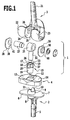
- the knee endoprosthesis 1 shown in the drawing comprises a tibial component 2, a femoral component 3 and a meniscal component 4 arranged between the two.
- the flat top forms a bearing surface 7 for the flat meniscus part 4 on its underside.
- the tibial plate 6 is penetrated by a cylindrical receiving socket 8, whose longitudinal axis is perpendicular to the bearing surface 7 and which projects beyond the bearing surface 7 in the form of an annular flange 9.
- On two opposite sides of this annular flange 9 carries two upwardly projecting projections 10, eleventh
- the meniscal component 4 which in contrast to the metallic tibial component 2 and the metallic femoral component 3 consists of a plastic, in particular of polyethylene, covers substantially the entire bearing surface 7 and has a central, in cross-section circular aperture 12 which abuts with its inner wall the outside of the annular flange 9 tightly abuts, so that the annular flange 9 forms a hinge for the meniscal component 4, this is thus rotatable on the bearing surface 7 about an axis of rotation which coincides with the longitudinal axis of the receiving socket 8.
- a bearing sleeve 15 is inserted from above, which has a cylindrical lower portion 16 and an approximately parallelepiped-shaped head 17. On two opposite sides 18, 19 of the head recesses 20 are incorporated, which are complementary in shape to the projections 10, 11 and open at the bottom.
- the projections 10, 11 enter into the corresponding recesses 20 of the head 17 and thus define the bearing sleeve 15 rotatably in the receiving socket 8.
- the head 17 protrudes above the meniscal component 4 upwards.
- the femur part 3 has in a similar manner as the tibial component 2 on a retaining pin 21 which is inserted into the medullary canal of the femur, and at one end carries two spaced apart and parallel curved sliding surfaces 22, 23 which mounted with knee endoprosthesis in immerse the bearings 13, 14 and support themselves in this.
- the two side walls 24 each have a bearing opening 26 which serve to support a bearing chamber 25 passing transversely through the bearing chamber 27.
- two bearing discs 28, 29 are attached to the bearing shaft 27, these surround the bearing shaft 27 with a laterally projecting from the bearing discs 28, 29 ringflanschförmigen collar 30 which projects into the bearing openings 26 and thus defines the bearing shaft in the bearing openings 26 stops.
- These bearing discs are preferably made of a plastic, for example polyethylene.
- the femur part 3 on the one hand and the tibial component 2 on the other hand are pivotally connected to one another via a hinge joint.
- this hinge joint is displaceable in its height relative to the tibia part 2, since the bearing pin 32 in the bearing sleeve 15 in the axial direction is freely displaceable.
- the distance between femur part 3 and tibia part 2 is determined by the contact of the sliding surfaces 22 and 23 on the bearing shells 13 and 14, respectively.
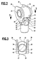
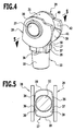
- the head 17 of the bearing sleeve 15 protrudes into the bearing chamber 25 and with its opposite side surfaces 34, 35 the bearing discs 28, 29 opposite ( Figures 2 to 4).
- the side surfaces 34 and 35 of the head 17 are subdivided in the same way in two planar sub-areas, the each extending from the center of the head 17 from obliquely to the sides 18 and 19 of the head 17, in each case two of the opposing faces 36, 37 form stop surfaces, which in a rotation of the femoral part 3 about the defined by the bearing sleeve 15 axis of rotation relative to Tibial 2 strike one of the bearing discs 28 and 29 and thus limit the rotational movement.
- bearing discs 28, 29 are used which have the same thickness along their circumference, this maximum angle of rotation will be the same for all bending angles of the femoral component 3 relative to the tibial component 2, ie from full extension to complete flexion.
- the head 17 facing the inside of the bearing discs 28, 29 then forms in each case a contact surface 38, 39, which abuts one of the partial surfaces 36 or 37 of the head 17.
- bearing plates 28, 29 are first held against rotation about the defined by the bearing shaft 27 pivot axis held on the femur part 3, this can be done by a projection not shown in the drawing on the femur part 3, in a corresponding recess 40 on the circumference of the bearing discs 28th , 29 engages.
- the contact surfaces 38 and 39 of the bearing discs 28 and 29 extend coaxially to the pivot axis of the hinge joint and adjacent to the circumference of the bearing shaft 27, and these contact surfaces 38, 39 are formed in the embodiments of Figures 2 to 5 in the manner of a steadily increasing ramp 41, 42 which increases continuously toward the return 40.
- the direction of the increase and the height of the ramps 41 and 42 are chosen such that when fully extended knee, so in the extended position, the ramps 41 and 42 on the faces 36, 37 of the head 17 abut ( Figures 2 and 3), so that when fully stretched a rotation of the femoral component 3 relative to the tibial component 2 is completely prevented.
- the slope of the ramp 41 is preferably chosen so that it coincides with the inclination of the partial surfaces 36, 37, so that a flat contact is achieved.
- the size of the permitted rotation angle depends on the shape of the ramp 41, 42, which does not necessarily have to be flat in the circumferential direction, but this can vary according to the anatomical conditions, a deviating from a plane course exhibit.
- the design of the ramp allows the designer to determine the size of the maximum angle of rotation as a function of the angle of deflection.
- the ramps 41 and 42 are at the opposite end of the recess 40 in the normal inner surface of the bearing plates 28, 29, so that when fully diffracted, the maximum angle of rotation is released.
- the rotation of the femoral component relative to the tibial component in the extension can be completely prevented and then gradually released with increasing extension up to a maximum angle of rotation. It is always ensured that the sliding surfaces 22, 23 of the femoral component 3 completely remain in the bearing shells 13, 14 of the meniscal component 4, since this is freely rotatably mounted on the tibial component 2 and the respective rotational position of the femoral component 3 adapts easily.
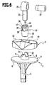
- meniscus parts 4 can be used in different heights.
- meniscus parts 4 are shown in Figures 6 and 7 with two different heights, but it is understood that a larger number of meniscus parts 4 can be used with different heights, so that the surgeon is a kit available from the he can select the meniscus part 4 of the desired height.
- Each meniscus part 4 of a certain height is associated with a bearing sleeve 15 of a certain length, while the bearing sleeves 15 do not differ in the length of the cylindrical lower portion 16, but only in the length of the head 17. This is in accordance with the increase in the height of the meniscal component. 4 extended, so that the bearing sleeve 15 protrudes in all cases the same distance over the top of the meniscal component 4 and thus the bearing shells 13, 14. It is thereby achieved that the bearing pin 32 of the bearing ring 31, regardless of the height of the meniscal component 4 is always equally far immersed in the bearing sleeve 15 and is guided in this in the same way.
- the kit thus includes in addition to the meniscus parts 4 of different heights also a corresponding number of bearing sleeves 15 of different lengths, the length of which is adapted to the different heights of the meniscal parts 4.
Landscapes
- Health & Medical Sciences (AREA)
- Orthopedic Medicine & Surgery (AREA)
- Physical Education & Sports Medicine (AREA)
- Cardiology (AREA)
- Oral & Maxillofacial Surgery (AREA)
- Transplantation (AREA)
- Engineering & Computer Science (AREA)
- Biomedical Technology (AREA)
- Heart & Thoracic Surgery (AREA)
- Vascular Medicine (AREA)
- Life Sciences & Earth Sciences (AREA)
- Animal Behavior & Ethology (AREA)
- General Health & Medical Sciences (AREA)
- Public Health (AREA)
- Veterinary Medicine (AREA)
- Prostheses (AREA)
Applications Claiming Priority (2)
| Application Number | Priority Date | Filing Date | Title |
|---|---|---|---|
| DE200510022584 DE102005022584B4 (de) | 2005-05-09 | 2005-05-09 | Gekoppelte Knieendoprothese |
| DE200510022576 DE102005022576B4 (de) | 2005-05-09 | 2005-05-09 | Modular aufgebaute, gekoppelte Knieendoprothese |
Publications (3)
| Publication Number | Publication Date |
|---|---|
| EP1721585A2 true EP1721585A2 (fr) | 2006-11-15 |
| EP1721585A3 EP1721585A3 (fr) | 2006-12-27 |
| EP1721585B1 EP1721585B1 (fr) | 2012-05-30 |
Family
ID=36779312
Family Applications (1)
| Application Number | Title | Priority Date | Filing Date |
|---|---|---|---|
| EP20060008942 Expired - Lifetime EP1721585B1 (fr) | 2005-05-09 | 2006-04-28 | Prothèse du genou accouplée |
Country Status (2)
| Country | Link |
|---|---|
| EP (1) | EP1721585B1 (fr) |
| ES (1) | ES2385896T3 (fr) |
Cited By (6)
| Publication number | Priority date | Publication date | Assignee | Title |
|---|---|---|---|---|
| WO2013001321A1 (fr) | 2011-06-29 | 2013-01-03 | Mordon Egészségügyi És Innovációs Bt. | Système de prothèse modulaire du genou |
| FR2980104A1 (fr) * | 2011-09-21 | 2013-03-22 | Scor Group | Prothese de genou de type charniere et procede de montage d'une telle prothese |
| US8523950B2 (en) | 2006-06-30 | 2013-09-03 | Smith & Nephew, Inc. | Anatomical motion hinged prosthesis |
| US8545570B2 (en) | 2001-12-21 | 2013-10-01 | Smith & Nephew, Inc. | Hinged joint system |
| WO2013144392A1 (fr) * | 2012-03-29 | 2013-10-03 | Universidad De Málaga | Prothèse de genou à mobilité réglable |
| CN108778192A (zh) * | 2016-03-09 | 2018-11-09 | 沃尔德马连接两合公司 | 关节结构 |
Families Citing this family (1)
| Publication number | Priority date | Publication date | Assignee | Title |
|---|---|---|---|---|
| DE102015010221B4 (de) | 2014-09-05 | 2017-11-16 | Carl Haasper | Kniegelenk-Endoprothese |
Family Cites Families (4)
| Publication number | Priority date | Publication date | Assignee | Title |
|---|---|---|---|---|
| US5370701A (en) * | 1990-09-28 | 1994-12-06 | Arch Development Corporation | Rotating/sliding contrained prosthetic knee |
| US5824096A (en) * | 1994-12-12 | 1998-10-20 | Biomedical Engineering Trust I | Hinged knee prosthesis with condylar bearing |
| FR2771283B1 (fr) * | 1997-11-24 | 2000-03-03 | Implants & Instr Chirurg | Implant tibial pour prothese du genou |
| US6773461B2 (en) * | 2001-01-29 | 2004-08-10 | Zimmer Technology, Inc. | Constrained prosthetic knee with rotating bearing |
-
2006
- 2006-04-28 EP EP20060008942 patent/EP1721585B1/fr not_active Expired - Lifetime
- 2006-04-28 ES ES06008942T patent/ES2385896T3/es not_active Expired - Lifetime
Cited By (12)
| Publication number | Priority date | Publication date | Assignee | Title |
|---|---|---|---|---|
| US8545570B2 (en) | 2001-12-21 | 2013-10-01 | Smith & Nephew, Inc. | Hinged joint system |
| US9056012B2 (en) | 2001-12-21 | 2015-06-16 | Smith & Nephew, Inc. | Hinged joint system |
| US9693868B2 (en) | 2001-12-21 | 2017-07-04 | Smith & Nephew, Inc. | Hinged joint system |
| US8523950B2 (en) | 2006-06-30 | 2013-09-03 | Smith & Nephew, Inc. | Anatomical motion hinged prosthesis |
| US9730799B2 (en) | 2006-06-30 | 2017-08-15 | Smith & Nephew, Inc. | Anatomical motion hinged prosthesis |
| US10779949B2 (en) | 2006-06-30 | 2020-09-22 | Smith & Nephew, Inc. | Anatomical motion hinged prosthesis |
| US12383405B2 (en) | 2006-06-30 | 2025-08-12 | Smith & Nephew, Inc. | Anatomical motion hinged prosthesis |
| WO2013001321A1 (fr) | 2011-06-29 | 2013-01-03 | Mordon Egészségügyi És Innovációs Bt. | Système de prothèse modulaire du genou |
| FR2980104A1 (fr) * | 2011-09-21 | 2013-03-22 | Scor Group | Prothese de genou de type charniere et procede de montage d'une telle prothese |
| WO2013144392A1 (fr) * | 2012-03-29 | 2013-10-03 | Universidad De Málaga | Prothèse de genou à mobilité réglable |
| ES2429390R1 (es) * | 2012-03-29 | 2014-02-17 | Servicio Andaluz De Salud | Prótesis de rodilla con movilidad regulable |
| CN108778192A (zh) * | 2016-03-09 | 2018-11-09 | 沃尔德马连接两合公司 | 关节结构 |
Also Published As
| Publication number | Publication date |
|---|---|
| EP1721585A3 (fr) | 2006-12-27 |
| EP1721585B1 (fr) | 2012-05-30 |
| ES2385896T3 (es) | 2012-08-02 |
Similar Documents
| Publication | Publication Date | Title |
|---|---|---|
| DE4102509C2 (de) | Kniegelenkendoprothese | |
| EP1539051B1 (fr) | Implant comprenant une articulation en deux parties | |
| EP1598034B1 (fr) | Ancrage glénoIde | |
| EP1575457B1 (fr) | Implant intervertebral | |
| EP1325718B1 (fr) | Elément tibial pour une prothèse de remplacement du genou | |
| EP3137017B1 (fr) | Endoprothèse pour l'articulation du genou | |
| DE2614170C2 (de) | Verbund-Endoprothese | |
| EP1572037A1 (fr) | Implant intervertebral comprenant des pieces d'articulation basculantes | |
| DE2907524A1 (de) | Prothesengelenk | |
| EP3370653B1 (fr) | Endoprothèse de l'articulation du genou | |
| EP1721585B1 (fr) | Prothèse du genou accouplée | |
| EP1408887A1 (fr) | Endoprothese pour articulation du genou | |
| EP1721584B1 (fr) | Endoprothèse de genou avec une charnière à flexion | |
| DE102019106599A1 (de) | Kniegelenkendoprothesenvorrichtung und Kniegelenkendoprothese | |
| DE102005022584B4 (de) | Gekoppelte Knieendoprothese | |
| DE202005007685U1 (de) | Gekoppelte Knieendoprothese | |
| DE29514169U1 (de) | Prothese für den Ersatz eines Gelenks | |
| EP1809216B1 (fr) | Articulation à charnière stable au basculement et composant orthopédique monté avec une telle articulation | |
| DE10058372C2 (de) | Gelenkprothese | |
| WO2018087246A1 (fr) | Implant présentant un insert annulaire | |
| DE9216202U1 (de) | Prothese für den Ersatz eines Finger-Mittelgelenks | |
| EP0915681B1 (fr) | Instrument tubulaire du type trocart | |
| DE102005022576B4 (de) | Modular aufgebaute, gekoppelte Knieendoprothese | |
| EP2508149B1 (fr) | Système d'endoprothèse de genou | |
| DE202005007684U1 (de) | Modular aufgebaute, gekoppelte Knieendoprothese |
Legal Events
| Date | Code | Title | Description |
|---|---|---|---|
| PUAI | Public reference made under article 153(3) epc to a published international application that has entered the european phase |
Free format text: ORIGINAL CODE: 0009012 |
|
| AK | Designated contracting states |
Kind code of ref document: A2 Designated state(s): AT BE BG CH CY CZ DE DK EE ES FI FR GB GR HU IE IS IT LI LT LU LV MC NL PL PT RO SE SI SK TR |
|
| AX | Request for extension of the european patent |
Extension state: AL BA HR MK YU |
|
| PUAL | Search report despatched |
Free format text: ORIGINAL CODE: 0009013 |
|
| AK | Designated contracting states |
Kind code of ref document: A3 Designated state(s): AT BE BG CH CY CZ DE DK EE ES FI FR GB GR HU IE IS IT LI LT LU LV MC NL PL PT RO SE SI SK TR |
|
| AX | Request for extension of the european patent |
Extension state: AL BA HR MK YU |
|
| 17P | Request for examination filed |
Effective date: 20070503 |
|
| AKX | Designation fees paid |
Designated state(s): AT BE BG CH CY CZ DE DK EE ES FI FR GB GR HU IE IS IT LI LT LU LV MC NL PL PT RO SE SI SK TR |
|
| RAP1 | Party data changed (applicant data changed or rights of an application transferred) |
Owner name: AESCULAP AG & CO. KG Owner name: REIGNIER, BERNARD |
|
| RAP1 | Party data changed (applicant data changed or rights of an application transferred) |
Owner name: REIGNIER, BERNARD Owner name: AESCULAP AG |
|
| GRAP | Despatch of communication of intention to grant a patent |
Free format text: ORIGINAL CODE: EPIDOSNIGR1 |
|
| GRAS | Grant fee paid |
Free format text: ORIGINAL CODE: EPIDOSNIGR3 |
|
| GRAA | (expected) grant |
Free format text: ORIGINAL CODE: 0009210 |
|
| AK | Designated contracting states |
Kind code of ref document: B1 Designated state(s): AT BE BG CH CY CZ DE DK EE ES FI FR GB GR HU IE IS IT LI LT LU LV MC NL PL PT RO SE SI SK TR |
|
| REG | Reference to a national code |
Ref country code: GB Ref legal event code: FG4D Free format text: NOT ENGLISH |
|
| REG | Reference to a national code |
Ref country code: CH Ref legal event code: EP |
|
| REG | Reference to a national code |
Ref country code: AT Ref legal event code: REF Ref document number: 559687 Country of ref document: AT Kind code of ref document: T Effective date: 20120615 |
|
| REG | Reference to a national code |
Ref country code: IE Ref legal event code: FG4D Free format text: LANGUAGE OF EP DOCUMENT: GERMAN |
|
| REG | Reference to a national code |
Ref country code: CH Ref legal event code: NV Representative=s name: ISLER & PEDRAZZINI AG |
|
| REG | Reference to a national code |
Ref country code: DE Ref legal event code: R096 Ref document number: 502006011496 Country of ref document: DE Effective date: 20120802 Ref country code: ES Ref legal event code: FG2A Ref document number: 2385896 Country of ref document: ES Kind code of ref document: T3 Effective date: 20120802 |
|
| REG | Reference to a national code |
Ref country code: NL Ref legal event code: VDEP Effective date: 20120530 |
|
| REG | Reference to a national code |
Ref country code: LT Ref legal event code: MG4D Effective date: 20120530 |
|
| PG25 | Lapsed in a contracting state [announced via postgrant information from national office to epo] |
Ref country code: FI Free format text: LAPSE BECAUSE OF FAILURE TO SUBMIT A TRANSLATION OF THE DESCRIPTION OR TO PAY THE FEE WITHIN THE PRESCRIBED TIME-LIMIT Effective date: 20120530 Ref country code: LT Free format text: LAPSE BECAUSE OF FAILURE TO SUBMIT A TRANSLATION OF THE DESCRIPTION OR TO PAY THE FEE WITHIN THE PRESCRIBED TIME-LIMIT Effective date: 20120530 Ref country code: SE Free format text: LAPSE BECAUSE OF FAILURE TO SUBMIT A TRANSLATION OF THE DESCRIPTION OR TO PAY THE FEE WITHIN THE PRESCRIBED TIME-LIMIT Effective date: 20120530 Ref country code: IS Free format text: LAPSE BECAUSE OF FAILURE TO SUBMIT A TRANSLATION OF THE DESCRIPTION OR TO PAY THE FEE WITHIN THE PRESCRIBED TIME-LIMIT Effective date: 20120930 Ref country code: CY Free format text: LAPSE BECAUSE OF FAILURE TO SUBMIT A TRANSLATION OF THE DESCRIPTION OR TO PAY THE FEE WITHIN THE PRESCRIBED TIME-LIMIT Effective date: 20120530 |
|
| PG25 | Lapsed in a contracting state [announced via postgrant information from national office to epo] |
Ref country code: GR Free format text: LAPSE BECAUSE OF FAILURE TO SUBMIT A TRANSLATION OF THE DESCRIPTION OR TO PAY THE FEE WITHIN THE PRESCRIBED TIME-LIMIT Effective date: 20120831 Ref country code: SI Free format text: LAPSE BECAUSE OF FAILURE TO SUBMIT A TRANSLATION OF THE DESCRIPTION OR TO PAY THE FEE WITHIN THE PRESCRIBED TIME-LIMIT Effective date: 20120530 Ref country code: LV Free format text: LAPSE BECAUSE OF FAILURE TO SUBMIT A TRANSLATION OF THE DESCRIPTION OR TO PAY THE FEE WITHIN THE PRESCRIBED TIME-LIMIT Effective date: 20120530 |
|
| PG25 | Lapsed in a contracting state [announced via postgrant information from national office to epo] |
Ref country code: EE Free format text: LAPSE BECAUSE OF FAILURE TO SUBMIT A TRANSLATION OF THE DESCRIPTION OR TO PAY THE FEE WITHIN THE PRESCRIBED TIME-LIMIT Effective date: 20120530 Ref country code: CZ Free format text: LAPSE BECAUSE OF FAILURE TO SUBMIT A TRANSLATION OF THE DESCRIPTION OR TO PAY THE FEE WITHIN THE PRESCRIBED TIME-LIMIT Effective date: 20120530 Ref country code: NL Free format text: LAPSE BECAUSE OF FAILURE TO SUBMIT A TRANSLATION OF THE DESCRIPTION OR TO PAY THE FEE WITHIN THE PRESCRIBED TIME-LIMIT Effective date: 20120530 Ref country code: RO Free format text: LAPSE BECAUSE OF FAILURE TO SUBMIT A TRANSLATION OF THE DESCRIPTION OR TO PAY THE FEE WITHIN THE PRESCRIBED TIME-LIMIT Effective date: 20120530 Ref country code: DK Free format text: LAPSE BECAUSE OF FAILURE TO SUBMIT A TRANSLATION OF THE DESCRIPTION OR TO PAY THE FEE WITHIN THE PRESCRIBED TIME-LIMIT Effective date: 20120530 Ref country code: SK Free format text: LAPSE BECAUSE OF FAILURE TO SUBMIT A TRANSLATION OF THE DESCRIPTION OR TO PAY THE FEE WITHIN THE PRESCRIBED TIME-LIMIT Effective date: 20120530 |
|
| PG25 | Lapsed in a contracting state [announced via postgrant information from national office to epo] |
Ref country code: PT Free format text: LAPSE BECAUSE OF FAILURE TO SUBMIT A TRANSLATION OF THE DESCRIPTION OR TO PAY THE FEE WITHIN THE PRESCRIBED TIME-LIMIT Effective date: 20121001 Ref country code: PL Free format text: LAPSE BECAUSE OF FAILURE TO SUBMIT A TRANSLATION OF THE DESCRIPTION OR TO PAY THE FEE WITHIN THE PRESCRIBED TIME-LIMIT Effective date: 20120530 |
|
| PLBE | No opposition filed within time limit |
Free format text: ORIGINAL CODE: 0009261 |
|
| STAA | Information on the status of an ep patent application or granted ep patent |
Free format text: STATUS: NO OPPOSITION FILED WITHIN TIME LIMIT |
|
| 26N | No opposition filed |
Effective date: 20130301 |
|
| REG | Reference to a national code |
Ref country code: DE Ref legal event code: R097 Ref document number: 502006011496 Country of ref document: DE Effective date: 20130301 |
|
| PG25 | Lapsed in a contracting state [announced via postgrant information from national office to epo] |
Ref country code: BG Free format text: LAPSE BECAUSE OF FAILURE TO SUBMIT A TRANSLATION OF THE DESCRIPTION OR TO PAY THE FEE WITHIN THE PRESCRIBED TIME-LIMIT Effective date: 20120830 |
|
| BERE | Be: lapsed |
Owner name: REIGNIER, BERNARD Effective date: 20130430 Owner name: AESCULAP A.G. Effective date: 20130430 |
|
| PG25 | Lapsed in a contracting state [announced via postgrant information from national office to epo] |
Ref country code: MC Free format text: LAPSE BECAUSE OF FAILURE TO SUBMIT A TRANSLATION OF THE DESCRIPTION OR TO PAY THE FEE WITHIN THE PRESCRIBED TIME-LIMIT Effective date: 20120530 |
|
| REG | Reference to a national code |
Ref country code: IE Ref legal event code: MM4A |
|
| PG25 | Lapsed in a contracting state [announced via postgrant information from national office to epo] |
Ref country code: BE Free format text: LAPSE BECAUSE OF NON-PAYMENT OF DUE FEES Effective date: 20130430 |
|
| PG25 | Lapsed in a contracting state [announced via postgrant information from national office to epo] |
Ref country code: IE Free format text: LAPSE BECAUSE OF NON-PAYMENT OF DUE FEES Effective date: 20130428 |
|
| REG | Reference to a national code |
Ref country code: AT Ref legal event code: MM01 Ref document number: 559687 Country of ref document: AT Kind code of ref document: T Effective date: 20130428 |
|
| PG25 | Lapsed in a contracting state [announced via postgrant information from national office to epo] |
Ref country code: AT Free format text: LAPSE BECAUSE OF NON-PAYMENT OF DUE FEES Effective date: 20130428 |
|
| PG25 | Lapsed in a contracting state [announced via postgrant information from national office to epo] |
Ref country code: TR Free format text: LAPSE BECAUSE OF FAILURE TO SUBMIT A TRANSLATION OF THE DESCRIPTION OR TO PAY THE FEE WITHIN THE PRESCRIBED TIME-LIMIT Effective date: 20120530 |
|
| REG | Reference to a national code |
Ref country code: DE Ref legal event code: R082 Ref document number: 502006011496 Country of ref document: DE Representative=s name: HOEGER, STELLRECHT & PARTNER PATENTANWAELTE MB, DE |
|
| PG25 | Lapsed in a contracting state [announced via postgrant information from national office to epo] |
Ref country code: HU Free format text: LAPSE BECAUSE OF FAILURE TO SUBMIT A TRANSLATION OF THE DESCRIPTION OR TO PAY THE FEE WITHIN THE PRESCRIBED TIME-LIMIT; INVALID AB INITIO Effective date: 20060428 Ref country code: LU Free format text: LAPSE BECAUSE OF NON-PAYMENT OF DUE FEES Effective date: 20130428 |
|
| REG | Reference to a national code |
Ref country code: FR Ref legal event code: PLFP Year of fee payment: 11 |
|
| REG | Reference to a national code |
Ref country code: FR Ref legal event code: PLFP Year of fee payment: 12 |
|
| REG | Reference to a national code |
Ref country code: FR Ref legal event code: PLFP Year of fee payment: 13 |
|
| REG | Reference to a national code |
Ref country code: DE Ref legal event code: R082 Ref document number: 502006011496 Country of ref document: DE Representative=s name: HOEGER, STELLRECHT & PARTNER PATENTANWAELTE MB, DE |
|
| PGFP | Annual fee paid to national office [announced via postgrant information from national office to epo] |
Ref country code: IT Payment date: 20230428 Year of fee payment: 18 Ref country code: FR Payment date: 20230417 Year of fee payment: 18 Ref country code: ES Payment date: 20230517 Year of fee payment: 18 Ref country code: DE Payment date: 20230418 Year of fee payment: 18 Ref country code: CH Payment date: 20230502 Year of fee payment: 18 |
|
| PGFP | Annual fee paid to national office [announced via postgrant information from national office to epo] |
Ref country code: GB Payment date: 20230420 Year of fee payment: 18 |
|
| REG | Reference to a national code |
Ref country code: DE Ref legal event code: R119 Ref document number: 502006011496 Country of ref document: DE |
|
| REG | Reference to a national code |
Ref country code: CH Ref legal event code: PL |
|
| GBPC | Gb: european patent ceased through non-payment of renewal fee |
Effective date: 20240428 |
|
| PG25 | Lapsed in a contracting state [announced via postgrant information from national office to epo] |
Ref country code: DE Free format text: LAPSE BECAUSE OF NON-PAYMENT OF DUE FEES Effective date: 20241105 |
|
| PG25 | Lapsed in a contracting state [announced via postgrant information from national office to epo] |
Ref country code: GB Free format text: LAPSE BECAUSE OF NON-PAYMENT OF DUE FEES Effective date: 20240428 |
|
| PG25 | Lapsed in a contracting state [announced via postgrant information from national office to epo] |
Ref country code: FR Free format text: LAPSE BECAUSE OF NON-PAYMENT OF DUE FEES Effective date: 20240430 |
|
| PG25 | Lapsed in a contracting state [announced via postgrant information from national office to epo] |
Ref country code: GB Free format text: LAPSE BECAUSE OF NON-PAYMENT OF DUE FEES Effective date: 20240428 Ref country code: FR Free format text: LAPSE BECAUSE OF NON-PAYMENT OF DUE FEES Effective date: 20240430 Ref country code: DE Free format text: LAPSE BECAUSE OF NON-PAYMENT OF DUE FEES Effective date: 20241105 Ref country code: CH Free format text: LAPSE BECAUSE OF NON-PAYMENT OF DUE FEES Effective date: 20240430 |
|
| PG25 | Lapsed in a contracting state [announced via postgrant information from national office to epo] |
Ref country code: IT Free format text: LAPSE BECAUSE OF NON-PAYMENT OF DUE FEES Effective date: 20240428 |
|
| REG | Reference to a national code |
Ref country code: ES Ref legal event code: FD2A Effective date: 20250602 |
|
| PG25 | Lapsed in a contracting state [announced via postgrant information from national office to epo] |
Ref country code: ES Free format text: LAPSE BECAUSE OF NON-PAYMENT OF DUE FEES Effective date: 20240429 |