EP1721792B1 - Fernbedienungssystem für Kraftfahrzeug mit Beschleunigungssensor und/oder Drucksensor - Google Patents
Fernbedienungssystem für Kraftfahrzeug mit Beschleunigungssensor und/oder Drucksensor Download PDFInfo
- Publication number
- EP1721792B1 EP1721792B1 EP05291009A EP05291009A EP1721792B1 EP 1721792 B1 EP1721792 B1 EP 1721792B1 EP 05291009 A EP05291009 A EP 05291009A EP 05291009 A EP05291009 A EP 05291009A EP 1721792 B1 EP1721792 B1 EP 1721792B1
- Authority
- EP
- European Patent Office
- Prior art keywords
- sensor
- vehicle
- identification device
- signal
- acceleration
- Prior art date
- Legal status (The legal status is an assumption and is not a legal conclusion. Google has not performed a legal analysis and makes no representation as to the accuracy of the status listed.)
- Expired - Lifetime
Links
Images




Classifications
-
- B—PERFORMING OPERATIONS; TRANSPORTING
- B60—VEHICLES IN GENERAL
- B60R—VEHICLES, VEHICLE FITTINGS, OR VEHICLE PARTS, NOT OTHERWISE PROVIDED FOR
- B60R25/00—Fittings or systems for preventing or indicating unauthorised use or theft of vehicles
- B60R25/20—Means to switch the anti-theft system on or off
- B60R25/24—Means to switch the anti-theft system on or off using electronic identifiers containing a code not memorised by the user
-
- G—PHYSICS
- G07—CHECKING-DEVICES
- G07C—TIME OR ATTENDANCE REGISTERS; REGISTERING OR INDICATING THE WORKING OF MACHINES; GENERATING RANDOM NUMBERS; VOTING OR LOTTERY APPARATUS; ARRANGEMENTS, SYSTEMS OR APPARATUS FOR CHECKING NOT PROVIDED FOR ELSEWHERE
- G07C9/00—Individual registration on entry or exit
- G07C9/00174—Electronically operated locks; Circuits therefor; Nonmechanical keys therefor, e.g. passive or active electrical keys or other data carriers without mechanical keys
- G07C9/00309—Electronically operated locks; Circuits therefor; Nonmechanical keys therefor, e.g. passive or active electrical keys or other data carriers without mechanical keys operated with bidirectional data transmission between data carrier and locks
-
- G—PHYSICS
- G07—CHECKING-DEVICES
- G07C—TIME OR ATTENDANCE REGISTERS; REGISTERING OR INDICATING THE WORKING OF MACHINES; GENERATING RANDOM NUMBERS; VOTING OR LOTTERY APPARATUS; ARRANGEMENTS, SYSTEMS OR APPARATUS FOR CHECKING NOT PROVIDED FOR ELSEWHERE
- G07C9/00—Individual registration on entry or exit
- G07C9/00174—Electronically operated locks; Circuits therefor; Nonmechanical keys therefor, e.g. passive or active electrical keys or other data carriers without mechanical keys
- G07C2009/00753—Electronically operated locks; Circuits therefor; Nonmechanical keys therefor, e.g. passive or active electrical keys or other data carriers without mechanical keys operated by active electrical keys
- G07C2009/00769—Electronically operated locks; Circuits therefor; Nonmechanical keys therefor, e.g. passive or active electrical keys or other data carriers without mechanical keys operated by active electrical keys with data transmission performed by wireless means
- G07C2009/00793—Electronically operated locks; Circuits therefor; Nonmechanical keys therefor, e.g. passive or active electrical keys or other data carriers without mechanical keys operated by active electrical keys with data transmission performed by wireless means by Hertzian waves
-
- G—PHYSICS
- G07—CHECKING-DEVICES
- G07C—TIME OR ATTENDANCE REGISTERS; REGISTERING OR INDICATING THE WORKING OF MACHINES; GENERATING RANDOM NUMBERS; VOTING OR LOTTERY APPARATUS; ARRANGEMENTS, SYSTEMS OR APPARATUS FOR CHECKING NOT PROVIDED FOR ELSEWHERE
- G07C2209/00—Indexing scheme relating to groups G07C9/00 - G07C9/38
- G07C2209/60—Indexing scheme relating to groups G07C9/00174 - G07C9/00944
- G07C2209/63—Comprising locating means for detecting the position of the data carrier, i.e. within the vehicle or within a certain distance from the vehicle
Definitions
- the present invention relates to a so-called hands-free control system for a vehicle. More particularly, the present invention relates to a system adapted to authorize or prevent the starting of a vehicle and / or to control means for locking / unlocking the locks of the vehicle doors according to the location of an identification device. inside or outside the interior of the vehicle.
- the interior space of the vehicle includes any space defined by walls, this space may be habitable, as the passenger compartment, or not habitable, as the trunk.
- the invention also applies to so-called minivan vehicles in which the boot and the living space are not separated.
- Vehicles which are equipped with a hands-free control system of the type above.
- the term "hands-free” means that it is not necessary to use a mechanical key to perform certain operations.
- the hands-free control system makes it possible to implement a hands-free access method for remotely controlling a locking member for access to the vehicle, for example a door lock or trunk lid, or a hands-free starting method for remotely controlling a vehicle starting member.
- the identification device is an electronic identifier, which is a transceiver intended to be worn by an authorized user of the vehicle and which replaces the mechanical key.
- a central control unit on the vehicle establishes a two-way remote dialogue with the portable receiver device to authenticate the user and control means for locking / unlocking the locks of the doors, respectively the means for starting the engine, when the user has been recognized as genuine.
- the initialization of the communication protocol can be activated by touching or actuating the outside door handle, or by detecting the presence of the hand in the vicinity of the outside door handle, for hands-free access; or by pressing a start button on the dashboard, for hands-free startup.
- this initialization can be triggered by operating a control button of the portable receiver device.
- a modulated magnetic field For the connection from the central control unit to the portable receiver device, it is common to use a modulated magnetic field, with a carrier frequency of, for example, between 10 kHz and 20 kHz, or around 125 kHz, around 6 MHz or around 13 MHz, depending on the authorized bands.
- EP-1 363 354-A1 discloses a hands-free access system, in which a loop antenna delimits a detection zone corresponding to the interior space of a vehicle.
- the portable identification device measures the amplitude of the field emitted by the loop antenna, which makes it possible to determine whether the identification device is in the detection zone or not.
- This hands-free access system has several disadvantages.
- the amplitude of the field emitted by the loop antenna in the vicinity of the periphery of the detection zone is substantially equal to the inside and outside of the detection zone. It is therefore not always possible to locate the identification device reliably.
- the detection area is large, it is necessary to provide several loop antennas or an antenna forming several loops, which complicates the system and increases the work necessary for installation on a vehicle.
- the carrier frequency used must be compatible with the loop antenna.
- Hands-free access systems must be protected from hacking, including relay box piracy.
- the principle of relay box piracy is known and recalled by EP-1 152 107-A1 .
- This document describes a hands-free access system protected from relay box piracy by measuring a time offset between two signals. This system requires the use of an expensive electronic device for time shift measurement.
- the radio communication must be done at high frequency, of the order of a few hundred MHz, which implies constraints on the antennas that can be used. At short distances, this solution may exhibit unpredictable behaviors because of the multipath propagation of such high frequency waves.
- infrasound sensor is known for intrusion detection.
- WO 95/06925 describes an intrusion detection device in a vehicle by infrasound measurement. This device is intended to detect the intrusion of a thief. It does not make it possible to determine whether a user wearing an identification device is inside or outside the vehicle.
- the document DE 100 52 451 describes a system according to the preamble of claim 1.
- This document DE 19850176 describes a system in which the same physical quantity is measured on the one hand in the transponder and on the other hand in the vehicle.
- an object of the invention is to provide a hands-free control system for determining the location of an identification device inside or outside the inner space reliably.
- Another object of the invention is to provide a hands-free control system which is protected from piracy by relay box.
- the invention provides a so-called hands-free control system for a vehicle according to claim 1.
- the identification device if it is inside the vehicle, it will undergo movements strongly correlated to the movements of the vehicle. These movements are for example caused by starting the engine of the vehicle, or by sagging suspensions of the vehicle following the entry of a person into the vehicle. The accelerations measured by the first and second sensors will therefore be highly correlated.
- the identification device If, on the contrary, the identification device is not inside the vehicle, it will undergo movements independent of the movements of the vehicle. For example, he will experience the movements of the person carrying the identification device, while the vehicle is stationary or is subject to slight vibrations caused by the movement of objects in its environment. The accelerations measured by the first and second sensors will therefore be independent and uncorrelated.
- the comparison of the measurement signal and the reference signal therefore makes it possible to determine whether the identification device is in the vehicle.
- Relay box piracy of this system is impossible. Indeed, it would involve measuring the movements of the vehicle and creating movements corresponding to the level of the identification device, worn by the user, which necessarily implies a cumbersome and visible mechanical device, therefore incompatible with the discretion necessary for hackers. In addition, the user would perceive the movements.
- the first sensor is capable of measuring an angular acceleration, the measurement signal depending on the modulus of the rotation vector supplied by the first sensor, the second sensor being able to measure an angular acceleration, the reference signal depending on the module of a rotation vector provided by the second sensor.
- the first sensor is able to measure a linear acceleration in at least one direction, the measurement signal depending on the modulus of an acceleration vector supplied by the first sensor, the second sensor being able to measure a linear acceleration according to FIG. least one direction, the signal of module-dependent reference of an acceleration vector provided by the second sensor.
- the modulus of the rotation vector or the acceleration vector makes it possible to observe a correlation between the movements of the identification device and the movements of the vehicle, even when the orientation of the first sensor does not correspond to that of the vehicle. second sensor.
- the comparator comprises a memory, said comparator being able to store said measurement signal and said reference signal in said memory during at least one comparison period.
- said central unit is adapted to be connected to a sensor for receiving a trigger signal from said sensor, said comparator being able to store said measurement signal and said reference signal during a comparison period beginning substantially on receipt of said signal. trigger.
- said sensor producing said trigger signal is a door handle sensor responsive to the actuation of a door handle.
- said sensor producing said trigger signal is an actuation button for controlling the starting of said vehicle.
- the system comprises an actuation button for controlling the starting of said vehicle, said comparator being able to store said measurement signal and said reference signal during a comparison period ending after the actuation of said actuation button.
- said central unit is able to detect the starting of an engine of said vehicle, said comparator being able to store said measurement signal and said reference signal during a comparison period ending after said start.
- said comparator is able to determine a correlation level between a temporal envelope of said measurement signal and a temporal envelope of said reference signal, said locating means being able to determine the location of said identification device to inside or outside said vehicle according to said correlation level.
- said identification device comprises a pressure sensor able to measure pressure variations in the environment of said identification device in an infrasound frequency range, said transmitter of the identification device being able to transmit a signal of response dependent on said pressure variations measured by said sensor to said central unit, said comparator being adapted to compare said response signal with a pressure reference signal to which pressure variations in said interior space are correlated in an infrasonic frequency range so as to determining the location of said identification device inside or outside said interior space.
- said control system comprises a combined pressure and acceleration sensor constituting said first sensor and said pressure sensor and whose combined measurement signal constitutes said measurement signal and said response signal, said second sensor being a second sensor combined pressure and acceleration device for measuring pressure variations in an interior space of said vehicle in an infrasound frequency range, said reference signal and said pressure reference signal consisting of a single reference signal measured by said second combined pressure and acceleration sensor.
- the invention also provides a method of controlling a so-called hands-free control system for a vehicle according to claim 16.
- the figure 1 shows a vehicle 1 that includes a wall 2 delimiting an interior space 3.
- the wall 2 comprises for example the roof, the floor, the doors, the windows, etc. of the vehicle 1.
- infrasound frequency domain is understood to mean inaudible frequencies for a human, that is to say less than 40 Hz. These vibrations are caused by all kinds of events occurring in or out of the vehicle, for example by the movement of persons or objects in the vehicle environment, or by wind.
- the wall 2 is not perfectly insulating to infrasonic vibrations, but leaks schematically by the openings 4. However, when all the opening of the vehicle 1 (doors, trunk lid, sunroof, etc.) are closed, these leaks are very weak. Thus, under these conditions, the wall 2 forms a good screen for the transmission of pressure variations between the outside of the vehicle 1 and the interior space 3. Thus, pressure variations in a frequency range infrasound in space interior 3 are very different from those outside the vehicle 1.
- the vehicle 1 is equipped with a hands-free control system.
- the hands-free control system comprises a central unit 5 embedded in the vehicle 1 and an identification device 6 intended to be worn by a user of the vehicle.
- the identification device 6 is represented twice: once in the interior space 3 and once outside the vehicle 1, close to the wall 2.
- the central unit 5 comprises a transmitter / receiver (not shown) connected to an antenna 7 on board the vehicle 1.
- the identification device comprises a controller 9 which comprises a transmitter / receiver connected to an antenna 8 integrated in the device. identification 6.
- the central unit 5 and the identification device 6 are able to establish a bidirectional electromagnetic communication, represented by the double arrow 10, to exchange messages.
- a triggering event such as the fact that a user has touched the handle of one of the doors of the vehicle 1
- the central unit exchanges messages with the identification device according to a known cryptographic method, to authenticate the identification device.
- the carrier frequency of the communication 10 is for example 125 kHz for the connection from the central unit 5 to the identification device 6, and 13 MHz for the connection from the identification device 6 to the central unit 5.
- the identification device comprises an infrasonic sensor 11.
- the infrasonic sensor 11 is able to measure pressure variations in the environment of the identification device 6 in an infrasound frequency range.
- the sensor 11 comprises for example an electret effect microphone.
- the sensor 11 transmits a measurement signal to the controller 9.
- the controller 9 comprises an analog / digital converter capable of sampling and digitizing the measurement signal.
- the transmitter / receiver of the controller 9 is able to transmit to the central unit 5 a response signal which corresponds to the sampled and digitized measurement signal, via the electromagnetic communication 10.
- the response signal is transmitted in encrypted manner using a key previously exchanged between the central unit 5 and the identification device 6.
- the measurement signal emitted by the infrasonic sensor 11 could be transmitted to the central unit 5 in an analog manner, for example in the form of a response signal modulating the carrier of the communication. 10.
- the hands-free control system also comprises an infrasonic internal sensor 12, arranged in the interior space 3, and an external infrasonic sensor 13, embedded on the vehicle 1 and arranged outside the interior space 3.
- the sensors 12 and 13 are preferably fixed by means of decoupling means, for example elastomeric supports, in order to sufficiently decouple the sensors 12 and 13 from the vehicle structure. This prevents the structure transmitting to the sensor 12, respectively 13, the vibrations produced outside the vehicle 1, respectively inside the vehicle 1.
- the sensors 12 and 13 are connected to the central unit 5. They are for example identical to the sensor 11.
- the central unit 5 thus has an internal reference signal P i , coming from the sensor 12, an external reference signal P e , coming from the sensor 13, and a measurement signal P m , coming from of the sensor 11.
- the pressure variations in an infrasound frequency range in the interior space 3 are very different from those outside the vehicle 1.
- the identification device 6 is in the space inside 3, the measurement signal is very different from the external reference signal and very similar to, or identical to, the internal reference signal.
- the measurement signal is very different from the internal reference signal and very similar to, or identical to, the external reference signal.
- the central unit 5 is able to determine the location of the identification device inside or outside the interior space 3 and can authorize or prevent the vehicle starting 1 and / or control means for locking / unlocking the locks of the doors of the vehicle 1 according to this location.
- the central processing unit 5 comprises calculation means able to determine, on the one hand, the rms value of the difference between the internal reference signal P i and the measurement signal P m , and on the other hand the rms value.
- the sensors 11, 12 and 13 may for example provide a signal proportional to the pressure variations they measure, or a signal proportional to the time derivative of these pressure variations. It is equivalent to know a signal itself or its derivative.
- the comparison operation may relate to the reference and measurement signals themselves, proportional to the time derivatives of the measured pressure variations, or to these signals after integration.
- An active mode-1 is described with reference to Figures 2 to 5 .
- the elements that are the same or similar to passive mode elements are designated by the same reference numerals, increased by 100.
- the vehicle 101 comprises a wall 102 delimiting an interior space 103 and having leaks 104.
- a hands-free control system comprises a central unit 105 capable of establishing an electromagnetic communication 110 with an identification device 106. to antennas 107, 108.
- the identification device 106 includes an infrasonic pressure sensor 111 and a controller 109. The differences between the passive mode and the active mode-1 are explained below.
- Active-1 control system does not have an indoor or outdoor pressure sensor.
- the central unit 105 is connected to two speakers 120 via a not shown output interface. Alternatively it could be connected to one or more than two speakers.
- the loudspeakers 120 are the speakers of the car radio of the vehicle 101. Alternatively, these are speakers specific to the hands-free control system.
- the loudspeakers 120 are able to generate pressure variations in the interior space 103, under the control of the central unit 105.
- the figure 3 is a more detailed representation of the CPU 105 and the identification device 106.
- the functional aspects of the CPU 105 and the identification device are described below.
- the elements that fulfill these functions may be embodied as a specifically programmed generic electronic circuit, a specific electronic circuit, or a combination of both. They can be done centrally or distributed. This also applies to the corresponding elements of the other embodiments.
- the central unit 121 includes a random number generator 121.
- This generator 121 generates a random number, for example a binary word of sixteen bits Sb t, and stores it.
- the generator 121 sends a binary signal A corresponding to the word Sb t to a shaping circuit 122.
- the shaping circuit 122 changes the coding of the binary word Sb t . More precisely, it transforms the signal A in which the "0" and "1" are represented for example by the voltages + 1V and -1V respectively, in a B signal of the type No Return to Zero (NRZ), which presents a zero average.
- NRZ No Return to Zero
- the signal B is filtered by a low-pass filter 123 which passes only infrasound frequencies, and whose output signal C is applied, via an amplifier 124, to the speakers 120.
- the bits are transmitted at a speed preferably between 10 and 40 bits per second. For example, at a speed of 20 bits per second, it takes 0.8 seconds to transmit the six bit binary word Sb t .
- the shaping circuit 122 makes it possible to obtain, from the signal A, a signal C of zero average value.
- the control signal of the loudspeakers 120 does not have a DC component, which prevents the membranes of the loudspeakers 120 from being permanently shifted with respect to their rest position, which could lead to saturation phenomena.
- the low-pass filter 123 makes it possible to cut the frequencies higher than 40 Hz.
- the pressure variations generated by the loudspeakers 120 are therefore inaudible, which avoids any hindrance or interference with a sound signal that can be emitted by the loudspeakers 120, for example music.
- the signal C is emitted by the loudspeakers 120 in the interior space 103.
- the infrasound pressure variations in the space 103 comprise an infrasonic component P c corresponding to the signal C, and possibly a component corresponding to the ambient noise that one can call component of infrasonic noise.
- the ambient noise will generally be of very low amplitude, especially inside the closed cabin of the vehicle 101, especially with the engine off. Outside the vehicle C, the infrasonic pressure variations do not include the component P c .
- the component corresponding to the signal C in the interior space 103 is attenuated by the wall 2 sufficiently strongly so that the sensor 111, whose sensitivity threshold has been set for this purpose, can not detect this component when the device 106 is outside the vehicle 101 and that it is closed.
- the identification device 106 comprises an amplifier 128 which amplifies the signal emitted by the infrasonic sensor 111 and is connected to a filter 129 allowing only infrasound frequencies to pass.
- the figure 4 represents the signals A, B and C for a duration of a few times bit t bit , as well as the signal D at the output of the filter 129, in the case where the identification device is in the interior space 103.
- the signal D corresponds to the time derivative of the signal P c , and therefore of the signal C. This has the effect of changing the coding of the binary word Sb t to a Manchester-type coding.
- the figure 5 represents the signals of the figure 4 , in a representation called "diagram of the eye". In other words, several time segments of the signals are superimposed and synchronized with the bit t bit time . Due to the propagation time between the central unit 105 and the identification device 106, the signal D is temporally delayed with respect to the signals A, B, and C. This delay is not represented on the figure 4 to facilitate the comparison of the signals.
- the identification device 106 comprises a bit detector 130, which receives the signal D as input.
- the signal D is greater than 0V during the first half-bit in the case of bit "1", and less than 0V during the first half-bit in the case of a bit "0".
- the bit detector 130 can therefore identify a binary word M in the signal D.
- the word M detected by the bit detector 130 corresponds to the word Sb t with a low probability of error.
- the identification device 106 is found in the interior space 103. If the identification device 106 is outside the vehicle 101, the pressure variations measured by the sensor 111 does not include a component corresponding to the signal C.
- the signal D will be any and the bit detector 130 will output a random word M, or, in any case, independent of the word Sb t .
- the identification device 106 comprises an encoder 131 which encrypts the word M using, for example, a symmetric encryption key previously exchanged between the central unit 105 and the device 106.
- the word M is then transmitted in an encrypted manner. to the central unit 105 via the transceiver 132 and the antenna 108 of the device 106.
- the elements 128 to 132 are part of the controller 109.
- the central unit 105 includes a transmitter / receiver 125 and a decoder 126 for finding the word M in the signal received by the antenna 107.
- the central unit 105 thus has the word Sb t stored by the generator 121 and the word M decrypted by the decoder 126.
- the central unit comprises a comparator 127 which compares the word M and the word Sb t to determine whether the identification device is located within the space 103 or not. For example, the comparator 127 considers that the identification device 106 is located in the interior space 103 if the Hamming distance, that is to say the number of different bits between the words Sb t and M, is lower. at a given threshold. In the case of words of sixteen bits, the threshold given is for example 0, meaning that Sb t and M are equal, or 1 or 2, allowing a small error when detecting the word M.
- the word Sb t of the CPU 105 it is necessary, in this example, about 0.8 seconds to transmit the word Sb t of the CPU 105 to the identification device 106.
- the communication in the other direction is by electromagnetic waves.
- the word M can therefore be transmitted from the identification device 106 to the central unit 105 in a negligible time with respect to these 0.8 seconds.
- This time of 0.8 seconds is therefore the minimum time necessary to locate the device 106 and therefore constitutes a minimum time that elapses between the moment when the user carrying the device 106 triggers the hands-free startup protocol and the moment when is started up the vehicle engine 101.
- a duration of 0.8 seconds is limited compared to the time required to install or put the seat belt and is not considered to be troublesome. In any case, this duration should be less than 5 seconds, preferably less than 2 seconds.
- the central unit 105 repeatedly generates the word Sb t in the interior space 103.
- the generator 121 can optionally generate and store a new word Sb t , in order to to improve protection against piracy.
- An active mode-2 is described with reference to Figures 6 to 8 .
- the elements that are identical or similar to elements of the passive mode or of the active mode-1 are designated by the same reference numerals, respectively increased by 200 or 100.
- Active-2 mode can be considered as a combination of passive mode and active-1 mode.
- the free-hand control system of the vehicle 201 comprises loudspeakers 220, an infrasonic interior sensor 212, arranged in the interior space 203, and an external infrasonic sensor 213, embedded on the vehicle 201 and arranged in the outside the interior space 203.
- the sensors 212 and 213 are connected to the central unit 205.
- the CPU 205 controls the speakers 220 so that the infrasonic pressure variations in the inner space 203 comprise a component P c corresponding to a binary word Sb t .
- the identification device 206 determines a signal D using the sensor 211, the amplifier 228 and the filter 229.
- the signals A, B, C and D figures 4 and 5 described with reference to the active mode-1, are unchanged in the case of the active-2 mode.
- the identification device 206 comprises an analog / digital converter 240 which samples and digitizes the signal D.
- the signal D is converted into a response signal corresponding to the sampled and digitized signal D. It is a multi-level sampling and at a frequency much higher than the modulation frequency of the signal D because, besides the logical content of the signal D, to know the word Sb t , the response signal must also contain the analog content of the signal D, namely a quantitative measurement of the amplitude of the signal D and its variation over time.
- the identification device 206 comprises an encoder 231 which encrypts the response signal using, for example, a key previously exchanged between the central unit 205 and the device 206.
- the response signal is then transmitted in an encrypted manner to the central unit 205 via the transceiver 232 and the antenna 208 of the device 206.
- the central unit 205 comprises a transmitter / receiver 225 and a processing circuit 242.
- the processing circuit 242 receives the signal received by the antenna 207 and performs two operations. First, it decodes the response signal that has been received in an encrypted manner. The processing circuit then has the response signal produced by the converter 240, that is to say a digitized form of the signal D. In a manner similar to the bit decoder 130 of the active mode-1, the circuit processing 242 identifies a binary word M in the signal D.
- the central unit 205 thus has, at the level of the comparator 241, the binary word M coming from the circuit 242, the binary word Sb t coming from the generator 221, an internal reference signal coming from the sensor 212, a signal from external reference from the sensor 213, and the analog content of the signal D, also from the circuit 242.
- the central unit 205 can determine the location of the identification device 206.
- the central unit 205 can determine the location of the identification device 206. This dual location determination offers increased protection against piracy relay box.
- the central unit 205 could use only one of these two methods of location, for example according to a switch actuatable by the user of the vehicle 201.
- the system can thus offer a mode of operation promoting safety wherein the location condition of device 206 for hands-free startup must be satisfied by both location methods; and another mode of operation promoting comfort of use, wherein the location condition is considered satisfied as soon as one of the two methods gives a positive result.
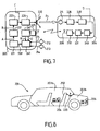
- the figure 8 schematically represents an alternative embodiment of the vehicle 201, seen from the side.
- the speakers 220 are here arranged on the rear shelf wall which separates the interior space 203 into a passenger compartment 203a and a trunk 203b.
- This wall and backs 250 of the rear seats generally form a good screen for the transmission of infrasonic pressure variations.
- the infrasonic pressure variations generated by the speakers 220 in the passenger compartment 203a are in phase opposition with respect to that in the trunk 203b.
- the identification device 206 is located in the trunk 203b, the signal D will be in phase opposition with respect to what it would have been if the device 206 had been in the passenger compartment 203a, and the word M detected by the Circuit 242 will have all its bits reversed.
- the comparator 241 can determine whether the identification device is located in the passenger compartment 203a, in the trunk 203b, or outside the vehicle 201:
- the comparator 241 calculates the Hamming distance between Sb t and M. Si the words M and Sb t are equal, possibly to one or two bits of error is that the device 206 is in the passenger compartment 203a. In other words, if the Hamming distance between Sb t and M is less than a given threshold, the comparator 241 determines that the device 206 is in the passenger compartment 203a. If this is not the case, the comparator calculates the Hamming distance between Sb t and not (M), the logical inverse of the word M.
- the comparator 241 can also determine whether the identification device is located in the passenger compartment 203a, in the trunk 203b, or outside the vehicle 201, on the basis of the internal reference signals P i and P c external and analog content of the signal D.
- the reference sensor interior 212 is arranged in the passenger compartment 203a.
- the signal D is very similar to the internal reference signal P i is that the device 206 is located in the passenger compartment 203a.
- the signal D when inverted in phase, is very similar to the internal reference signal P i , it is that the device 206 is located in the trunk 203b.
- the signal D is closer to the external reference signal P e , the device 206 is outside the vehicle 1.
- the loudspeakers 220 are not arranged on a wall separating the passenger compartment 203a from the trunk 203b, it is possible to use an additional loudspeaker (not shown) arranged in the chest 203b.
- the speakers 220 and the additional loudspeaker are sequentially energized, and the signals are processed in the manner just described.
- Another variant when the structure of the vehicle strongly isolates the passenger compartment of the trunk, to the point that the infrasonic signals do not pass significantly from one to the other, is to excite the speakers 220 and the additional speaker simultaneously but based on two different binary words Sb1 t and Sb2 t .
- This variant has the advantage of speed, the device 206 can be located from the first issue of the words Sb1 t and Sb2 t .
- the invention which has just been described can be completed by a localization using, for example, loop antennas having specific detection zones, making it possible, for example, to locate the identification device outside the vehicle 1 to near a right door, a left door or the trunk.
- the invention can be combined with a protection based on the measurement of a time shift of signals.
- the infrasonic pressure variations emitted by the loudspeakers 220 under the control of the central unit 205 are arbitrary. In other words they do not include components corresponding to a given binary word.
- the location of the device 206 is then based solely on the comparison of the reference signals P i and P e and the analog content of the signal D.
- This embodiment variant can also be apply to the passive embodiment, provided that the vehicle is equipped with a device capable of producing an infrasonic signal, for example a car radio.
- the idea here is to artificially produce an infrasonic excitation in the interior space of the vehicle, under the control of the central unit 5 or 205. For example, this excitation is created when, at the moment when the identification device 6 or 206 must be located, no significant signal is perceived by the sensors 12 and 13 or 212 and 213.
- this variant has the advantage of creating a difference between the interior space 3 or 203 and outside, which increases reliability.
- the driver must normally have access to the vehicle beforehand, so that there should normally be at least one door slam producing an infrasonic excitation that can be exploited by the system.
- Another solution to the problem of the small difference that the infrasonic pressure variations can have in and out of the interior space or the problem of the absence of infrasonic noise in and out of the vehicle is to start the engine of the vehicle when the identification device must be located, which has the effect of creating infrasonic pressure variations. Then, after a short period of time, for example a few seconds, the identification device is located. If it is outside, the engine is shut down. If he is inside, leave the engine on.
- vibratory mode is described with reference to the figure 9 .
- Elements that are the same or similar to passive mode elements are designated by the same reference numerals, increased by 300.
- the vehicle 301 comprises walls 302.
- the wall 302 comprises in particular the floor and the doors of the vehicle 301.
- the wall 302 may be partially open, in other words the vehicle 301 may be a convertible.
- the vehicle 301 includes a hands-free control system.
- This free hand control system includes a central unit 305 adapted to establish an electromagnetic communication 310 with an identification device 306 through antennas 307, 308.
- the identification device 306 comprises an acceleration sensor 311 and a controller 309.
- the acceleration sensor 311 may be an angular acceleration sensor, measuring the angular acceleration along one, two or three axes, and outputting a rotation vector respectively to one, two or three dimensions.
- the rotation vector is for example represented by one, two or three electrical voltages, each respectively corresponding to the component of the rotation vector along one of the measurement axes.
- the rotation vector is represented by a single voltage corresponding to its module.
- the acceleration sensor 311 may also be a linear acceleration sensor, measuring the linear acceleration along one, two or three axes, and outputting an acceleration vector respectively to one, two or three dimensions.
- the acceleration vector is for example represented by one, two or three electrical voltages, each corresponding respectively to the component of the acceleration vector along one of the measurement axes.
- the acceleration vector is represented by a single voltage corresponding to its module.
- the modulus of the rotation vector or the acceleration vector provides a measurement signal S m representative of the acceleration of the identification device 306.
- the controller 309 transmits this measurement signal S m to the central unit 305, in a digitized and encrypted manner, thanks to the antenna 308 and to electromagnetic communication 310.
- the central unit 305 includes a decoder for decrypting the received signal.
- the control system also comprises an acceleration sensor 312, for example of the same type as the acceleration sensor 311.
- the sensor 312 is fixed to the vehicle structure 301 so as to undergo the movements of the vehicle 301.
- the sensor 312 can be a specific sensor for the free hand control system, or be a sensor also for other control functions of the For example, the sensor 312 may also be used to control the engagement of airbag cushions.
- the sensor 312 is connected to the central unit 305.
- the central unit 305 has the measurement signal S m coming from the sensor 311, and a reference signal S r coming from the sensor 312.
- the identification device 306 If the identification device 306 is in the vehicle 301, it will undergo movements corresponding to the movements of the vehicle 301, possibly combined with the movements of a user carrying the device 306 in the vehicle.
- the measurement signal S m and the reference signal S r will both comprise a component corresponding to an acceleration of the vehicle 301, and will therefore be correlated.
- the measurement signal S m and the reference signal S r will be independent of one another and will therefore not be correlated.
- the comparison of the measurement signal S m and the reference signal S r is carried out for example in the following manner.
- the central unit 305 establishes the communication 310 with the identification device 306 for exchanging messages according to a known cryptographic method, in order to authenticate the identification device 306 and / or to send him an interrogation message. Then, the identification device 306 starts transmitting the measurement signal S m to the central unit 305.
- the central unit 305 stores the received signals and calculates a correlation level between the measurement signal S m and the reference signal S r . More precisely, the central unit 305 determines the envelope of the measurement signal S m and of the reference signal S r .
- the signal envelopes S m and S r will both have peaks and areas of reduced amplitude, correlated way.
- the correlation level can be calculated by performing a correlation product between these envelopes.
- the central unit 305 may, for example, calculate the rms value of the difference between the envelopes of the signals S m and S r .
- the central unit 305 determines that the identification device 306 is in the vehicle 301. If not, the central unit 305 determines that the identification device 306 n is not in the vehicle 301.
- the correlation level must be greater than the threshold level for at least one comparison period of a determined duration, greater than a duration threshold, for example 5 seconds.
- the central unit 305 stores the measurement signal S m and the reference signal S r in a memory and compares these signals during several comparison periods. For example, one of the comparison periods starts from the triggering event mentioned above. Thus, if necessary, it is possible to quickly locate the identification device 306 in the vehicle and allow the start as soon as the driver is installed.
- the central unit 305 controls the starting of the engine of the vehicle 301. This start can take place either after a predetermined time, for example 5 seconds, after the triggering event, either following the actuation of a control button provided for this purpose, placed for example on the dashboard of the vehicle 301. A comparison period begins when starting the engine, and ends a few seconds later, for example between 5 and 10 seconds later. If the correlation level between the measurement signal S m and the reference signal S r during this comparison period is greater than the threshold level, the motor is left on. In the opposite case, the central unit 305 commands the stopping of the motor.
- the control system according to the vibratory mode can be combined with the control system according to one of passive, active-1 or active-2 infrasonic modes.
- the identification device 306 comprises an acceleration sensor 311 and an infrasonic sensor 11, 111 or 211 and the vehicle also comprises at least one acceleration sensor and, if necessary, infrasonic sensors. In the case of these combinations, a dual position detection of the identification device is implemented, which further increases the security against piracy.
- the identification device 6 or 206 comprises a combined acceleration and infrasound sensor.
- at least one of the sensors 12, 13 or 212, 213 may also be a combined acceleration and infrasound sensor.
- the measurement signal transmitted by the identification device to the central unit reflects both the pressure variations in the environment of the identification device and the accelerations it undergoes.
- the central unit determines the location of the identification device by comparing this measurement signal with an infrasonic interior reference signal and / or an infrasonic internal reference signal and an accelerometric reference signal.
- the measurement signal of a combined acceleration and infrasonic sensor installed in the vehicle can also be used as a reference signal in this case.
- An infrasonic outdoor sensor is not always necessary.
- the sensor 319 is based on the principle of the electret microphone and comprises a housing 320 made of aluminum, for example of circular cylindrical shape.
- the housing 320 has an opening 322 for passing the pressure variations.
- a metallized membrane 321 is arranged inside the housing 320, and fixed thereto on its periphery.
- the metallized membrane 321 is deformable.
- the figure 10 represents the membrane 321 in its undistorted position.
- the figure 12 represents the membrane 321 in a deformed position, the deformation having been exaggerated for the clarity of the drawing.
- a measuring electrode 323 is constituted by a metal disk fixed in the housing 320 parallel to the metallized membrane 321, in its undeformed position.
- the measuring electrode 323 and the metallized membrane 321 together form a variable capacitor which is connected to a measuring circuit 330, as represented by the arrow 324.
- An example of a measuring circuit 330 is shown on FIG. figure 13 surrounded by broken lines. It comprises a variable capacitor 331 formed by the electrode 323 and the membrane 321.
- the electrode 323 is connected to the gate of a field effect transistor 332 whose two other terminals form the outputs of the sensor, one being connected to ground, the other being connected, via a resistor 333, for example 2 k ⁇ , to a voltage source of for example + 3V.
- the voltage present at the terminal 334 is variable and corresponds to capacitance variations of the capacitor 331.
- the measuring circuit 330 also comprises a resistor 335 of several M ⁇ .
- the metallized membrane 321 deforms and the capacitance of the capacitor formed by the membrane 321 and the electrode 323 varies. This capacitance variation is transformed by the measuring circuit into an output signal, for example in the form of a variable voltage.
- the sensor 319 comprises two masses 325 and 326 attached to the metallized membrane 321, near the center of the membrane 321, diametrically opposite one another.
- the masses 325 and 326 are for example small volumes of dense material such as lead or a tin alloy.
- the centers of gravity of the masses 325 and 326 are located above the membrane 321.
- the mass 325 is also fixed to the housing 320 by a tab 327 extending along an axis Y and connecting the mass 325 to the housing 320, at the level of the membrane.
- the mass 325 can pivot about a pivot axis defined by the attachment of the tab 327 to the housing 320.
- the mass 326 is fixed to the housing 320 by a tab 328 extending along an axis Z, perpendicular to the Y axis.
- the masses 325 and 326 deform the membrane 321 and the capacity of the capacitor formed by the membrane 321 and the electrode 323 varies. This capacitance variation is transformed by the measuring circuit into an output signal.
- the masses 325 and 326 move along this axis X and deform the membrane.
- the mass 325 will undergo, because its center of gravity is offset with respect to the pivot axis defined by the attachment of the tab 327 to the housing 320, a pair of pivoting.
- the mass 325 deforms the membrane 321, as shown in FIG. figure 12 , while the mass 326 is held by the tab 328.
- acceleration or displacement of the sensor 319 in a direction parallel to the plane of the membrane 321 generates a tilting torque of the mass 325 or 326 capable of deforming the membrane detectably.
- the tabs 327 and 328 are not essential for this, but they strengthen the attachment of the masses 325 and 326 and allow to create an important lever arm.
- the senor 319 makes it possible to measure both an acceleration and pressure variations, especially in an infrasonic frequency range.
- the membrane 321 may be sized to deform in response to pressure waves in other frequency domains.
- control systems that have been described include an identification device. They could also include several, each being worn by a different authorized user.
- control systems that have been described include a radio link, i.e. from the central unit to the identification device. We can do without this link.
- the identification device contains a secret private key also known to the central unit. This secret key is also used by the encoder 131 or 231 and the decoder 126 or the circuit 242.
Landscapes
- Engineering & Computer Science (AREA)
- Mechanical Engineering (AREA)
- Computer Networks & Wireless Communication (AREA)
- Physics & Mathematics (AREA)
- General Physics & Mathematics (AREA)
- Lock And Its Accessories (AREA)
- Measuring Fluid Pressure (AREA)
- Control Of Electric Motors In General (AREA)
Claims (16)
- Handfreies Steuerungssystem für ein Fahrzeug (301), mit einer in dem Fahrzeug angeordneten zentralen Steuereinheit (305) und einer von einem Benutzer zu tragenden Identifikationsvorrichtung (306), wobei die Identifikationsvorrichtung einen Sender zur drahtlosen Fernübertragung von Signalen zu der zentralen Steuereinheit aufweist, wobei die zentrale Steuereinheit einen Empfänger zum Empfang dieser Signale umfasst, wobei die zentrale Steuereinheit Lokalisierungsmittel umfasst, um an Hand dieser Signale festzustellen, ob sich die Identifikationsvorrichtung innerhalb oder außerhalb des Fahrzeugs befindet, wobei die Zentraleinheit Steuerungsmittel umfasst, um in Abhängigkeit von der Lokalisierung der Identifikationsvorrichtung innerhalb oder außerhalb des Fahrzeugs das Anlassen des Fahrzeugs zu autorisieren oder zu verhindern und/oder um Verriegelungs-/Entriegelungsmittel der Schlösser der Türen des Fahrzeugs zu steuern, wobei die Identifikationsvorrichtung einen ersten Sensor (311) zur Messung einer Beschleunigung der Identifikationsvorrichtung umfasst, wobei der Sender der Identifikationsvorrichtung ein von der durch den ersten Sensor gemessenen Beschleunigung abhängiges Messsignal an die Zentraleinheit übertragen kann, wobei die Lokalisierungsmittel der Zentraleinheit einen Komparator umfassen, der das Antwortsignal mit einem Referenzsignal vergleichen kann, um die Lokalisierung der Identifikationsvorrichtung innerhalb oder außerhalb des Fahrzeugs durchzuführen, wobei das Steuerungssystem einen zweiten Sensor (312) umfasst, der so in dem Fahrzeug angeordnet ist, dass er eine Beschleunigung des Fahrzeugs messen kann, wobei der zweite Sensor mit der Zentraleinheit verbunden ist, dadurch gekennzeichnet, dass das Referenzsignal von der durch den zweiten Sensor gemessenen Beschleunigung abhängt.
- System gemäß Anspruch 1, dadurch gekennzeichnet, dass der erste Sensor eine Winkelbeschleunigung messen kann, wobei das Messsignal vom Betrag des von dem ersten Sensor gelieferten Rotationsvektors abhängt, wobei der zweite Sensor eine Winkelbeschleunigung messen kann, wobei das Referenzsignal von dem Betrag eines von dem zweiten Sensor gelieferten Rotationsvektors abhängt.
- System gemäß Anspruch 1 oder Anspruch 2, dadurch gekennzeichnet, dass der erste Sensor eine Linearbeschleunigung in wenigstens einer Richtung messen kann, wobei das Messsignal vom Betrag eines von dem ersten Sensor gelieferten Bescheunigungsvektors abhängt, wobei der zweite Sensor eine Linearbeschleunigung in wenigstens einer Richtung messen kann, wobei das Referenzsignal von dem Betrag eines von dem zweiten Sensor gelieferten Beschleunigungsvektors abhängt.
- System gemäß einem der Ansprüche 1 bis 3, dadurch gekennzeichnet, dass der Komparator einen Speicher umfasst, wobei der Komparator das Messsignal und das Referenzsignal in dem Speicher während wenigstens eines Vergleichszeitraums speichern kann.
- System gemäß Anspruch 4, dadurch gekennzeichnet, dass die Zentraleinheit mit einem Sensor so verbindbar ist, dass sie von dem Sensor ein Auslösesignal empfangen kann, wobei der Komparator das Messsignal und das Referenzsignal während eines Vergleichszeitraums speichern kann, der im Wesentlichen mit dem Empfang des Auslösesignals beginnt.
- System gemäß Anspruch 5, dadurch gekennzeichnet, dass der das Auslösesignal erzeugende Sensor ein Türgriffsensor ist, der auf die Betätigung eines Griffs der Tür reagiert.
- System gemäß Anspruch 5, dadurch gekennzeichnet, dass der das Auslösesignal erzeugende Sensor ein Betätigungsknopf ist, der zur Steuerung des Anlassens des Fahrzeugs dient.
- System gemäß einem der Ansprüche 4 bis 7, dadurch gekennzeichnet, dass es einen Betätigungsknopf umfasst, der zur Steuerung des Anlassens des Fahrzeugs dient, wobei der Komparator das Messsignal und das Referenzsignal während eines Vergleichszeitraums speichern kann, der nach der Betätigung des Betätigungsknopfes endet.
- System gemäß einem der Ansprüche 4 bis 8, dadurch gekennzeichnet, dass die Zentraleinheit das Anlassen des Motors des Fahrzeugs detektieren kann, wobei der Komparator das Messsignal und das Referenzsignal während eines Vergleichszeitraums speichern kann, der nach dem Anlassen endet.
- System gemäß einem der Ansprüche 1 bis 9, dadurch gekennzeichnet, dass der Komparator einen Korrelationsgrad zwischen einer zeitlichen Einhüllenden des Messsignals und einer zeitlichen Einhüllenden des Referenzsignals bestimmen kann, wobei die Lokalisierungsmittel die Lokalisierung der Identifikationsvorrichtung innerhalb oder außerhalb des Fahrzeugs in Abhängigkeit von dem Korrelationsgrad durchführen können.
- System gemäß einem der vorhergehenden Ansprüche, dadurch gekennzeichnet, dass die Identifikationsvorrichtung einen Drucksensor (11, 111, 211) umfasst, der Druckänderungen in der Umgebung der Identifikationsvorrichtung in einem Infraschallfrequenzbereich messen kann, wobei der Sender der Identifikationsvorrichtung ein von den durch den Sensor gemessenen Druckänderungen abhängiges Antwortsignal an die Zentraleinheit übertragen kann, wobei der Komparator das Antwortsignal mit einem Druckreferenzsignal vergleichen kann, mit welchem Druckänderungen in dem Innenraum in einem Infraschallfrequenzbereich korreliert sind, um die Lokalisierung der Identifikationsvorrichtung innerhalb oder außerhalb des Innenraums durchzuführen.
- System gemäß Anspruch 11, dadurch gekennzeichnet, dass es einen kombinierten Druck- und Beschleunigungssensor (319) umfasst, welcher den ersten Sensor und den Drucksensor bildet und dessen kombiniertes Messsignal das Messsignal und das Antwortsignal bildet, wobei der zweite Sensor ein zweiter kombinierter Druck- und Beschleunigungssensor (319) ist, der Druckänderungen in dem Innenraum des Fahrzeugs in einem Infraschallfrequenzbereich messen kann, wobei das Referenzsignal und das Druckreferenzsignal von einem einzigen Referenzsignal gebildet werden, das durch den zweiten kombinierten Druck- und Beschleunigungssensor gemessen wird.
- System gemäß Anspruch 12, dadurch gekennzeichnet, dass der kombinierte Beschleunigungs- und Druckwellensensor (319) einen variablen Kondensator umfasst, der von einer Messelektrode (323) und einer leitfähigen, durch Druckänderungen verformbaren Membran (321) gebildet wird, wobei der variable Kondensator mit einer Messschaltung (330) verbunden ist, die ein Messsignal erzeugen kann, das Kapazitätsänderungen des variablen Kondensators entspricht, wobei der kombinierte Sensor wenigstens eine Masse (325, 326) umfasst, die so an der leitfähigen Membran befestigt ist, dass sie die leitfähige Membran als Reaktion auf eine Beschleunigung des kombinierten Sensors verformt.
- System gemäß Anspruch 13, dadurch gekennzeichnet, dass der Schwerpunkt der wenigstens einen Masse von der Membran beabstandet ist.
- System gemäß Anspruch 14, dadurch gekennzeichnet, dass es ein Gehäuse (320) umfasst, wobei die leitfähige Membran an dem Gehäuse befestigt ist, wobei die wenigstens eine Masse mittels eines starren Arms so mit dem Gehäuse verbunden ist, dass sie um eine Drehachse schwenkbar ist.
- Verfahren zur Steuerung eines handfreien Steuerungssystems für ein Fahrzeug (301), wobei das System eine in dem Fahrzeug angeordnete zentrale Steuereinheit (305) und eine von einem Benutzer zu tragende Identifikationsvorrichtung (306) umfasst, wobei das Verfahren die Schritte umfasst, bestehend aus:Messen einer Beschleunigung der Identifikationsvorrichtung mittels eines ersten Sensors (311),drahtloses Fernübertragen von Signalen von der Identifikationsvorrichtung zu der zentralen Steuereinheit, wobei die Signale ein Messsignal umfassen, das von der Beschleunigung der Identifikationsvorrichtung abhängt,Lokalisieren der Identifikationsvorrichtung innerhalb oder außerhalb des Fahrzeugs in Abhängigkeit von dem Vergleich des Messsignals mit einem Referenzsignal, das der Zentraleinheit zur Verfügung gestellt wird,Autorisieren oder Verhindern des Anlassens des Fahrzeugs und/oder Steuern der Verriegelungs-/Entriegelungsmittel der Schlösser der Türen des Fahrzeugs in Abhängigkeit von der Lokalisierung der Identifikationsvorrichtung innerhalb oder außerhalb des Fahrzeugs,wobei das Verfahren den Schritt umfasst, bestehend aus der Messung einer Beschleunigung des Fahrzeugs mit einem in dem Fahrzeug angeordneten zweiten Sensor (312),
dadurch gekennzeichnet, dass das Referenzsignal von der durch den zweiten Sensor gemessenen Beschleunigung des Fahrzeugs abhängt.
Priority Applications (3)
| Application Number | Priority Date | Filing Date | Title |
|---|---|---|---|
| AT05291009T ATE388865T1 (de) | 2005-05-11 | 2005-05-11 | Fernbedienungssystem für kraftfahrzeug mit beschleunigungssensor und/oder drucksensor |
| DE602005005305T DE602005005305T2 (de) | 2005-05-11 | 2005-05-11 | Fernbedienungssystem für Kraftfahrzeug mit Beschleunigungssensor und/oder Drucksensor |
| EP05291009A EP1721792B1 (de) | 2005-05-11 | 2005-05-11 | Fernbedienungssystem für Kraftfahrzeug mit Beschleunigungssensor und/oder Drucksensor |
Applications Claiming Priority (1)
| Application Number | Priority Date | Filing Date | Title |
|---|---|---|---|
| EP05291009A EP1721792B1 (de) | 2005-05-11 | 2005-05-11 | Fernbedienungssystem für Kraftfahrzeug mit Beschleunigungssensor und/oder Drucksensor |
Publications (2)
| Publication Number | Publication Date |
|---|---|
| EP1721792A1 EP1721792A1 (de) | 2006-11-15 |
| EP1721792B1 true EP1721792B1 (de) | 2008-03-12 |
Family
ID=35692862
Family Applications (1)
| Application Number | Title | Priority Date | Filing Date |
|---|---|---|---|
| EP05291009A Expired - Lifetime EP1721792B1 (de) | 2005-05-11 | 2005-05-11 | Fernbedienungssystem für Kraftfahrzeug mit Beschleunigungssensor und/oder Drucksensor |
Country Status (3)
| Country | Link |
|---|---|
| EP (1) | EP1721792B1 (de) |
| AT (1) | ATE388865T1 (de) |
| DE (1) | DE602005005305T2 (de) |
Families Citing this family (8)
| Publication number | Priority date | Publication date | Assignee | Title |
|---|---|---|---|---|
| FR2986202A1 (fr) * | 2012-01-26 | 2013-08-02 | Johnson Contr Automotive Elect | Moyen d'authentification portable et systeme de securite de vehicule pour un vehicule automobile |
| DE102015106621A1 (de) * | 2015-04-29 | 2016-11-03 | Hella Kgaa Hueck & Co. | Zugangs-und Fahrberechtigungssystem mit erhöhter Sicherheit gegen Relaisangriffe durch Nutzung von im Berechtigungsmittel integrierter Bewegungssensorik |
| DE102015107643A1 (de) * | 2015-05-15 | 2016-11-17 | Hella Kgaa Hueck & Co. | Zugangs-und Fahrberechtigungssystem mit erhöhter Sicherheit gegen Relaisangriffe auf die Transpondingschnittstelle Teil - III |
| DE102015109468A1 (de) * | 2015-06-15 | 2016-12-15 | Hella Kgaa Hueck & Co. | Zugangs-und Fahrberechtigungssystem mit erhöhter Sicherheit gegen Relaisangriffe durch Verifikation der Ortbestimmung |
| FR3041491B1 (fr) * | 2015-09-18 | 2017-11-03 | Valeo Comfort & Driving Assistance | Procede d'aide a la determination d'un positionnement d'un identifiant par rapport a un vehicule |
| DE102016111706A1 (de) * | 2016-06-27 | 2017-12-28 | Hella Kgaa Hueck & Co. | Verfahren und System zum Erfassen einer Relativposition eines mobilen Endgeräts in Bezug auf ein Fahrzeug |
| DE102018002969A1 (de) * | 2018-04-12 | 2018-11-22 | Daimler Ag | Verfahren zum Verifizieren einer Fahrberechtigung |
| DE102018004997A1 (de) * | 2018-06-22 | 2019-12-24 | Giesecke+Devrient Mobile Security Gmbh | Diebstahlschutz eines Automobils mittels Kontextmodellierung eines berechtigten Benutzers |
Family Cites Families (2)
| Publication number | Priority date | Publication date | Assignee | Title |
|---|---|---|---|---|
| DE19850176C1 (de) * | 1998-10-30 | 2000-08-31 | Siemens Ag | Diebstahlschutzeinrichtung für ein Kraftfahrzeug und Verfahren zum Betreiben der Diebstahlschutzeinrichtung |
| DE10052451C2 (de) * | 2000-10-23 | 2003-06-26 | Siemens Ag | Diebstahlschutzvorrichtung für ein Kraftfahrzeug und Verfahren zum Betreiben der Diebstahlschutzvorrichtung |
-
2005
- 2005-05-11 AT AT05291009T patent/ATE388865T1/de not_active IP Right Cessation
- 2005-05-11 EP EP05291009A patent/EP1721792B1/de not_active Expired - Lifetime
- 2005-05-11 DE DE602005005305T patent/DE602005005305T2/de not_active Expired - Lifetime
Also Published As
| Publication number | Publication date |
|---|---|
| DE602005005305D1 (de) | 2008-04-24 |
| DE602005005305T2 (de) | 2009-03-26 |
| ATE388865T1 (de) | 2008-03-15 |
| EP1721792A1 (de) | 2006-11-15 |
Similar Documents
| Publication | Publication Date | Title |
|---|---|---|
| EP2350984B1 (de) | Einrichtung zum automatischen entriegeln eines öffnungsfähigen panels eines kraftfahrzeugs | |
| EP0596805B1 (de) | Fernbetätigungssystem zum Sperren und Entsperren von Türen und Öffnungsteilen eines Kraftfahrzeugs | |
| US10665090B2 (en) | Trainable transceiver and mobile communications device systems and methods | |
| CN110382311B (zh) | 用于控制车辆的锁定元件的方法 | |
| EP0926305B1 (de) | Sicherheitsvorrichtung, insbesondere für Kraftfahrzeuge | |
| FR2986202A1 (fr) | Moyen d'authentification portable et systeme de securite de vehicule pour un vehicule automobile | |
| FR2858347A1 (fr) | Procede permettant de confirmer une autorisation de verrouiller et de deverrouiller et/ou d'utiliser un objet et dispositif de securite | |
| EP2350983A1 (de) | Einrichtung zum automatischen entriegeln eines öffnungsfähigen panels eines kraftfahrzeugs | |
| EP1721793B1 (de) | Freihändiges Kontrollsystem für Fahrzeuge | |
| FR2917771A1 (fr) | Procede securise de fermeture automatique d'un hayon de vehicule automobile | |
| EP2183453A1 (de) | Verfahren zur automatischen entriegelung einers öffnungselements einer kraftfahrzeugs für ein freispechsystem und vorrichtung zur umsetzung des verfahrens | |
| EP3266003A1 (de) | Verfahren zur steuerung des zugriffs auf mindestens eine funktion eines kraftfahrzeugs | |
| FR2813630A1 (fr) | Procede pour verrouiller automatiquement un ouvrant de vehicule a l'aide d'un systeme d'acces mains libres et d'un capteur d'approche | |
| FR3119465A1 (fr) | Procede d’activation d’une fonction d’un vehicule automobile et dispositif d’activation associe | |
| FR2971386A1 (fr) | Systeme de determination de presence d'un identificateur a l'interieur d'un habitacle | |
| EP1721792A1 (de) | Fernbedienungssystem für Kraftfahrzeug mit Beschleunigungssensor und/oder Drucksensor | |
| EP1362753B1 (de) | Steuerung eines systems für den zugang und/oder den start eines kraftfahrzeugs in einer frequenzgestörten zone | |
| EP1499522B1 (de) | System zur steuerung des zugangs zu einem und/oder des starts eines kraftfahrzeugs mit benutzerwarnungsmittel | |
| FR2880719A1 (fr) | Systeme de detection et procede permettant de determiner un etat d'alarme dans celui-ci | |
| WO2013087197A1 (fr) | Procédé de caractérisation d'un dispositif portable par une antenne embarquée dans un véhicule automobile | |
| EP1941475A1 (de) | Verfahren zur verarbeitung von durch einen beschleunigungsmesser durchgeführten beschleunigungsmassnahmen, beschleunigungssensor und mit derartigen sensoren ausgestattetes alarmsystem | |
| FR2765610A1 (fr) | Vehicule automobile avec un systeme de fermeture a ouvrir ou a verrouiller au moyen d'une telecommande | |
| EP2850598A1 (de) | Fernsteuerung zur aktivierung der funktionen eines kraftfahrzeugs unter verwendung von durch die fernsteuerung ausgegebenen signalen, fernsteuerungssystem mit einer zentralen einheit und einer fernbedienung sowie verfahren zur aktivierung der funktionen eines kraftfahrzeugs mit einem fernsteuerungssystem | |
| EP0901021A1 (de) | Verfahren und Vorrichtung zur Erfassung des Eindringens in ein Fahrzeug durch Ultraschallwellenübertragung und -empfang | |
| WO2023166014A1 (fr) | Procédé de détection et discrimination de gestes |
Legal Events
| Date | Code | Title | Description |
|---|---|---|---|
| PUAI | Public reference made under article 153(3) epc to a published international application that has entered the european phase |
Free format text: ORIGINAL CODE: 0009012 |
|
| 17P | Request for examination filed |
Effective date: 20060617 |
|
| AK | Designated contracting states |
Kind code of ref document: A1 Designated state(s): AT BE BG CH CY CZ DE DK EE ES FI FR GB GR HU IE IS IT LI LT LU MC NL PL PT RO SE SI SK TR |
|
| AX | Request for extension of the european patent |
Extension state: AL BA HR LV MK YU |
|
| 17Q | First examination report despatched |
Effective date: 20070425 |
|
| AKX | Designation fees paid |
Designated state(s): AT BE BG CH CY CZ DE DK EE ES FI FR GB GR HU IE IS IT LI LT LU MC NL PL PT RO SE SI SK TR |
|
| GRAP | Despatch of communication of intention to grant a patent |
Free format text: ORIGINAL CODE: EPIDOSNIGR1 |
|
| GRAS | Grant fee paid |
Free format text: ORIGINAL CODE: EPIDOSNIGR3 |
|
| GRAA | (expected) grant |
Free format text: ORIGINAL CODE: 0009210 |
|
| AK | Designated contracting states |
Kind code of ref document: B1 Designated state(s): AT BE BG CH CY CZ DE DK EE ES FI FR GB GR HU IE IS IT LI LT LU MC NL PL PT RO SE SI SK TR |
|
| REG | Reference to a national code |
Ref country code: GB Ref legal event code: FG4D Free format text: NOT ENGLISH |
|
| REG | Reference to a national code |
Ref country code: CH Ref legal event code: EP |
|
| REG | Reference to a national code |
Ref country code: IE Ref legal event code: FG4D Free format text: LANGUAGE OF EP DOCUMENT: FRENCH |
|
| REF | Corresponds to: |
Ref document number: 602005005305 Country of ref document: DE Date of ref document: 20080424 Kind code of ref document: P |
|
| PG25 | Lapsed in a contracting state [announced via postgrant information from national office to epo] |
Ref country code: FI Free format text: LAPSE BECAUSE OF FAILURE TO SUBMIT A TRANSLATION OF THE DESCRIPTION OR TO PAY THE FEE WITHIN THE PRESCRIBED TIME-LIMIT Effective date: 20080312 Ref country code: LT Free format text: LAPSE BECAUSE OF FAILURE TO SUBMIT A TRANSLATION OF THE DESCRIPTION OR TO PAY THE FEE WITHIN THE PRESCRIBED TIME-LIMIT Effective date: 20080312 |
|
| PG25 | Lapsed in a contracting state [announced via postgrant information from national office to epo] |
Ref country code: AT Free format text: LAPSE BECAUSE OF FAILURE TO SUBMIT A TRANSLATION OF THE DESCRIPTION OR TO PAY THE FEE WITHIN THE PRESCRIBED TIME-LIMIT Effective date: 20080312 |
|
| NLV1 | Nl: lapsed or annulled due to failure to fulfill the requirements of art. 29p and 29m of the patents act | ||
| PG25 | Lapsed in a contracting state [announced via postgrant information from national office to epo] |
Ref country code: SI Free format text: LAPSE BECAUSE OF FAILURE TO SUBMIT A TRANSLATION OF THE DESCRIPTION OR TO PAY THE FEE WITHIN THE PRESCRIBED TIME-LIMIT Effective date: 20080312 Ref country code: PL Free format text: LAPSE BECAUSE OF FAILURE TO SUBMIT A TRANSLATION OF THE DESCRIPTION OR TO PAY THE FEE WITHIN THE PRESCRIBED TIME-LIMIT Effective date: 20080312 |
|
| REG | Reference to a national code |
Ref country code: IE Ref legal event code: FD4D |
|
| PG25 | Lapsed in a contracting state [announced via postgrant information from national office to epo] |
Ref country code: ES Free format text: LAPSE BECAUSE OF FAILURE TO SUBMIT A TRANSLATION OF THE DESCRIPTION OR TO PAY THE FEE WITHIN THE PRESCRIBED TIME-LIMIT Effective date: 20080623 Ref country code: PT Free format text: LAPSE BECAUSE OF FAILURE TO SUBMIT A TRANSLATION OF THE DESCRIPTION OR TO PAY THE FEE WITHIN THE PRESCRIBED TIME-LIMIT Effective date: 20080814 Ref country code: SE Free format text: LAPSE BECAUSE OF FAILURE TO SUBMIT A TRANSLATION OF THE DESCRIPTION OR TO PAY THE FEE WITHIN THE PRESCRIBED TIME-LIMIT Effective date: 20080612 Ref country code: SK Free format text: LAPSE BECAUSE OF FAILURE TO SUBMIT A TRANSLATION OF THE DESCRIPTION OR TO PAY THE FEE WITHIN THE PRESCRIBED TIME-LIMIT Effective date: 20080312 Ref country code: CZ Free format text: LAPSE BECAUSE OF FAILURE TO SUBMIT A TRANSLATION OF THE DESCRIPTION OR TO PAY THE FEE WITHIN THE PRESCRIBED TIME-LIMIT Effective date: 20080312 |
|
| PG25 | Lapsed in a contracting state [announced via postgrant information from national office to epo] |
Ref country code: RO Free format text: LAPSE BECAUSE OF FAILURE TO SUBMIT A TRANSLATION OF THE DESCRIPTION OR TO PAY THE FEE WITHIN THE PRESCRIBED TIME-LIMIT Effective date: 20080312 Ref country code: NL Free format text: LAPSE BECAUSE OF FAILURE TO SUBMIT A TRANSLATION OF THE DESCRIPTION OR TO PAY THE FEE WITHIN THE PRESCRIBED TIME-LIMIT Effective date: 20080312 |
|
| BERE | Be: lapsed |
Owner name: DELPHI TECHNOLOGIES, INC. Effective date: 20080531 |
|
| PG25 | Lapsed in a contracting state [announced via postgrant information from national office to epo] |
Ref country code: IS Free format text: LAPSE BECAUSE OF FAILURE TO SUBMIT A TRANSLATION OF THE DESCRIPTION OR TO PAY THE FEE WITHIN THE PRESCRIBED TIME-LIMIT Effective date: 20080712 Ref country code: MC Free format text: LAPSE BECAUSE OF NON-PAYMENT OF DUE FEES Effective date: 20080531 |
|
| PLBE | No opposition filed within time limit |
Free format text: ORIGINAL CODE: 0009261 |
|
| STAA | Information on the status of an ep patent application or granted ep patent |
Free format text: STATUS: NO OPPOSITION FILED WITHIN TIME LIMIT |
|
| PG25 | Lapsed in a contracting state [announced via postgrant information from national office to epo] |
Ref country code: EE Free format text: LAPSE BECAUSE OF FAILURE TO SUBMIT A TRANSLATION OF THE DESCRIPTION OR TO PAY THE FEE WITHIN THE PRESCRIBED TIME-LIMIT Effective date: 20080312 Ref country code: IE Free format text: LAPSE BECAUSE OF FAILURE TO SUBMIT A TRANSLATION OF THE DESCRIPTION OR TO PAY THE FEE WITHIN THE PRESCRIBED TIME-LIMIT Effective date: 20080312 Ref country code: DK Free format text: LAPSE BECAUSE OF FAILURE TO SUBMIT A TRANSLATION OF THE DESCRIPTION OR TO PAY THE FEE WITHIN THE PRESCRIBED TIME-LIMIT Effective date: 20080312 |
|
| 26N | No opposition filed |
Effective date: 20081215 |
|
| PG25 | Lapsed in a contracting state [announced via postgrant information from national office to epo] |
Ref country code: BE Free format text: LAPSE BECAUSE OF NON-PAYMENT OF DUE FEES Effective date: 20080531 |
|
| PG25 | Lapsed in a contracting state [announced via postgrant information from national office to epo] |
Ref country code: BG Free format text: LAPSE BECAUSE OF FAILURE TO SUBMIT A TRANSLATION OF THE DESCRIPTION OR TO PAY THE FEE WITHIN THE PRESCRIBED TIME-LIMIT Effective date: 20080612 |
|
| PG25 | Lapsed in a contracting state [announced via postgrant information from national office to epo] |
Ref country code: CY Free format text: LAPSE BECAUSE OF FAILURE TO SUBMIT A TRANSLATION OF THE DESCRIPTION OR TO PAY THE FEE WITHIN THE PRESCRIBED TIME-LIMIT Effective date: 20080312 |
|
| REG | Reference to a national code |
Ref country code: CH Ref legal event code: PL |
|
| GBPC | Gb: european patent ceased through non-payment of renewal fee |
Effective date: 20090511 |
|
| PG25 | Lapsed in a contracting state [announced via postgrant information from national office to epo] |
Ref country code: LI Free format text: LAPSE BECAUSE OF NON-PAYMENT OF DUE FEES Effective date: 20090531 Ref country code: CH Free format text: LAPSE BECAUSE OF NON-PAYMENT OF DUE FEES Effective date: 20090531 |
|
| PG25 | Lapsed in a contracting state [announced via postgrant information from national office to epo] |
Ref country code: GB Free format text: LAPSE BECAUSE OF NON-PAYMENT OF DUE FEES Effective date: 20090511 |
|
| PG25 | Lapsed in a contracting state [announced via postgrant information from national office to epo] |
Ref country code: LU Free format text: LAPSE BECAUSE OF NON-PAYMENT OF DUE FEES Effective date: 20080511 Ref country code: HU Free format text: LAPSE BECAUSE OF FAILURE TO SUBMIT A TRANSLATION OF THE DESCRIPTION OR TO PAY THE FEE WITHIN THE PRESCRIBED TIME-LIMIT Effective date: 20080913 |
|
| PG25 | Lapsed in a contracting state [announced via postgrant information from national office to epo] |
Ref country code: TR Free format text: LAPSE BECAUSE OF FAILURE TO SUBMIT A TRANSLATION OF THE DESCRIPTION OR TO PAY THE FEE WITHIN THE PRESCRIBED TIME-LIMIT Effective date: 20080312 |
|
| PG25 | Lapsed in a contracting state [announced via postgrant information from national office to epo] |
Ref country code: GR Free format text: LAPSE BECAUSE OF FAILURE TO SUBMIT A TRANSLATION OF THE DESCRIPTION OR TO PAY THE FEE WITHIN THE PRESCRIBED TIME-LIMIT Effective date: 20080613 |
|
| REG | Reference to a national code |
Ref country code: FR Ref legal event code: PLFP Year of fee payment: 12 |
|
| REG | Reference to a national code |
Ref country code: FR Ref legal event code: PLFP Year of fee payment: 13 |
|
| REG | Reference to a national code |
Ref country code: FR Ref legal event code: PLFP Year of fee payment: 14 |
|
| REG | Reference to a national code |
Ref country code: DE Ref legal event code: R082 Ref document number: 602005005305 Country of ref document: DE Representative=s name: REITSTOETTER KINZEBACH, DE Ref country code: DE Ref legal event code: R081 Ref document number: 602005005305 Country of ref document: DE Owner name: APTIV TECHNOLOGIES LIMITED, BB Free format text: FORMER OWNER: DELPHI TECHNOLOGIES, INC., TROY, MICH., US |
|
| PGFP | Annual fee paid to national office [announced via postgrant information from national office to epo] |
Ref country code: IT Payment date: 20190523 Year of fee payment: 15 |
|
| PGFP | Annual fee paid to national office [announced via postgrant information from national office to epo] |
Ref country code: FR Payment date: 20190527 Year of fee payment: 15 |
|
| PG25 | Lapsed in a contracting state [announced via postgrant information from national office to epo] |
Ref country code: FR Free format text: LAPSE BECAUSE OF NON-PAYMENT OF DUE FEES Effective date: 20200531 |
|
| PG25 | Lapsed in a contracting state [announced via postgrant information from national office to epo] |
Ref country code: IT Free format text: LAPSE BECAUSE OF NON-PAYMENT OF DUE FEES Effective date: 20200511 |
|
| P01 | Opt-out of the competence of the unified patent court (upc) registered |
Effective date: 20230425 |
|
| PGFP | Annual fee paid to national office [announced via postgrant information from national office to epo] |
Ref country code: DE Payment date: 20240516 Year of fee payment: 20 |
|
| REG | Reference to a national code |
Ref country code: DE Ref legal event code: R081 Ref document number: 602005005305 Country of ref document: DE Owner name: APTIV TECHNOLOGIES AG, CH Free format text: FORMER OWNER: APTIV TECHNOLOGIES LIMITED, ST. MICHAEL, BB |
|
| REG | Reference to a national code |
Ref country code: DE Ref legal event code: R071 Ref document number: 602005005305 Country of ref document: DE |