EP1722065A1 - Platte mit Hohlprofilträgern zum aussteifen - Google Patents
Platte mit Hohlprofilträgern zum aussteifen Download PDFInfo
- Publication number
- EP1722065A1 EP1722065A1 EP05290991A EP05290991A EP1722065A1 EP 1722065 A1 EP1722065 A1 EP 1722065A1 EP 05290991 A EP05290991 A EP 05290991A EP 05290991 A EP05290991 A EP 05290991A EP 1722065 A1 EP1722065 A1 EP 1722065A1
- Authority
- EP
- European Patent Office
- Prior art keywords
- longitudinal
- panel
- hollow
- leaf
- portions
- Prior art date
- Legal status (The legal status is an assumption and is not a legal conclusion. Google has not performed a legal analysis and makes no representation as to the accuracy of the status listed.)
- Withdrawn
Links
- 230000002787 reinforcement Effects 0.000 title claims description 6
- 230000000295 complement effect Effects 0.000 claims abstract description 4
- 238000000034 method Methods 0.000 claims abstract description 3
- 230000003014 reinforcing effect Effects 0.000 claims description 16
- 238000010276 construction Methods 0.000 claims description 12
- 239000002184 metal Substances 0.000 claims description 12
- 238000004026 adhesive bonding Methods 0.000 claims description 10
- 238000004519 manufacturing process Methods 0.000 claims description 8
- 238000007493 shaping process Methods 0.000 claims description 2
- 238000012550 audit Methods 0.000 claims 1
- 238000009434 installation Methods 0.000 description 5
- 238000007789 sealing Methods 0.000 description 5
- 239000003292 glue Substances 0.000 description 3
- 238000004140 cleaning Methods 0.000 description 2
- 239000000428 dust Substances 0.000 description 2
- 239000011796 hollow space material Substances 0.000 description 2
- 229910000831 Steel Inorganic materials 0.000 description 1
- 238000005452 bending Methods 0.000 description 1
- 230000000903 blocking effect Effects 0.000 description 1
- 230000006835 compression Effects 0.000 description 1
- 238000007906 compression Methods 0.000 description 1
- 238000005520 cutting process Methods 0.000 description 1
- 239000010959 steel Substances 0.000 description 1
- XLYOFNOQVPJJNP-UHFFFAOYSA-N water Substances O XLYOFNOQVPJJNP-UHFFFAOYSA-N 0.000 description 1
Images




Classifications
-
- E—FIXED CONSTRUCTIONS
- E06—DOORS, WINDOWS, SHUTTERS, OR ROLLER BLINDS IN GENERAL; LADDERS
- E06B—FIXED OR MOVABLE CLOSURES FOR OPENINGS IN BUILDINGS, VEHICLES, FENCES OR LIKE ENCLOSURES IN GENERAL, e.g. DOORS, WINDOWS, BLINDS, GATES
- E06B3/00—Window sashes, door leaves, or like elements for closing wall or like openings; Layout of fixed or moving closures, e.g. windows in wall or like openings; Features of rigidly-mounted outer frames relating to the mounting of wing frames
- E06B3/32—Arrangements of wings characterised by the manner of movement; Arrangements of movable wings in openings; Features of wings or frames relating solely to the manner of movement of the wing
- E06B3/48—Wings connected at their edges, e.g. foldable wings
- E06B3/485—Sectional doors
-
- E—FIXED CONSTRUCTIONS
- E06—DOORS, WINDOWS, SHUTTERS, OR ROLLER BLINDS IN GENERAL; LADDERS
- E06B—FIXED OR MOVABLE CLOSURES FOR OPENINGS IN BUILDINGS, VEHICLES, FENCES OR LIKE ENCLOSURES IN GENERAL, e.g. DOORS, WINDOWS, BLINDS, GATES
- E06B3/00—Window sashes, door leaves, or like elements for closing wall or like openings; Layout of fixed or moving closures, e.g. windows in wall or like openings; Features of rigidly-mounted outer frames relating to the mounting of wing frames
- E06B3/70—Door leaves
- E06B2003/7049—Specific panel characteristics
- E06B2003/7053—Specific panel characteristics corrugated
-
- E—FIXED CONSTRUCTIONS
- E06—DOORS, WINDOWS, SHUTTERS, OR ROLLER BLINDS IN GENERAL; LADDERS
- E06B—FIXED OR MOVABLE CLOSURES FOR OPENINGS IN BUILDINGS, VEHICLES, FENCES OR LIKE ENCLOSURES IN GENERAL, e.g. DOORS, WINDOWS, BLINDS, GATES
- E06B3/00—Window sashes, door leaves, or like elements for closing wall or like openings; Layout of fixed or moving closures, e.g. windows in wall or like openings; Features of rigidly-mounted outer frames relating to the mounting of wing frames
- E06B3/70—Door leaves
- E06B3/72—Door leaves consisting of frame and panels, e.g. of raised panel type
- E06B3/723—Door leaves consisting of frame and panels, e.g. of raised panel type at least one side of the frame consisting solely of a bent panel edge
Definitions
- the invention relates to a panel specifically designed for the realization with other similar panels of a garage door leaf, such a leaf and such a garage door, and finally a method of manufacturing such a panel.
- panels for a garage door leaf are made from a single steel plate.
- the document DE-A-42 27 311 relates to a panel of this type formed of a single wall comprising a main portion ribbed in the longitudinal direction and on the longitudinal edges extending parallel to the ribs, two portions shaped by hollow hollow beam-shaped folding. Two such adjacent hollow box-shaped portions belonging to two adjacent panels are spaced from each other by a recessed space visible towards the outside (front) of the leaf. On the right side of this space, and on the inside (rear) side, is the articulation hinge of the two panels.
- a sealing block carried by the lower hollow box-shaped portion of the upper panel, the latter comprising a vertical blocking rib directed downwards and to the rear of which is the sealing block having a profiled form of pseudo-triangle curvilinear.
- a curved rib carried by the hollow box-shaped upper part of the lower panel, the curved rib being generally directed upwards.
- Such an embodiment has the disadvantages, in particular, that there is a hollow space between the two adjacent hollow box-shaped portions of two neighboring panels, clearly visible from the outside of the leaf.
- This hollow space is particularly unsightly, while the aesthetics of garage doors is a requirement increasingly sought by customers.
- This recessed space whose transverse cross-sectional profile is substantially C or U coated, does not allow a convenient evacuation of water in case of rain or cleaning, in addition to dust and debris accumulates there.
- the seal can not be perfectly satisfied, being obtained by sliding contact of the curved rib on the rear face. curved sealing block. Finally, the function anti-finger pliers is not assured.
- the object of the invention is to solve these problems.
- the invention relates to a panel for producing a leaf of a sectional garage door, said panel consisting of a metal wall defining a broad central longitudinal band, generally flat , forming the main part of the panel and extending along its entire length L between two lateral edges and, on either side of the central strip, first and second upper and lower longitudinal portions respectively in the form of a hollow beam obtained by folding or profiling the two longitudinal end portions of the metal wall on itself, each having a generally pseudo-trapezoidal profiled shape with a wing fixed by bonding to the strip towards the inside of the panel.
- the upper longitudinal portion in the form of a hollow beam has a small base, a large base, a portion substantially perpendicular or slightly inclined with respect to the bases and which is adjacent to the gluing attachment wing and a portion inclined relative to the bases of an angle ⁇ , ⁇ .
- the lower hollow-beam longitudinal portion has a small base, a large base, a substantially perpendicular or slightly inclined portion with respect to the bases and of which the gluing attachment wing is adjoined and a portion inclined relative to the bases of an angle ⁇ , ⁇ .
- the upper longitudinal portion in the form of hollow beam comprises a second portion, extending the central strip being inclined relative to the plane thereof by an angle ⁇ and a third portion, extending the second portion by being inclined relative to the plane of the central strip by an angle ⁇ greater than ⁇ , the two portions making a salient angle.
- the hollow-beam-shaped lower longitudinal portion comprises a second portion, extending the central strip being inclined relative to the plane thereof by an angle ⁇ and a third portion, extending the second portion while being inclined to the plane of the central band of an angle ⁇ greater than ⁇ , the two portions forming a reentrant angle.
- the angle ⁇ is substantially equal to ⁇ , respectively the angle ⁇ substantially equal to ⁇ ;
- the angle ⁇ , ⁇ is between 10 ° and 30 °, the angle ⁇ , ⁇ is between 40 ° and 50 °;
- the metal wall is substantially flat and has a thickness of between 0.2 and 0.9 mm, in particular of the order of 0.5 mm;
- the transverse width l5, l6 of the longitudinal hollow-beam-shaped parts is of the order of 5% to 20% of the total width l1 of the panel;
- the distance h is between 15 and 45 mm, in particular of the order of 20 mm.
- the main part of the panel comprises at least one stiffening means comprising a cassette or a fold made in the wall, said fold extending substantially parallel to the two longitudinal hollow beam-shaped parts.
- the panel comprises at least one reinforcement element attached and fixed on the inner face of the main wall substantially perpendicular to the two longitudinal hollow beam-shaped parts.
- a vertical reinforcement of metal, comprises a flat rectangular wall of which substantially perpendicularly project two substantially identical lateral walls, having a succession of teeth and crenellations, the teeth of a side wall being folded towards the opposite side wall so to be substantially parallel to the plane wall, the reinforcing elements being fixed by gluing the teeth against the face located towards the inside of the central strip.
- the invention relates to a door leaf for closing an opening of a construction and can be guided between a closed position in which the leaf is substantially vertical, and an open position in which it is substantially horizontal, said leaf comprising a plurality of panels as just described, two panels adjacent members being associated with one another in the vicinity of the hollow-beam upper longitudinal portion of the lower panel and the lower hollow-beam longitudinal portion of the adjacent upper panel by hinge means.
- the invention relates to a door intended to be fixed to a construction in an opening of said construction, which door comprises a leaf as described and means for guiding said leaf between the closed position and the open position.
- a door comprises means for balancing the leaf (38) in the form of a system of shafts and springs.
- the invention relates to a method of manufacturing a panel as described above, in which the wall is shaped by producing, in an extreme longitudinal portion along a longitudinal edge of the wall, a series of lines. bending parallel to each other and parallel to said edge, so as to form the two respectively upper and lower longitudinal portions in the form of hollow beam and is secured by gluing on the one hand the wing of the upper longitudinal portion shaped hollow beam and on the other hand the wing of the lower longitudinal portion in the form of a hollow beam at said central strip.
- the shaping of the wall is carried out by folding or profiling by means of rollers cooperating with the wall, said wall being displaced substantially parallel to said edge during the profiling.
- a panel 1 is formed from a substantially rectangular metal wall, for example a sheet metal plate 50 having a thickness of between 0.2 and 0.9 mm, and in particular of the order of 0.5 mm.
- a panel 1 is intended for the manufacture of a sectional door 37, typically of garage, comprising a leaf 38 made from a plurality of panels 1 associated with each other.
- the door 37 also includes a frame 39, intended to be fixed to the structure of a construction around an opening.
- This frame 39 comprises two vertical uprights 40, 41 and a substantially horizontal upper cross 42.
- first direction D1 substantially vertical
- second direction D2 substantially parallel to the cross member 42
- third direction D3 forming with D1 and D2 an orthogonal reference.
- the door 37 is also provided with two lateral guiding rails 43.
- Each guiding rail 43 forms an angle and comprises a first part fixed on an upright 40, 41 and a second part 44, 45 extending in the direction D3 from the upper rail 42.
- the door 37 further comprises a rear crossmember 46, parallel to the upper cross member 43, connecting the ends of the second portions 44, 45 of the rails 43 not connected to the uprights 40, 41.
- the second portions 44, 45 of the rails 43 and the rear crossmember 46 are intended to be fixed to the ceiling inside I of the construction.
- Guiding means cooperate with the lateral rails 43, so that the leaf 38 can be moved between a closed end position, in which leaf 38, substantially plane and vertical, closes opening of the construction, and an open end position, wherein the leaf 38, substantially flat and horizontal, is located under the ceiling of the construction, inside I thereof.
- the balancing of the leaf 38 of the door 37 is achieved by a system of shafts and springs
- the leaf 38 comprises a plurality (for example six in a typical embodiment) of similar panels 1 associated with each other by means of hinges 33, these panels 1 extending parallel to D2 over the entire length - horizontal - of the leaf 38.
- the panel 1 is substantially rectangular in outline and comprises first of all a broad central longitudinal band 2, generally flat, forming the main part of the panel 1 and extending vertically along D1 and secondly according to D2, along its entire length L horizontal, between a first and a second side edges 3, 4 vertical.
- the length L of the panel 1 is substantially equal to the length - horizontal - of the leaf 38.
- the panel 1 also comprises, on either side of the central strip 2, a first upper longitudinal portion 5 in the form of a hollow beam and a second lower longitudinal longitudinal portion 6, also in the form of a hollow beam.
- a hollow beam-shaped portion 5, 6 forms a stiffening means of the panel 1, a support for the association hinge 33 of two adjacent panels and a support of the sealing means 15a between two adjacent panels 1.
- the face 24 of the central strip 2 from which protrude the longitudinal portions in the form of hollow beam 5, 6 is located towards the interior I of the construction.
- the hollow-beam longitudinal portions 5, 6 extend along D 2.
- Two adjacent panels 1 are associated with each other by a plurality of hinges 33.
- Each of the hollow beam-shaped longitudinal portions 5, 6 is formed by folding or profiling the corresponding longitudinal end portion of the plate 50, i.e. a strip along the corresponding longitudinal edge of the plate 50.
- the width l5, l6 of the longitudinal hollow-beam-shaped parts 5, 6 - counted vertically according to D1- is in the envisaged embodiment of the order of 5 to 20% of the total width l1 of the panel 1, also counted vertically according to D1. .
- the central strip 2 may comprise one or more stiffening means 25 for increasing the rigidity of the panel 1 in length.
- stiffening means are in the form of cassettes or longitudinal folds.
- the central strip 2 comprises four equidistant stiffening means 25 extending over the entire length L of the panel 1 in the form of folds made in the plate 50.
- a fold is formed by three lines of beach or profiling and thus presents, in profile, the V-shape projecting from the same side of the central strip 2 as the longitudinal portions 5, 6, shaped hollow beam, on a height of about one-third or half of the height h of the longitudinal portions 5 , 6 in the form of a hollow beam.
- a sheet wound on a bobbin 51 is progressively unrolled and then cut to the desired length L in a cutting unit 52. This produces a sheet metal plate 50, substantially flat, from which the panel 1 will be formed.
- the plate 50 is substantially rectangular, of length L and width l50. It comprises on the one hand small opposite edges 3, 4, which will form the small edges 3, 4 of the panel 1, and on the other hand large opposite longitudinal edges 7, 16.
- the plate 50 is then moved to a folding or profiling and bonding unit 53.
- the plate 50 is moved longitudinally along the arrow represented in FIG. 4, between rollers 54, 55, 56, 57.
- the rollers put the plate 50 in the form of, on one hand, realizing the stiffening means 25, and on the other hand by folding the lateral parts of the plate 50 respectively along the longitudinal edge 7 and the longitudinal edge 16 towards the central part of the plate 50.
- a device 58 then deposits glue on the plate 50, longitudinally, at the ends of the central strip. Rollers 59 then press an area of the folded portion of the plate against the central portion of the plate, where the glue has been deposited, so as to form the longitudinal portions 5, 6 of the panel 1 and to secure them to the strip. Central 2 of the panel 1.
- the plate 50 may have a width l50 of 700 mm and be cut to a length L of 2400 mm.
- the panel 1 obtained then has the same length L and a width l1 of 500 mm.
- one or more vertical reinforcing elements 26 are fixed to the panel 1.
- a reinforcing element 26 made of metal, comprises a flat rectangular wall 27 of which two lateral walls 28 protrude substantially perpendicularly. 29 substantially identical.
- the end portion of the side walls 28, 29 not bound to the plane wall 27 has a succession of teeth 30 and crenels 31.
- the teeth 30 of a side wall 28, 29 are folded towards the opposite side wall 29, 28 to be substantially parallel to the plane wall 27.
- Each tooth 30 has a light 32 whose function will be indicated below.
- three reinforcing elements 26 are fixed on each of the panels 1, on the side of the face 24 of the central strip 2, vertically substantially parallel to the edges 3, 4 of the panel 1.
- the position and the dimensions of the teeth 30 and slots 31 are provided so that the V-shaped folds of the central strip 2 can be housed in the slots 31, the teeth 30 being placed either between two successive V-folds, or between a fold in V and a longitudinal hollow beam portion 5, 6 of the panel 1.
- the reinforcing elements 26 make it possible to prevent a deformation of the panel 1 parallel to the longitudinal parts 5, 6, and thus increase the rigidity of the panel 1.
- the invention therefore reduces the number of reinforcements reported necessary, since reinforcements are provided in a single direction, in this case vertically.
- the reinforcing elements 26 are fixed by gluing the teeth 30 against the face 24 of the central strip 2 of the panel 1.
- the openings 32 make it possible to prevent the excess glue from being visible.
- a reinforcing element 26 is fixed substantially midway between the two edges 3, 4 of the panel 1. Two other reinforcing elements 26 are each fixed in the vicinity of an edge 3, 4.
- Two panels 1 are placed so that their central strips 2 are coplanar, the first hollow-beam top portion 5 of a lower panel being parallel and adjacent to the second hollow-beam bottom portion of the upper adjacent panel, the respective edges 3, 4 of the two panels 1 considered being aligned.
- a hinge 33 is provided at each of the reinforcing elements 26 to allow the mutual articulation of the two panels 1 by a plurality of hinges.
- a first part of the hinge 33 is fixed by two screws 34 on the flat wall 27 of the reinforcing element 26 of one of the panels 1 and on the fourth portion 11 of the first hollow-beam upper longitudinal portion 5 corresponding panel 1.
- a second part of the hinge 33, articulated with respect to the first part about an axis parallel to D2, is fixed by two screws 35 on the plane wall 27 of the reinforcing element 26 of the other of the panels 1 and on the fourth portion 21 of the second hollow-beam lower longitudinal portion 6 of the corresponding panel 1.
- the screws 34, 35 also make it possible to reinforce the fixing of the reinforcing elements 26 on the panels 1.
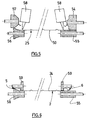
- the respective hollow-beam longitudinal portions 5, 6 of two adjacent panels 1 have complementary shapes and are thus able to cooperate to allow the rotational movement of one panel relative to the other. , and provide partial overlap of two adjacent panels in the junction area.
- the longitudinal portion upper 5 of the lower panel 1 is partially housed in the recess located below the third portion 20 of the lower longitudinal portion 6 of the upper panel 1.
- the structure that has just been described is such that two adjacent panels 1 of the leaf 28 closed are separated visually and externally only by a very small space between the curved area 19 of the lower longitudinal portion in the form of hollow beam 6 and the second portion 9 of the upper hollow beam-shaped longitudinal portion 5.
- This narrow space in the vertical direction is shallow in the horizontal direction which does not detract from the aesthetics of the door.
- the portion 9 of the upper longitudinal portion in the form of hollow beam is strongly inclined so that rainwater or cleaning as well as dust can not stagnate or incrust. It also contributes to the quality of the door.
- the arrangement is anti finger forceps.
- the longitudinal seal 15a fixed in the recess 15 formed by the recess in the form of an open-out cavity provided on the upper longitudinal portion in the form of hollow beam 5 works by compression against the second portion 18 placed opposite and little removed from the lower longitudinal part in the form of hollow beam 6. This is particularly effective.
- a sufficient clearance is provided between the longitudinal portions 5, 6 facing two adjacent panels to allow relative unobstructed rotation of one of the panels 1 relative to each other.
- the articulation of the two parts of the hinge 33 is located in the vicinity of the substantially horizontal plane defined by the housing 15 of the upper hollow-beam-shaped longitudinal portion 5 and the curved zone 19 of the hollow-beam-shaped lower longitudinal portion 6 This provision contributes to efficiency.
- the hinges 33 fixed on the reinforcing elements 26 situated in the vicinity of an edge 3, 4 comprise roller supports 36.
- the panels 1 are arranged so that the face 24 of the central strip 2 from which protrude the longitudinal hollow beam-shaped portions 5, 6 is located towards the inside I of the construction.
Landscapes
- Engineering & Computer Science (AREA)
- Civil Engineering (AREA)
- Structural Engineering (AREA)
- Wing Frames And Configurations (AREA)
Priority Applications (1)
| Application Number | Priority Date | Filing Date | Title |
|---|---|---|---|
| EP05290991A EP1722065A1 (de) | 2005-05-09 | 2005-05-09 | Platte mit Hohlprofilträgern zum aussteifen |
Applications Claiming Priority (1)
| Application Number | Priority Date | Filing Date | Title |
|---|---|---|---|
| EP05290991A EP1722065A1 (de) | 2005-05-09 | 2005-05-09 | Platte mit Hohlprofilträgern zum aussteifen |
Publications (1)
| Publication Number | Publication Date |
|---|---|
| EP1722065A1 true EP1722065A1 (de) | 2006-11-15 |
Family
ID=35058375
Family Applications (1)
| Application Number | Title | Priority Date | Filing Date |
|---|---|---|---|
| EP05290991A Withdrawn EP1722065A1 (de) | 2005-05-09 | 2005-05-09 | Platte mit Hohlprofilträgern zum aussteifen |
Country Status (1)
| Country | Link |
|---|---|
| EP (1) | EP1722065A1 (de) |
Cited By (2)
| Publication number | Priority date | Publication date | Assignee | Title |
|---|---|---|---|---|
| US7955460B2 (en) | 2008-05-02 | 2011-06-07 | Overhead Door Corporation | Movable barriers having transverse stiffeners and methods of making the same |
| CN112952604A (zh) * | 2019-12-10 | 2021-06-11 | 滨州市通联电器有限公司 | 一种具有多重防护结构的装配式电控箱及其制造方法 |
Citations (4)
| Publication number | Priority date | Publication date | Assignee | Title |
|---|---|---|---|---|
| DE3922981A1 (de) * | 1988-11-25 | 1990-05-31 | Hoermann Kg | Torblatt |
| DE4227311A1 (de) | 1992-08-18 | 1994-02-24 | Erich Doering | Paneel für ein Decken- oder Seitensektionaltor |
| US5782283A (en) * | 1997-04-03 | 1998-07-21 | Raynor Garage Doors | Garage door construction |
| EP0943776A1 (de) * | 1998-03-20 | 1999-09-22 | Novoferm France | Für ein Sektionaltor bestimmtes Paneel, Sektionaltor und seine Konditionierung |
-
2005
- 2005-05-09 EP EP05290991A patent/EP1722065A1/de not_active Withdrawn
Patent Citations (4)
| Publication number | Priority date | Publication date | Assignee | Title |
|---|---|---|---|---|
| DE3922981A1 (de) * | 1988-11-25 | 1990-05-31 | Hoermann Kg | Torblatt |
| DE4227311A1 (de) | 1992-08-18 | 1994-02-24 | Erich Doering | Paneel für ein Decken- oder Seitensektionaltor |
| US5782283A (en) * | 1997-04-03 | 1998-07-21 | Raynor Garage Doors | Garage door construction |
| EP0943776A1 (de) * | 1998-03-20 | 1999-09-22 | Novoferm France | Für ein Sektionaltor bestimmtes Paneel, Sektionaltor und seine Konditionierung |
Cited By (3)
| Publication number | Priority date | Publication date | Assignee | Title |
|---|---|---|---|---|
| US7955460B2 (en) | 2008-05-02 | 2011-06-07 | Overhead Door Corporation | Movable barriers having transverse stiffeners and methods of making the same |
| US8220519B2 (en) | 2008-05-02 | 2012-07-17 | Overhead Door Corporation | Movable barriers having transverse stiffeners and methods of making the same |
| CN112952604A (zh) * | 2019-12-10 | 2021-06-11 | 滨州市通联电器有限公司 | 一种具有多重防护结构的装配式电控箱及其制造方法 |
Similar Documents
| Publication | Publication Date | Title |
|---|---|---|
| EP2463470B1 (de) | Rahmen für Wände | |
| BE512172A (de) | ||
| EP1035297B1 (de) | Rolladenkasten, Seitenteil und Abdeckprofil für den Kasten | |
| WO1991001427A1 (fr) | Porte a plusieurs vantaux coulissants | |
| FR2800437A1 (fr) | Ensemble constitue d'un support rigide et d'un habillage du support, profile d'habillage et son utilisation pour un tel ensemble | |
| EP0943777B1 (de) | Vormontiertes und voreingestelltes Sektionaltor, und seine Konditionierung | |
| EP2053189B1 (de) | Rahmen mit Fenster- oder Türflügel | |
| EP1201869B1 (de) | Kunststoffflügel, sowie sein Herstellungsverfahren und zweiflügelige Öffnung, z.B. für ein Fenster | |
| EP1369549B1 (de) | Selbsttragendes Türblatt für ein Kipptor | |
| EP0669445B1 (de) | Profilstab für einen Vorhang und Möbel mit einem derartigen Vorhang | |
| EP0791700A1 (de) | Befestigungshalterung und Abstandhalter zur Erstellung von Verkleidungen im Bausektor, und so hergestellte Verkleidungen | |
| FR2753227A1 (fr) | Chassis de fermeture pour batiment, type fenetre ou porte-fenetre vitree, a frappe, a ouvrant(s) cache(s) | |
| EP1396603B1 (de) | Sektionaltorblatt und damit versehenes Tor | |
| FR3032221A1 (fr) | Combinaison de profile parclose et de profile d'ouvrant en vue de la realisation de chassis d'ouvrant de fenetre et porte fenetre et procede de realisation d'ouvrants | |
| FR2516585A1 (fr) | Huisserie metallique en tole pliee assemblee par equerres | |
| FR2641809A1 (fr) | Dispositif d'assemblage pour ossature de cloisons | |
| FR2539336A1 (fr) | Cabine de peinture en panneaux modulaires | |
| FR2967443A1 (fr) | Huisserie pour porte ou fenetre composee de deux plaques de platre | |
| WO2022189348A1 (fr) | Coulisse de fixation de rideau metallique, en particulier de rideau metallique anti-cyclonique | |
| FR2705379A3 (fr) | Joint pour façade d'immeuble ou autre, notamment à paroi vitrée. | |
| FR3166160A1 (fr) | Ouvrant vitré de menuiserie, menuiserie comprenant un tel ouvrant et procede de fabrication d’un tel ouvrant | |
| FR3160721A1 (fr) | Coffre de volet roulant comprenant une structure longitudinale de renfort intérieure | |
| EP1830027A1 (de) | Rahmenelement, das einen Glasteil aufnehmen kann, und entsprechendes Element mit Glasfunktion | |
| FR2637013A1 (fr) | Ensemble de porte coulissante et procede de fabrication | |
| FR2691236A1 (fr) | Elément incorporable pour des ouvertures pratiquées dans la paroi extérieure d'une construction. |
Legal Events
| Date | Code | Title | Description |
|---|---|---|---|
| PUAI | Public reference made under article 153(3) epc to a published international application that has entered the european phase |
Free format text: ORIGINAL CODE: 0009012 |
|
| AK | Designated contracting states |
Kind code of ref document: A1 Designated state(s): AT BE BG CH CY CZ DE DK EE ES FI FR GB GR HU IE IS IT LI LT LU MC NL PL PT RO SE SI SK TR |
|
| AX | Request for extension of the european patent |
Extension state: AL BA HR LV MK YU |
|
| RIN1 | Information on inventor provided before grant (corrected) |
Inventor name: GUITTON, CHRISTOPHE Inventor name: ROBIN, LAURENT |
|
| AKX | Designation fees paid |
Designated state(s): AT BE BG CH CY CZ DE DK EE ES FI FR GB GR HU IE IS IT LI LT LU MC NL PL PT RO SE SI SK TR |
|
| STAA | Information on the status of an ep patent application or granted ep patent |
Free format text: STATUS: THE APPLICATION IS DEEMED TO BE WITHDRAWN |
|
| 18D | Application deemed to be withdrawn |
Effective date: 20070516 |