EP1722209A1 - Druckwandler für gasförmige Wasserstoffumgebung - Google Patents
Druckwandler für gasförmige Wasserstoffumgebung Download PDFInfo
- Publication number
- EP1722209A1 EP1722209A1 EP06075914A EP06075914A EP1722209A1 EP 1722209 A1 EP1722209 A1 EP 1722209A1 EP 06075914 A EP06075914 A EP 06075914A EP 06075914 A EP06075914 A EP 06075914A EP 1722209 A1 EP1722209 A1 EP 1722209A1
- Authority
- EP
- European Patent Office
- Prior art keywords
- container
- oil
- hydrogen
- sensor
- pressure sensor
- Prior art date
- Legal status (The legal status is an assumption and is not a legal conclusion. Google has not performed a legal analysis and makes no representation as to the accuracy of the status listed.)
- Granted
Links
Images

Classifications
-
- H—ELECTRICITY
- H01—ELECTRIC ELEMENTS
- H01M—PROCESSES OR MEANS, e.g. BATTERIES, FOR THE DIRECT CONVERSION OF CHEMICAL ENERGY INTO ELECTRICAL ENERGY
- H01M8/00—Fuel cells; Manufacture thereof
- H01M8/04—Auxiliary arrangements, e.g. for control of pressure or for circulation of fluids
- H01M8/04082—Arrangements for control of reactant parameters, e.g. pressure or concentration
- H01M8/04089—Arrangements for control of reactant parameters, e.g. pressure or concentration of gaseous reactants
-
- G—PHYSICS
- G01—MEASURING; TESTING
- G01L—MEASURING FORCE, STRESS, TORQUE, WORK, MECHANICAL POWER, MECHANICAL EFFICIENCY, OR FLUID PRESSURE
- G01L19/00—Details of, or accessories for, apparatus for measuring steady or quasi-steady pressure of a fluent medium insofar as such details or accessories are not special to particular types of pressure gauges
- G01L19/06—Means for preventing overload or deleterious influence of the measured medium on the measuring device or vice versa
- G01L19/0627—Protection against aggressive medium in general
- G01L19/0645—Protection against aggressive medium in general using isolation membranes, specially adapted for protection
-
- G—PHYSICS
- G01—MEASURING; TESTING
- G01L—MEASURING FORCE, STRESS, TORQUE, WORK, MECHANICAL POWER, MECHANICAL EFFICIENCY, OR FLUID PRESSURE
- G01L19/00—Details of, or accessories for, apparatus for measuring steady or quasi-steady pressure of a fluent medium insofar as such details or accessories are not special to particular types of pressure gauges
- G01L19/06—Means for preventing overload or deleterious influence of the measured medium on the measuring device or vice versa
- G01L19/0627—Protection against aggressive medium in general
- G01L19/0654—Protection against aggressive medium in general against moisture or humidity
-
- H—ELECTRICITY
- H01—ELECTRIC ELEMENTS
- H01M—PROCESSES OR MEANS, e.g. BATTERIES, FOR THE DIRECT CONVERSION OF CHEMICAL ENERGY INTO ELECTRICAL ENERGY
- H01M8/00—Fuel cells; Manufacture thereof
- H01M8/10—Fuel cells with solid electrolytes
- H01M2008/1095—Fuel cells with polymeric electrolytes
-
- Y—GENERAL TAGGING OF NEW TECHNOLOGICAL DEVELOPMENTS; GENERAL TAGGING OF CROSS-SECTIONAL TECHNOLOGIES SPANNING OVER SEVERAL SECTIONS OF THE IPC; TECHNICAL SUBJECTS COVERED BY FORMER USPC CROSS-REFERENCE ART COLLECTIONS [XRACs] AND DIGESTS
- Y02—TECHNOLOGIES OR APPLICATIONS FOR MITIGATION OR ADAPTATION AGAINST CLIMATE CHANGE
- Y02E—REDUCTION OF GREENHOUSE GAS [GHG] EMISSIONS, RELATED TO ENERGY GENERATION, TRANSMISSION OR DISTRIBUTION
- Y02E60/00—Enabling technologies; Technologies with a potential or indirect contribution to GHG emissions mitigation
- Y02E60/30—Hydrogen technology
- Y02E60/50—Fuel cells
Definitions
- This disclosure relates generally to pressure sensors. More particularly, this disclosure relates to pressure sensors for use in hydrogen-rich environments.
- Certain vehicle control systems involve measuring pressure parameters, such as engine oil pressure, fuel pressure, transmission fluid pressure, or brake pressure.
- Silicon-based pressure sensors for example, are used in a wide variety of automotive applications, including sensing manifold absolute pressure (MAP), turbo intake air pressure, and differential fuel vapor pressure.
- MAP manifold absolute pressure
- turbo intake air pressure turbo intake air pressure
- differential fuel vapor pressure differential fuel vapor pressure
- Some silicon-based pressure sensors work by sensing a differential pressure across a thin silicon membrane or diaphragm within a cell body.
- the silicon membrane and cell body form a cavity that is hermetically sealed under a vacuum. This cavity establishes a reference pressure on one side of the membrane.
- the pressure sensor outputs a voltage that is proportional to the difference in pressure between the sensed pressure and the reference pressure.
- the cell body and corresponding package must be able to withstand the environment.
- the silicon membrane of the pressure sensor For absolute pressure sensing applications involving hydrogen gas media, for example, in proton exchange membrane (PEM) hydrogen fuel cells, it can be difficult for the silicon membrane of the pressure sensor to maintain a differential pressure.
- PEM proton exchange membrane
- maintaining a reference vacuum in the cavity formed by the silicon membrane and the cell body is difficult because hydrogen diffuses or permeates through the silicon.
- the rate at which this diffusion or permeation occurs can be significant over long periods of time at temperatures commonly found in automotive environments.
- the reference vacuum can fill with hydrogen over time. When the reference vacuum fills with hydrogen, the accuracy of the absolute pressure sensor can deviate from acceptable limits.
- a silicon-based hydrogen pressure sensor module incorporates a substrate formed from a low temperature cofired ceramic (LTCC) or other suitable material.
- a container filled with an incompressible liquid, such as oil is mounted on the substrate and houses a sensor cell.
- the oil is impregnated with a hydrogen getter material or has high intrinsic hydrogen gettering properties.
- the substrate or the container, or both shields the cavity formed by the silicon membrane and cell body from hydrogen permeation.
- One embodiment is directed to a sensor assembly having a ceramic substrate.
- a container is located on the ceramic substrate.
- the container and the ceramic substrate define a container volume.
- a sensor cell is located within the container volume.
- the sensor cell comprises a sensor handle wafer and a diaphragm proximate the sensor handle wafer.
- the sensor cell defines a reference cavity.
- a substantially incompressible liquid is disposed within the container volume.
- the substantially incompressible liquid comprises a hydrogen getter material.
- a pressure sensor arrangement in another embodiment, includes a ceramic substrate and a container located on the ceramic substrate.
- the container has a boss formed on a surface of the container.
- the container and the ceramic substrate define a container volume.
- a silicon pressure sensor handle wafer is located within the container volume.
- a silicon diaphragm is located within the container volume and is attached to the silicon pressure sensor handle wafer so as to define a reference cavity located between the silicon diaphragm and the silicon pressure sensor handle wafer.
- An oil material comprising a hydrogen getter material is disposed within the container volume.
- the pressure sensor arrangement may be incorporated in a fuel cell system including a fuel cell and a hydrogen source in gaseous communication with the fuel cell via a hydrogen supply path.
- a control subsystem is configured to regulate the flow of hydrogen to the fuel cell via the hydrogen supply path.
- a substrate material is provided.
- a plurality of containers are located on the substrate material in an array arrangement.
- the containers and the substrate material define a plurality of container volumes.
- a sensor cell is formed within each container volume.
- Each sensor cell comprises a sensor handle wafer and a diaphragm proximate the sensor handle wafer.
- the sensor cell defines a reference cavity.
- a plurality of ports are formed in the substrate material.
- a substantially incompressible liquid is introduced within the container volumes via the ports.
- the substantially incompressible liquid comprises a hydrogen getter material. In this way, the plurality of sensor assemblies are formed in the array arrangement.
- the container may reduce hydrogen permeation to the reference cavity.
- the hydrogen getter-impregnated oil filling the container volume may further reduce hydrogen permeation, while transferring pressure from the bossed can surface to the diaphragm. With hydrogen permeation reduced, the performance of the pressure sensor can be maintained within acceptable limits.
- a silicon-based hydrogen pressure sensor module incorporates a substrate formed from a low temperature cofired ceramic (LTCC) or other suitable material.
- a container filled with an incompressible liquid, such as oil is mounted on the substrate and houses a sensor cell.
- the oil material is impregnated with a hydrogen getter material or has high intrinsic hydrogen gettering properties.
- the substrate or the container, or both shields the reference cavity formed by the silicon membrane and cell body from hydrogen permeation.
- Hydrogen permeation to the reference cavity may be reduced in a number of ways.
- the container may reduce hydrogen permeation to the reference cavity.
- the hydrogen getter-impregnated oil filling the container volume may further reduce hydrogen permeation, while transferring pressure from the can surface to the diaphragm. With hydrogen permeation reduced, the performance of the pressure sensor can be maintained within acceptable limits.
- FIG. 1 illustrates an example hydrogen pressure sensor assembly 100 according to one embodiment.
- the hydrogen pressure sensor assembly 100 may measure pressures in any of a variety of ranges, including, for example, a manifold absolute pressure (MAP) range up to about 1 atmosphere, a turbo pressure range from about 1-5 atmospheres, and higher pressures, upwards of about 700 atmospheres.
- the hydrogen pressure sensor assembly 100 includes a stainless steel can 102 mounted on a substrate 104.
- the can 102 may be formed from another appropriate metal, such as aluminum or alloy 42.
- the substrate 104 may be formed from a ceramic material such as a low temperature cofired ceramic (LTCC), a polymer-based material such as FR-4, or other suitable material.
- LTCC low temperature cofired ceramic
- FR-4 polymer-based material
- the can 102 is soldered to the substrate 104.
- the can 102 may be bonded to the substrate 104 by other means, for example, using any of a variety of adhesives and epoxies. These adhesives and epoxies may be either electrically conductive or electrically nonconductive.
- the can 102 and the substrate 104 define a container volume 106.
- an incompressible liquid for example, silicone or other oil
- an incompressible liquid for example, silicone or other oil
- Other oil materials that can be used include, but are not limited to, fluorinated oil, low-temperature oil, and biocompatible oils.
- the oil material is suitable for use in hydrogen-rich environments and provides general media compatibility.
- the port 108 can be formed in the substrate 104, as shown in Figure 1, or can be formed on a wall of the can 102.
- the oil material may be introduced into the container volume 106, for example, using a pinched and welded filling tube or other filling mechanism.
- Other filling mechanisms may involve horizontal and vertical port arrangements formed in the substrate 104 that allow the oil to be provided in plate form to many cells simultaneously, e.g., in an array or many-up manufacturing configuration.
- an array, or many-up, manufacturing configuration can be realized.
- This type of manufacturing configuration facilitates the simultaneous manufacture of hydrogen pressure sensors in a manner analogous to the manufacture of silicon wafers containing many dies arranged in an array-like configuration.
- hydrogen pressure sensors manufactured in a many-up configuration using LTCC or another suitable substrate material are subjected to hydrogen pressure testing in a many-up configuration on the manufacturing line.
- a sensor cell 110 is located within the container volume 106.
- the sensor cell includes a hydrogen pressure sensor handle wafer 112, which may be implemented, for example, as a silicon piezoresistive pressure sensor or other suitable pressure sensor.
- a depression is formed on a surface 114 of the hydrogen pressure sensor handle wafer 112.
- a silicon piezoresistive diaphragm 116 is bonded or otherwise attached to the hydrogen pressure sensor handle wafer 112 at interfaces 118.
- the diaphragm 116 and the hydrogen pressure sensor handle wafer 112 define a reference cavity 120, which is formed as a vacuum.
- the reference cavity 120 be at least substantially preserved as a vacuum.
- the vacuum of the reference cavity can be compromised by hydrogen permeation.
- the pressure sensor,assembly 100 illustrated in Figure 1 protects the reference cavity 120 from hydrogen permeation via a number of routes, which are indicated by dotted arrows in Figure 1.
- bosses 122 significantly decrease the hydrogen permeation rate through a top surface 124 of the can 102 via a route 126.
- the oil material has high intrinsic hydrogen-gettering properties or is impregnated with a hydrogen getter material, such as a suitable palladium alloy or a commercially available hydrogen getter material.
- a hydrogen getter material such as a suitable palladium alloy or a commercially available hydrogen getter material.
- the hydrogen getter material absorbs some of the hydrogen that does pass through the top surface 124 of the can 102. In this way, the hydrogen getter material decreases the hydrogen permeation rate through the diaphragm 116 via a route 128.
- the hydrogen getter material also decreases the hydrogen permeation rate along the interface 118 between the diaphragm 116 and the hydrogen pressure sensor handle wafer 112 via a route 130. Further, the hydrogen getter material also decreases the hydrogen permeation rate through the diaphragm 116 itself via a route 132.
- the getter-impregnated oil material significantly retards the permeation of hydrogen into the reference cavity 120 via routes 126, 128, 130, and 132, thereby substantially preserving the integrity of the vacuum in the reference cavity 120 and prolonging the useful life of the pressure sensor assembly 100.
- the substrate 104 may be formed from LTCC.
- LTCC is suitable for use in high pressure and hydrogen-rich environments. Additionally, using LTCC facilitates adding integrated circuit (IC) components, discrete components, and internal components such as buried capacitors or internal cavities and channels, i.e., plumbing.
- the substrate 104 may be formed from a ceramic, polymer-based FR-4, or some other suitable material. While not illustrated in Figure 1, the substrate 104 may be populated by discrete components, integrated circuit (IC) components, or both to create a one-piece module suitable for use in high pressures and other harsh environments.
- FIG. 2 is a block diagram illustrating an example fuel cell system 200 incorporating the hydrogen pressure sensor assembly 100 of Figure 1.
- a fuel cell 202 generates the power that is provided by the fuel cell system 200.
- the fuel cell 202 may be implemented, for example, as a proton exchange membrane fuel cell (PEMFC), and has an anode 204 and a cathode 206.
- Hydrogen is supplied to the anode 204 from a hydrogen source 208, such as a pressurized hydrogen tank, via a hydrogen supply path 210.
- Oxygen is supplied to the cathode 206 from an oxygen source, such as an air supply subsystem 212, via an oxygen supply path 214.
- a control subsystem 216 controls the delivery of hydrogen and oxygen to the fuel cell 202.
- the control subsystem 216 controls the delivery of hydrogen to the anode 204 by operation of a cutoff valve 218.
- a regulator 220 further controls the delivery of hydrogen to the anode 204 to ensure that the pressure of the hydrogen at the output of the regulator 220 is within a prescribed range of pressures.
- a pressure sensor 222 is located along the hydrogen supply path 210 and measures the pressure of hydrogen flowing through the hydrogen supply path 210.
- the pressure sensor 222 may incorporate the pressure sensor assembly 100, which is described in greater detail above in connection with Figure 1.
- a temperature sensor 224 is also located along the hydrogen supply path 210 and measures the temperature of the hydrogen flowing through the hydrogen supply path 210.
- the control subsystem 216 receives signals from the pressure sensor 222 and the temperature sensor 224 indicating the pressure and temperature, respectively, of the hydrogen gas flowing through the hydrogen supply path 210.
- the control subsystem 216 adjusts the flow of hydrogen gas as appropriate by controlling the operation of the cutoff valve 218.
- Figure 1 illustrates a general absolute pressure sensor assembly.
- a differential hydrogen pressure sensor can be implemented by using a differential silicon pressure sensor cell that has appropriate ports formed in the pressure sensor assembly.
- Such ports may include, for example, a port similar to the port 108 shown in Figure 1.
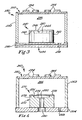
- FIG 3 is a sectional view illustrating an example hydrogen pressure sensor assembly 230 according to another embodiment.
- the hydrogen pressure sensor assembly 230 includes a stainless steel can 232 mounted on a substrate 234.
- the can 232 may be formed from another appropriate metal, such as aluminum or alloy 42.
- the substrate 234 may be formed from a ceramic material such as LTCC, a polymer-based material such as FR-4, or another suitable material.
- the can 232 is soldered to the substrate 234.
- the can 232 may be bonded to the substrate 234 by other means, for example, using any of a variety of adhesives and epoxies. These adhesives and epoxies may be either electrically conductive or electrically nonconductive.
- the can 232 and the substrate 234 define a container volume 236.
- an oil such as silicone
- Other oils include, but are not limited to, fluorinated oil, low-temperature oil, and biocompatible oils.
- the oil is suitable for use in hydrogen-rich environments and provides general media compatibility.
- the oil material has high intrinsic hydrogen-gettering properties or is impregnated with a hydrogen getter material, such as a suitable palladium alloy or a commercially available hydrogen getter material.
- a hydrogen getter material such as a suitable palladium alloy or a commercially available hydrogen getter material.
- the intrinsically hydrogen-gettering or getter-impregnated oil material significantly retards the permeation of hydrogen into the reference cavity, thereby substantially preserving the integrity of the vacuum in the reference cavity and prolonging the useful life of the hydrogen pressure sensor assembly 230.
- an internal plumbing system of substantially orthogonal ports 238 is formed in the substrate 234. This arrangement of ports 238 is suitable for manufacturing multiple pressure sensor assemblies 230 in an array or many-up manufacturing configuration because it allows the oil to be introduced into multiple pressure sensor assemblies 230 from a single source.
- the oil may be introduced into the container volume 236, for example, using a pinched and welded filling tube or other filling mechanism.
- an array, or many-up, manufacturing configuration can be realized.
- This type of manufacturing configuration facilitates the simultaneous manufacture of pressure sensors in a manner analogous to the manufacture of silicon wafers containing many dies arranged in an array-like configuration.
- hydrogen pressure sensors manufactured in a many-up configuration using LTCC or another suitable substrate material are subjected to pressure testing in a many-up configuration on the manufacturing line.
- a sensor cell 240 is located within the container volume 236.
- the sensor cell includes a pressure sensor handle wafer 242, which may be implemented, for example, as a silicon piezoresistive pressure sensor or other suitable pressure sensor.
- a depression is formed on a surface 244 of the pressure sensor handle wafer 242.
- a diaphragm 246 is bonded or otherwise attached to the pressure sensor handle wafer 242 at interfaces 248.
- the diaphragm 246 and the pressure sensor handle wafer 242 define a reference cavity 250, which is formed as a vacuum.
- the diaphragm 246 may be protected from potential adverse effects of high pressure, as well as hydrogen-rich environments.
- the can 232 may have a top surface 252 that incorporates a flexible membrane that deflects under pressure. By controlling the surface area and thickness of the flexible membrane, the diaphragm 246 can be configured to measure a wide range of pressures.
- bosses 254 may be formed on the top surface 252.
- the bosses 254 may be used to help control the response of the top surface 252 to pressure.
- the oil in the container volume 236 provides the mechanism for transferring the pressure from the top surface 252 to the diaphragm 246. This arrangement may be compatible with difficult sensing environments, such as environments in which brake fluid pressure is sensed.
- the can 232 protects the diaphragm 246 from harsh effects of the environment, while the controlled response of the top surface 252 and the oil in the container volume 236 allow the pressure of the environment to be sensed.
- the oil also protects the diaphragm 246 from harsh media by reducing or eliminating direct exposure of the diaphragm 246 to the media.
- the substrate 234 may be formed from LTCC.
- LTCC is suitable for use in high pressure, as well as hydrogen-rich environments. Additionally, using LTCC facilitates adding IC components, discrete components, and internal components such as buried capacitors or internal cavities and channels, i.e., plumbing.
- the substrate 234 may be formed from a ceramic, FR-4, or some other suitable material. While not illustrated in Figure 3, the substrate 234 may be populated by discrete components, IC components, or both to create a one-piece module suitable for use in high pressures and hydrogen-rich environments.
- FIG. 4 is a sectional view illustrating an example differential hydrogen pressure sensor assembly 260 according to yet another embodiment.
- the differential hydrogen pressure sensor assembly 260 includes a stainless steel can 262 mounted on a substrate 264.
- the can 262 may be formed from another appropriate metal, such as aluminum or alloy 42.
- the substrate 264 may be formed from LTCC or another ceramic material, FR-4, or another suitable material.
- the can 262 is soldered to the substrate 264.
- the can 262 may be bonded to the substrate 264 by other means, for example, using any of a variety of adhesives and epoxies. These adhesives and epoxies may be either electrically conductive or electrically nonconductive.
- the can 262 and the substrate 264 define a container volume 266.
- an oil such as silicone
- Other oils that can be used include, but are not limited to, fluorinated oil, low-temperature oil, and biocompatible oils.
- the oil is suitable for use in high pressure and hydrogen-rich environments and provides general media compatibility.
- the oil may be introduced into the container volume 266, for example, using a pinched and welded filling tube or other filling mechanism.
- the oil material has high intrinsic hydrogen-gettering properties or is impregnated with a hydrogen getter material, such as a suitable palladium alloy or a commercially available hydrogen getter material.
- the intrinsically hydrogen-gettering or getter-impregnated oil material significantly retards the permeation of hydrogen into the reference cavity, thereby substantially preserving the integrity of the vacuum in the reference cavity and prolonging the useful life of the differential hydrogen pressure sensor assembly 260.
- a sensor cell 270 is located within the container volume 266.
- the sensor cell includes a pressure sensor handle wafer 272, which may be implemented, for example, as a silicon piezoresistive pressure sensor or other suitable pressure sensor.
- a depression is formed on a surface 274 of the pressure sensor handle wafer 272.
- a diaphragm 276 is bonded or otherwise attached to the pressure sensor handle wafer 272 at interfaces 278.
- a differential port 280 is formed within the pressure sensor handle wafer 272 and the substrate 264 and beneath the diaphragm 276. In operation, the differential pressure sensor assembly 260 measures the differential pressure between the ambient environment and another environment in communication with the differential port 280.
- the diaphragm 276 may be protected from potential adverse effects of high pressure, as well as hydrogen-rich environments.
- the can 272 may have a top surface 282 that incorporates a flexible membrane that deflects under pressure. By controlling the surface area and thickness of the flexible membrane, the diaphragm 276 can be configured to measure a wide range of pressures.
- bosses 284 may be formed on the top surface 282.
- the bosses 284 may be used to help control the response of the top surface 282 to pressure.
- the oil in the container volume 266 provides the mechanism for transferring the pressure from the top surface 282 to the diaphragm 276. This arrangement may be compatible with difficult sensing environments, such as environments in which brake fluid pressure is sensed.
- the can 262 protects the diaphragm 276 from harsh effects of the environment, while the controlled response of the top surface 282 and the oil in the container volume 266 allow the pressure of the environment to be sensed.
- the oil also protects the diaphragm 276 from harsh media by reducing or eliminating direct exposure of the diaphragm 276 to the media.
- the substrate 264 may be formed from LTCC.
- LTCC is suitable for use in hydrogen-rich and high pressure environments. Additionally, using LTCC facilitates adding IC components, discrete components, and internal components such as buried capacitors or internal cavities and channels, i.e., plumbing.
- the substrate 264 may be formed from a ceramic, FR-4, or some other suitable material. While not illustrated in Figure 4, the substrate 264 may be populated by discrete components, IC components, or both to create a one-piece module suitable for use in high pressures and hydrogen-rich environments.
- Hydrogen permeation to the reference cavity may be reduced in a number of ways.
- the bossed container may reduce hydrogen permeation to the reference cavity.
- the hydrogen getter-impregnated oil filling the container volume may further reduce hydrogen permeation, while transferring pressure from the bossed can surface to the diaphragm.
- the performance of the pressure sensor can be maintained within acceptable limits.
- the electrical components of the pressure sensor can be protected from potential adverse effects from a hydrogen fuel cell environment.
Landscapes
- Physics & Mathematics (AREA)
- General Physics & Mathematics (AREA)
- Sustainable Energy (AREA)
- Engineering & Computer Science (AREA)
- Manufacturing & Machinery (AREA)
- Sustainable Development (AREA)
- Life Sciences & Earth Sciences (AREA)
- Chemical & Material Sciences (AREA)
- Chemical Kinetics & Catalysis (AREA)
- Electrochemistry (AREA)
- General Chemical & Material Sciences (AREA)
- Measuring Fluid Pressure (AREA)
- Hydrogen, Water And Hydrids (AREA)
- Crystals, And After-Treatments Of Crystals (AREA)
Applications Claiming Priority (1)
| Application Number | Priority Date | Filing Date | Title |
|---|---|---|---|
| US11/125,062 US7228744B2 (en) | 2005-05-09 | 2005-05-09 | Pressure transducer for gaseous hydrogen environment |
Publications (2)
| Publication Number | Publication Date |
|---|---|
| EP1722209A1 true EP1722209A1 (de) | 2006-11-15 |
| EP1722209B1 EP1722209B1 (de) | 2010-01-20 |
Family
ID=36754719
Family Applications (1)
| Application Number | Title | Priority Date | Filing Date |
|---|---|---|---|
| EP06075914A Expired - Lifetime EP1722209B1 (de) | 2005-05-09 | 2006-04-19 | Druckwandler für gasförmige Wasserstoffumgebung |
Country Status (4)
| Country | Link |
|---|---|
| US (1) | US7228744B2 (de) |
| EP (1) | EP1722209B1 (de) |
| AT (1) | ATE456032T1 (de) |
| DE (1) | DE602006011812D1 (de) |
Cited By (2)
| Publication number | Priority date | Publication date | Assignee | Title |
|---|---|---|---|---|
| WO2013176737A1 (en) * | 2012-05-22 | 2013-11-28 | Rosemount, Inc. | Pressure transmitter with hydrogen getter |
| CN104215389A (zh) * | 2013-05-31 | 2014-12-17 | 福建上润精密仪器有限公司 | 硅压力/差压变送器耐单向过载及工作压力结构 |
Families Citing this family (4)
| Publication number | Priority date | Publication date | Assignee | Title |
|---|---|---|---|---|
| JP6018945B2 (ja) * | 2012-10-05 | 2016-11-02 | 株式会社日立製作所 | 伝送装置及び伝送方法 |
| US10107315B2 (en) * | 2013-04-30 | 2018-10-23 | Mks Instruments, Inc. | MEMS pressure sensors with integrated baffles |
| JP6436033B2 (ja) * | 2015-09-22 | 2018-12-12 | 株式会社Soken | 水素圧力計測装置 |
| KR102554308B1 (ko) * | 2022-07-22 | 2023-07-11 | 삼회산업 (주) | 수소 압력 또는 가스 압력 측정이 가능한 극저온 방폭압력센서 |
Citations (6)
| Publication number | Priority date | Publication date | Assignee | Title |
|---|---|---|---|---|
| DE2630640A1 (de) * | 1975-07-08 | 1977-01-27 | Keller Hans W | Piezoresistive druckmesszelle |
| US5220838A (en) * | 1991-03-28 | 1993-06-22 | The Foxboro Company | Overpressure-protected, differential pressure sensor and method of making the same |
| EP0553725A2 (de) * | 1992-01-24 | 1993-08-04 | The Foxboro Company | Verfahren und Vorrichtung zur Herstellung eines Druckwandlers mit einem laminierten Substrat |
| US5661245A (en) * | 1995-07-14 | 1997-08-26 | Sensym, Incorporated | Force sensor assembly with integrated rigid, movable interface for transferring force to a responsive medium |
| EP1126260A1 (de) * | 1999-08-05 | 2001-08-22 | Fujikin Incorporated | Befestigungsanordnung eines drucksensor |
| US20020019711A1 (en) * | 2000-03-07 | 2002-02-14 | Haruzo Miyashita | Anticorrosive vacuum sensor |
Family Cites Families (6)
| Publication number | Priority date | Publication date | Assignee | Title |
|---|---|---|---|---|
| US5287746A (en) * | 1992-04-14 | 1994-02-22 | Rosemount Inc. | Modular transmitter with flame arresting header |
| US5438876A (en) * | 1993-08-05 | 1995-08-08 | The Foxboro Company | Modular diaphragm pressure sensor with peripheral mounted electrical terminals |
| WO1998012528A1 (fr) * | 1996-09-19 | 1998-03-26 | Hokuriku Electric Industry Co., Ltd. | Capteur de pression a capacite electrostatique |
| US6568274B1 (en) * | 1998-02-04 | 2003-05-27 | Mks Instruments, Inc. | Capacitive based pressure sensor design |
| US6893907B2 (en) * | 2002-06-05 | 2005-05-17 | Applied Materials, Inc. | Fabrication of silicon-on-insulator structure using plasma immersion ion implantation |
| US6991687B2 (en) * | 2001-07-27 | 2006-01-31 | Surface Combustion, Inc. | Vacuum carburizing with napthene hydrocarbons |
-
2005
- 2005-05-09 US US11/125,062 patent/US7228744B2/en not_active Expired - Lifetime
-
2006
- 2006-04-19 EP EP06075914A patent/EP1722209B1/de not_active Expired - Lifetime
- 2006-04-19 DE DE602006011812T patent/DE602006011812D1/de not_active Expired - Lifetime
- 2006-04-19 AT AT06075914T patent/ATE456032T1/de not_active IP Right Cessation
Patent Citations (6)
| Publication number | Priority date | Publication date | Assignee | Title |
|---|---|---|---|---|
| DE2630640A1 (de) * | 1975-07-08 | 1977-01-27 | Keller Hans W | Piezoresistive druckmesszelle |
| US5220838A (en) * | 1991-03-28 | 1993-06-22 | The Foxboro Company | Overpressure-protected, differential pressure sensor and method of making the same |
| EP0553725A2 (de) * | 1992-01-24 | 1993-08-04 | The Foxboro Company | Verfahren und Vorrichtung zur Herstellung eines Druckwandlers mit einem laminierten Substrat |
| US5661245A (en) * | 1995-07-14 | 1997-08-26 | Sensym, Incorporated | Force sensor assembly with integrated rigid, movable interface for transferring force to a responsive medium |
| EP1126260A1 (de) * | 1999-08-05 | 2001-08-22 | Fujikin Incorporated | Befestigungsanordnung eines drucksensor |
| US20020019711A1 (en) * | 2000-03-07 | 2002-02-14 | Haruzo Miyashita | Anticorrosive vacuum sensor |
Non-Patent Citations (1)
| Title |
|---|
| GHEZZI F ET AL: "Problems of determining true equilibrium pressures of hydrogen getters over a wide range of getter temperature and hydrogen sorption", JOURNAL OF VACUUM SCIENCE AND TECHNOLOGY A. VACUUM, SURFACES AND FILMS, AMERICAN INSTITUTE OF PHYSICS, NEW YORK, NY, US, vol. 17, no. 6, November 1999 (1999-11-01), pages 3452 - 3462, XP012004883, ISSN: 0734-2101 * |
Cited By (4)
| Publication number | Priority date | Publication date | Assignee | Title |
|---|---|---|---|---|
| WO2013176737A1 (en) * | 2012-05-22 | 2013-11-28 | Rosemount, Inc. | Pressure transmitter with hydrogen getter |
| US9057659B2 (en) | 2012-05-22 | 2015-06-16 | Rosemount Inc. | Pressure transmitter with hydrogen getter |
| CN104215389A (zh) * | 2013-05-31 | 2014-12-17 | 福建上润精密仪器有限公司 | 硅压力/差压变送器耐单向过载及工作压力结构 |
| CN104215389B (zh) * | 2013-05-31 | 2016-08-10 | 福建上润精密仪器有限公司 | 硅压力/差压变送器耐单向过载及工作压力结构 |
Also Published As
| Publication number | Publication date |
|---|---|
| US7228744B2 (en) | 2007-06-12 |
| EP1722209B1 (de) | 2010-01-20 |
| DE602006011812D1 (de) | 2010-03-11 |
| US20060248958A1 (en) | 2006-11-09 |
| ATE456032T1 (de) | 2010-02-15 |
Similar Documents
| Publication | Publication Date | Title |
|---|---|---|
| US7421773B2 (en) | Method of making pressure sensor assemblies | |
| CN103424223B (zh) | 具有氢吸气剂的压力变送器 | |
| JP2005524848A (ja) | 気圧センサ | |
| US7228744B2 (en) | Pressure transducer for gaseous hydrogen environment | |
| JP2009031003A (ja) | デュアル圧力センサ | |
| US7043960B1 (en) | Self-calibrating pressure transducer | |
| US20260098845A1 (en) | Gas sensor with a sensor element and a flame arrester and use of the same for the detection of gases | |
| EP0677727A2 (de) | Druckwandler-Montage und Herstellungsverfahren dazu | |
| US20220260538A1 (en) | Gas sensor having a hollow space and a gas permeation structure having a selectively gas-permeable element | |
| US12392744B2 (en) | Sensor for measuring a gas property | |
| CN220170418U (zh) | 一种表压传感器 | |
| CN220170420U (zh) | 一种表压传感器 | |
| EP3814737B1 (de) | Vakuumbeständige drucksensorvorrichtung | |
| CN115248098A (zh) | 泄漏测试标准器及泄漏测试系统 | |
| CN218330468U (zh) | 泄漏测试标准器及泄漏测试系统 | |
| US10247632B2 (en) | Oil filled gage reference side protection | |
| US8168345B2 (en) | Device and method for operation of a fuel cell | |
| US20260118301A1 (en) | Sensor for measuring a gas property | |
| CN217786466U (zh) | 膜电极气密测试设备 | |
| CN221173542U (zh) | 一种真空塑封型净水机压力变送器 | |
| JP2023160773A (ja) | 流体部品および流体監視システム。 | |
| CN118425427A (zh) | 一种氧检测主机测试系统及方法 | |
| CN121720660A (zh) | 一种气体泄漏检测装置 | |
| Lueck | Self-Calibrating Pressure Transducer |
Legal Events
| Date | Code | Title | Description |
|---|---|---|---|
| PUAI | Public reference made under article 153(3) epc to a published international application that has entered the european phase |
Free format text: ORIGINAL CODE: 0009012 |
|
| AK | Designated contracting states |
Kind code of ref document: A1 Designated state(s): AT BE BG CH CY CZ DE DK EE ES FI FR GB GR HU IE IS IT LI LT LU LV MC NL PL PT RO SE SI SK TR |
|
| AX | Request for extension of the european patent |
Extension state: AL BA HR MK YU |
|
| 17P | Request for examination filed |
Effective date: 20070515 |
|
| AKX | Designation fees paid |
Designated state(s): AT BE BG CH CY CZ DE DK EE ES FI FR GB GR HU IE IS IT LI LT LU LV MC NL PL PT RO SE SI SK TR |
|
| 17Q | First examination report despatched |
Effective date: 20070725 |
|
| GRAP | Despatch of communication of intention to grant a patent |
Free format text: ORIGINAL CODE: EPIDOSNIGR1 |
|
| GRAS | Grant fee paid |
Free format text: ORIGINAL CODE: EPIDOSNIGR3 |
|
| GRAA | (expected) grant |
Free format text: ORIGINAL CODE: 0009210 |
|
| AK | Designated contracting states |
Kind code of ref document: B1 Designated state(s): AT BE BG CH CY CZ DE DK EE ES FI FR GB GR HU IE IS IT LI LT LU LV MC NL PL PT RO SE SI SK TR |
|
| REG | Reference to a national code |
Ref country code: GB Ref legal event code: FG4D |
|
| REG | Reference to a national code |
Ref country code: CH Ref legal event code: EP |
|
| REG | Reference to a national code |
Ref country code: IE Ref legal event code: FG4D |
|
| REF | Corresponds to: |
Ref document number: 602006011812 Country of ref document: DE Date of ref document: 20100311 Kind code of ref document: P |
|
| REG | Reference to a national code |
Ref country code: NL Ref legal event code: VDEP Effective date: 20100120 |
|
| LTIE | Lt: invalidation of european patent or patent extension |
Effective date: 20100120 |
|
| PG25 | Lapsed in a contracting state [announced via postgrant information from national office to epo] |
Ref country code: AT Free format text: LAPSE BECAUSE OF FAILURE TO SUBMIT A TRANSLATION OF THE DESCRIPTION OR TO PAY THE FEE WITHIN THE PRESCRIBED TIME-LIMIT Effective date: 20100120 |
|
| PG25 | Lapsed in a contracting state [announced via postgrant information from national office to epo] |
Ref country code: PT Free format text: LAPSE BECAUSE OF FAILURE TO SUBMIT A TRANSLATION OF THE DESCRIPTION OR TO PAY THE FEE WITHIN THE PRESCRIBED TIME-LIMIT Effective date: 20100520 Ref country code: ES Free format text: LAPSE BECAUSE OF FAILURE TO SUBMIT A TRANSLATION OF THE DESCRIPTION OR TO PAY THE FEE WITHIN THE PRESCRIBED TIME-LIMIT Effective date: 20100501 Ref country code: LT Free format text: LAPSE BECAUSE OF FAILURE TO SUBMIT A TRANSLATION OF THE DESCRIPTION OR TO PAY THE FEE WITHIN THE PRESCRIBED TIME-LIMIT Effective date: 20100120 Ref country code: IS Free format text: LAPSE BECAUSE OF FAILURE TO SUBMIT A TRANSLATION OF THE DESCRIPTION OR TO PAY THE FEE WITHIN THE PRESCRIBED TIME-LIMIT Effective date: 20100520 Ref country code: NL Free format text: LAPSE BECAUSE OF FAILURE TO SUBMIT A TRANSLATION OF THE DESCRIPTION OR TO PAY THE FEE WITHIN THE PRESCRIBED TIME-LIMIT Effective date: 20100120 |
|
| PG25 | Lapsed in a contracting state [announced via postgrant information from national office to epo] |
Ref country code: SI Free format text: LAPSE BECAUSE OF FAILURE TO SUBMIT A TRANSLATION OF THE DESCRIPTION OR TO PAY THE FEE WITHIN THE PRESCRIBED TIME-LIMIT Effective date: 20100120 Ref country code: LV Free format text: LAPSE BECAUSE OF FAILURE TO SUBMIT A TRANSLATION OF THE DESCRIPTION OR TO PAY THE FEE WITHIN THE PRESCRIBED TIME-LIMIT Effective date: 20100120 Ref country code: FI Free format text: LAPSE BECAUSE OF FAILURE TO SUBMIT A TRANSLATION OF THE DESCRIPTION OR TO PAY THE FEE WITHIN THE PRESCRIBED TIME-LIMIT Effective date: 20100120 Ref country code: PL Free format text: LAPSE BECAUSE OF FAILURE TO SUBMIT A TRANSLATION OF THE DESCRIPTION OR TO PAY THE FEE WITHIN THE PRESCRIBED TIME-LIMIT Effective date: 20100120 |
|
| PG25 | Lapsed in a contracting state [announced via postgrant information from national office to epo] |
Ref country code: SE Free format text: LAPSE BECAUSE OF FAILURE TO SUBMIT A TRANSLATION OF THE DESCRIPTION OR TO PAY THE FEE WITHIN THE PRESCRIBED TIME-LIMIT Effective date: 20100120 Ref country code: GR Free format text: LAPSE BECAUSE OF FAILURE TO SUBMIT A TRANSLATION OF THE DESCRIPTION OR TO PAY THE FEE WITHIN THE PRESCRIBED TIME-LIMIT Effective date: 20100421 Ref country code: EE Free format text: LAPSE BECAUSE OF FAILURE TO SUBMIT A TRANSLATION OF THE DESCRIPTION OR TO PAY THE FEE WITHIN THE PRESCRIBED TIME-LIMIT Effective date: 20100120 Ref country code: CY Free format text: LAPSE BECAUSE OF FAILURE TO SUBMIT A TRANSLATION OF THE DESCRIPTION OR TO PAY THE FEE WITHIN THE PRESCRIBED TIME-LIMIT Effective date: 20100120 Ref country code: BE Free format text: LAPSE BECAUSE OF FAILURE TO SUBMIT A TRANSLATION OF THE DESCRIPTION OR TO PAY THE FEE WITHIN THE PRESCRIBED TIME-LIMIT Effective date: 20100120 Ref country code: RO Free format text: LAPSE BECAUSE OF FAILURE TO SUBMIT A TRANSLATION OF THE DESCRIPTION OR TO PAY THE FEE WITHIN THE PRESCRIBED TIME-LIMIT Effective date: 20100120 |
|
| PLBE | No opposition filed within time limit |
Free format text: ORIGINAL CODE: 0009261 |
|
| STAA | Information on the status of an ep patent application or granted ep patent |
Free format text: STATUS: NO OPPOSITION FILED WITHIN TIME LIMIT |
|
| PG25 | Lapsed in a contracting state [announced via postgrant information from national office to epo] |
Ref country code: BG Free format text: LAPSE BECAUSE OF FAILURE TO SUBMIT A TRANSLATION OF THE DESCRIPTION OR TO PAY THE FEE WITHIN THE PRESCRIBED TIME-LIMIT Effective date: 20100420 Ref country code: SK Free format text: LAPSE BECAUSE OF FAILURE TO SUBMIT A TRANSLATION OF THE DESCRIPTION OR TO PAY THE FEE WITHIN THE PRESCRIBED TIME-LIMIT Effective date: 20100120 Ref country code: MC Free format text: LAPSE BECAUSE OF NON-PAYMENT OF DUE FEES Effective date: 20100430 Ref country code: CZ Free format text: LAPSE BECAUSE OF FAILURE TO SUBMIT A TRANSLATION OF THE DESCRIPTION OR TO PAY THE FEE WITHIN THE PRESCRIBED TIME-LIMIT Effective date: 20100120 |
|
| REG | Reference to a national code |
Ref country code: CH Ref legal event code: PL |
|
| 26N | No opposition filed |
Effective date: 20101021 |
|
| PG25 | Lapsed in a contracting state [announced via postgrant information from national office to epo] |
Ref country code: DK Free format text: LAPSE BECAUSE OF FAILURE TO SUBMIT A TRANSLATION OF THE DESCRIPTION OR TO PAY THE FEE WITHIN THE PRESCRIBED TIME-LIMIT Effective date: 20100120 Ref country code: IE Free format text: LAPSE BECAUSE OF NON-PAYMENT OF DUE FEES Effective date: 20100419 |
|
| PG25 | Lapsed in a contracting state [announced via postgrant information from national office to epo] |
Ref country code: LI Free format text: LAPSE BECAUSE OF NON-PAYMENT OF DUE FEES Effective date: 20100430 Ref country code: CH Free format text: LAPSE BECAUSE OF NON-PAYMENT OF DUE FEES Effective date: 20100430 |
|
| PG25 | Lapsed in a contracting state [announced via postgrant information from national office to epo] |
Ref country code: IT Free format text: LAPSE BECAUSE OF FAILURE TO SUBMIT A TRANSLATION OF THE DESCRIPTION OR TO PAY THE FEE WITHIN THE PRESCRIBED TIME-LIMIT Effective date: 20100120 |
|
| PG25 | Lapsed in a contracting state [announced via postgrant information from national office to epo] |
Ref country code: LU Free format text: LAPSE BECAUSE OF NON-PAYMENT OF DUE FEES Effective date: 20100419 Ref country code: HU Free format text: LAPSE BECAUSE OF FAILURE TO SUBMIT A TRANSLATION OF THE DESCRIPTION OR TO PAY THE FEE WITHIN THE PRESCRIBED TIME-LIMIT Effective date: 20100721 |
|
| PG25 | Lapsed in a contracting state [announced via postgrant information from national office to epo] |
Ref country code: TR Free format text: LAPSE BECAUSE OF FAILURE TO SUBMIT A TRANSLATION OF THE DESCRIPTION OR TO PAY THE FEE WITHIN THE PRESCRIBED TIME-LIMIT Effective date: 20100120 |
|
| REG | Reference to a national code |
Ref country code: FR Ref legal event code: PLFP Year of fee payment: 11 |
|
| REG | Reference to a national code |
Ref country code: FR Ref legal event code: PLFP Year of fee payment: 12 |
|
| REG | Reference to a national code |
Ref country code: FR Ref legal event code: PLFP Year of fee payment: 13 |
|
| REG | Reference to a national code |
Ref country code: DE Ref legal event code: R082 Ref document number: 602006011812 Country of ref document: DE Representative=s name: MANITZ FINSTERWALD PATENT- UND RECHTSANWALTSPA, DE Ref country code: DE Ref legal event code: R081 Ref document number: 602006011812 Country of ref document: DE Owner name: DELPHI TECHNOLOGIES IP LIMITED, BB Free format text: FORMER OWNER: DELPHI TECHNOLOGIES, INC., TROY, MICH., US |
|
| REG | Reference to a national code |
Ref country code: GB Ref legal event code: 732E Free format text: REGISTERED BETWEEN 20190214 AND 20190221 |
|
| P01 | Opt-out of the competence of the unified patent court (upc) registered |
Effective date: 20230327 |
|
| PGFP | Annual fee paid to national office [announced via postgrant information from national office to epo] |
Ref country code: FR Payment date: 20250319 Year of fee payment: 20 |
|
| PGFP | Annual fee paid to national office [announced via postgrant information from national office to epo] |
Ref country code: GB Payment date: 20250313 Year of fee payment: 20 |
|
| PGFP | Annual fee paid to national office [announced via postgrant information from national office to epo] |
Ref country code: DE Payment date: 20250317 Year of fee payment: 20 |
|
| REG | Reference to a national code |
Ref country code: DE Ref legal event code: R071 Ref document number: 602006011812 Country of ref document: DE |