EP1722453A2 - Einbaudose - Google Patents
Einbaudose Download PDFInfo
- Publication number
- EP1722453A2 EP1722453A2 EP06290668A EP06290668A EP1722453A2 EP 1722453 A2 EP1722453 A2 EP 1722453A2 EP 06290668 A EP06290668 A EP 06290668A EP 06290668 A EP06290668 A EP 06290668A EP 1722453 A2 EP1722453 A2 EP 1722453A2
- Authority
- EP
- European Patent Office
- Prior art keywords
- tab
- box
- lugs
- screw
- lug
- Prior art date
- Legal status (The legal status is an assumption and is not a legal conclusion. Google has not performed a legal analysis and makes no representation as to the accuracy of the status listed.)
- Granted
Links
Images


Classifications
-
- H—ELECTRICITY
- H02—GENERATION; CONVERSION OR DISTRIBUTION OF ELECTRIC POWER
- H02G—INSTALLATION OF ELECTRIC CABLES OR LINES, OR OF COMBINED OPTICAL AND ELECTRIC CABLES OR LINES
- H02G3/00—Installations of electric cables or lines or protective tubing therefor in or on buildings, equivalent structures or vehicles
- H02G3/02—Details
- H02G3/08—Distribution boxes; Connection or junction boxes
- H02G3/12—Distribution boxes; Connection or junction boxes for flush mounting
- H02G3/123—Distribution boxes; Connection or junction boxes for flush mounting in thin walls
Definitions
- the invention generally relates to embedding boxes for electrical apparatus in a drywall.
- an embedding box of this type provided with a body having a side wall and outwardly projecting lugs disposed at one end of the side wall.
- the ears extend transversely to the side wall and are intended to come into contact with the outer surface of the partition for clamping the box on the partition in cooperation with a clamping lug.
- This tab is adapted to pivot by means of a control screw between a retracted position in a housing of the box formed in the side wall and an outward position out of the box.
- the clamping lug is also capable of being controlled by the screw in translation in an axial direction.
- the invention aims to improve such a box.
- the invention proposes a mounting box comprising a plastic body having a bottom, a side wall and two lugs, said side wall being connected at one of its ends to said bottom and surrounding said bottom while it defines an opening opposite said bottom, said ears protruding outwardly and being disposed at the end of said side wall opposite said bottom; a tab, for clamping a partition between said lugs and said lug, having a retracted position within said body and an outwardly protruding position outside said body; and a screw for controlling the passage of said tab from its retracted position to its extended position and its displacement in the axial direction in its extended position, characterized in that each said ear is bent towards said side wall in the absence of external stresses while it is adapted to flatten against a surface with respect to which said box moves in the direction of the depression.
- the ears are in contact with the outer surface of the partition by the end of the ears.
- the box is moved in the direction of insertion towards the partition, until the ears are flattened against the surface of the partition. This allows the operator to determine that he has made proper clamping of the tabs.
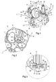
- the recess box 1 is intended to accommodate an electrical appliance embedded in a drywall.
- This body 2 has a side wall 3 of generally cylindrical shape, a bottom 4 and a front opening opposite the bottom 4.
- the wall 3 has an edge which defines the opening. This edge comprises a flange 5 which extends transversely to the side wall 3, projecting outwards.
- the flange 5 is thin and slightly protrudes from the side wall 3. In each of four locations evenly distributed angularly on the periphery of the flange 5, extends an ear 6 belonging to the edge.
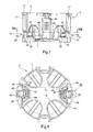
- Each lug 6 is substantially triangular and of the same thickness as the flange 5. It has two free edges of the same length and transverse relative to each other and a free end 9 forming a point away from the wall 3. The angle between the two edges at the end 9 is rounded.
- the ends 9 form the four corners of a square.
- the ears 6 are hidden behind the apparatus generally having a square base so that they occupy a maximum area.
- Each ear 6 has a root 13 towards the junction with the collar 5 and each lug 6 has a curvature at the root 13.
- the curvatures are such that the lugs 6 are oriented outwards and towards the bottom 4.
- the side wall 3 and the bottom 4 have knockouts 7 allowing, after removal of these knockouts 7, the establishment of incoming and outgoing conductors to connect to the electrical device.
- the knockouts 7 each comprise two substantially transverse portions relative to one another, one of the portions belonging to the bottom 4 of the box 1, while the other belongs to the side wall 3.
- Each knockout portion 7 is connected by a breakable zone 8 to the body 2, one of the breakable zones 8 connecting the knockout portion 7 to the side wall 3, the other breakable zone 8 connecting the knockout portion 7 to the bottom 4.
- the breakable zones 8 are plastic, the knockouts 7 and the body 2 being molded in one piece.
- the knockouts 7 and the cuts that accommodate them are here of generally oval shape.
- the angle between the side wall 3 and the bottom 4 at their connection is rounded so that the insertion of the box 1 in the partition is facilitated.
- the side wall 3 carries on its inner surface two extra thicknesses 10.
- Each overthickness 10 is thin and elongated, pierced with three holes side by side. These holes are intended to accommodate a mounting screw of the electrical device in the box 1. To the bottom 4, the holes pass through the wall 3 and open on the outside thereof because in this area, the wall 3 is formed only of the excess thickness 10.
- the two extra thicknesses 10 are positioned diametrically opposite.
- Each extra thickness 10 has on its inner surface to the box 1 small notches for fixing an electrical device.
- the wall 3 also has, on its outer surface, two recesses 11 diametrically opposed.
- the two recesses 11 and the two oversizes 10 are alternated and evenly distributed on the wall 3.
- each lug 6 is placed between an excess thickness 10 and a recess 11.
- This one is semi-cylindrical. It extends in an axial direction corresponding to the direction of the generatrices of the wall 3.
- the recess 11 extends from the flange 5 towards the bottom 4. Towards the bottom 4, the recess 11 opens out onto one of two windows 12 that the wall 3 has. On the side of the flange 5, this it ends with a ring whose inner radius is much smaller than that of the recess 11. The central opening of the ring allows the passage of the rod 15 of a screw 16. Au above this ring, the flange 5 is open on a small circular housing 17 to accommodate the head of the screw 16.
- This circular housing 17 comprises, substantially in the plane of the flange 5, a small projection forming a locking means 19 for the head of the screw 16.
- the window 12 has a substantially rectangular shape. Its height in the axial direction is much lower than the height of the recess 11.
- the window 12 is centered transversely to the axial direction on the rod 15 of the screw 16.
- a rectangular advance 18 of the wall 3 narrows the transverse dimension of the window on the side of the window 12 closest to the collar 5.
- the window 12 has an edge 20 on the side of the recess 11, an edge 21 opposite the edge 20, a rim 22 crenellated on the side of the advance 18 and an edge 23, right, opposite the edge 22.
- the edge 21 is at the distance from the plane comprising the bottom 4.
- the wall 3 has, along the edge 20, a flange 25 projecting.
- the flange 25 extends transversely to the wall 3 inward a distance equivalent to the radius of the recess 11.
- the rim 25 has a portion on each side of the recess 11. One of these portions is longer than the other since the edge 20 is not equal distance on either side of the recess 11 due to the advance 18.
- the bottom 4 has two semicircular steps 30, each extending in front of one of the windows 12.
- the peripheral edges of the steps 30 are opposite one another.
- Each step 30 reaches the height of the edge 21.
- the flat of the step 30 comprises two solid lateral zones and a central zone opening on a well 31. central extends from the window 12 to the peripheral edge.
- the well 31 extends in the axial direction from the edge 21 to the plane comprising the remainder of the bottom 4.
- the rod 15 of the screw 16 has a length substantially corresponding to the distance between the flange 5 and the bottom 4 so that when the head is snapped into its housing 17, the free end of the rod 15 is located in the well 31 without exceeding it.
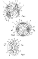
- the box 1 also comprises two clamping tabs 40 extending mainly parallel to the bottom 4.
- Each tab 40 comprises a plate 41 shaped angular sector, generally semi-cylindrical, slightly smaller than the step 30.
- the tabs 40 also comprise a boss 42 having a hub 43 at its center.
- the boss 42 extends in the axial direction over a length greater than the thickness of the plate 41.
- the plate 41 has a peripheral edge 44 and two aligned edges 45, 46 each extending from the boss 42 at one end of the edge 44.
- the edges 45, 46 are aligned on either side of the boss 42.
- the tab 40 has on one side a generally flat surface 47 having two recesses 49 on either side of a central zone.
- the central zone has three protruding ridges to better grip the inner surface of the partition.
- the plate 41 On the other side, in addition to the boss 42 projecting, the plate 41 has a wing 48 in the axial direction projecting from the same side of the boss 42.
- the wing 48 is positioned at the back of the central zone and extends from the boss 42 to the peripheral edge 44 of the plate 41.
- This wing 48 is here formed by a small U-shaped wall projecting from the plate 41 .
- the plate 41 On both sides of the wing 48 and in the center of the latter, the plate 41 has recesses. These three recesses extend to the back of the central area. On the back of the recesses 49, the surface of the tab 40 is flat.
- the various recesses allow in particular a saving of plastic material.
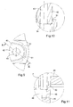
- the tab 40 is connected to the body 2 after molding by four breakable links plastic ( Figures 5, 10, 11).
- Two links 50 connect the rim 25 of the window 12 respectively to the edge 45 and the edge 46 of the tab 40.
- the surface 47 of the tab 40 is substantially in the plane having the edge 20.
- Two links 51 connect the free end boss 42 to the inner surface of the well 31, the boss 42 fitting slightly into the well 31. The severing of the links is specified below.
- Each hub 43 accommodates the rod 15 of the screw 16 so that the tab 40 is positioned at a determined height of the rod 15.
- the embedding box 1 Prior to the use of the tabs 40, the embedding box 1 is inserted into an opening of the partition 60.
- This partition 60 has an outer surface and an inner surface.
- the opening in the partition 60 is a circular opening whose diameter is such that during the depression of the box 1, the body 2 is pressed through this opening but the collar 5 and the lugs 6 remain on the side of the surface exterior.
- the contact between the outer surface and the projecting edge of the body 2 is then limited to contact with the ends 9 of the lugs 6.
- the flange 5 is slightly away from the plane of the front surface.
- the ears 6 are thin and curved, they are flexible. Each ear 6 has a pivotal freedom of a few degrees around its root 13.
- the tabs 40 when the tabs 40 come into contact with the inner surface of the partition 60, as is explained hereinafter, the tabs 40 are continued to be screwed so that the tightening amplifies not by the advance of the tabs. 40 but by the flattening of the ears 6 against the front surface. That is to say that the ears 6, which were curved towards the plane containing the bottom 4, are then flattened in the plane comprising the flange 5 ( Figure 15).
- the ears 6 perfectly fit the shape of the outer surface even if it has some irregularities.
- the user detects the sufficient clamping of the legs when he sees the ears 6 flattened on the partition 60, unlike the known boxes in which the operator is not informed. In these boxes, by continuing to tighten, the flange 5 and the ears 6 are raised and may prevent the apparatus, which it is desired to have in the box, to be properly pressed against the outer surface of the partition.
- the tab 40 is movable to pivot about the rod 15 between a retracted position in which it is positioned in the body 2 above the step 30 and an output position in which it has pivoted by a half-turn and is found outside the box 1. This pivoting is carried out with that of the screw 16 which also pivots, the tab 40 being, in these two positions, located at a given height of the rod 16.
- the tab 40 is also mobile in translation, mainly when it is outside the body 2. As can be seen in FIG. 5, the tab 40 can move to a higher position on the rod 15 at different positions. levels of the recess 11. In this case, the tab 40 is translated when the rod 15 pivots.
- the tab is connected to the body 2 by the two breakable links 51 (Figure 11) connecting the free end of the boss 42 with the wall Lateral of the well 31. These breakable links 51 are cut by simply pivoting the tab 30.
- the lug 40 is initially in the retracted position inside the box 1, with the screw 16 positioned in the recess 11 and passing through the hub 43 in order to be able to control the lug 40.
- This lug 40 is in its retracted position to the right of the window 12 and more particularly to the right of the portion comprising the advance 18.
- the head of the screw 16 being snapped into its housing with a screwdriver, when the screw 16 is rotated, the lug 30 and the screw 16 begin to pivot about the axis of the screw shank. .
- the links 51 break.
- the entire plate 41 is passed through the window 12.
- the lateral edge 46 abuts against the advance 18.
- the tab 40 can no longer pivot. Throughout this step, the tab 40 has remained at a constant height (in the axial direction).
- the tab 40 whose edge 46 is in abutment, is forced to mount along the rod 15 of the screw 16. Due to its initial position of the hub 43 (in the axis of the recess 11) it is in contact with the recess 11. By continuing to climb along the screw 15, the hub 43 remains in the recess 11 and the lateral edge 46 is located against a portion of the wall 3 near the recess 11. The edge 46 continues to abut against the wall 3 as long as the tightening of the screw 16 is continued.
- the tab 40 is in retracted position, the maneuver can stop. However, if we continue the rotation of the screw 16, the tab 40 being in abutment, it resumes its descent along the screw 16.
- this lug 40 is always in abutment against an element of the body 2 with the exception of the single height at which the passage through the window 12 is allowed.
- a plate in the form of an angular sector such as the plate 41, with a suitable radius, provides a tab 40 with the largest clamping surface. In the clamping position of the partition, the clamping forces on the inner surface are distributed over the large surface of the tab and the forces on the front surface are distributed over the four lugs 6, so that the risk of damaging the partition is limited.
- the ears have a first portion on the side of their root facing outwards and away from the bottom and a second portion facing outwards and toward the bottom so that they present a curved profile.
- the collar is discontinuous, even limited to the only locations of the ears.
Landscapes
- Engineering & Computer Science (AREA)
- Architecture (AREA)
- Civil Engineering (AREA)
- Structural Engineering (AREA)
- Connection Of Plates (AREA)
- Details Of Rigid Or Semi-Rigid Containers (AREA)
- Casings For Electric Apparatus (AREA)
- Connection Or Junction Boxes (AREA)
Applications Claiming Priority (1)
| Application Number | Priority Date | Filing Date | Title |
|---|---|---|---|
| FR0504681A FR2885745B1 (fr) | 2005-05-10 | 2005-05-10 | Boite d'encastrement et procede de fabrication |
Publications (3)
| Publication Number | Publication Date |
|---|---|
| EP1722453A2 true EP1722453A2 (de) | 2006-11-15 |
| EP1722453A3 EP1722453A3 (de) | 2010-11-10 |
| EP1722453B1 EP1722453B1 (de) | 2013-03-20 |
Family
ID=35448326
Family Applications (2)
| Application Number | Title | Priority Date | Filing Date |
|---|---|---|---|
| EP06290667.2A Expired - Lifetime EP1722472B1 (de) | 2005-05-10 | 2006-04-24 | Einbaudose und Herstellungsverfahren |
| EP20060290668 Expired - Lifetime EP1722453B1 (de) | 2005-05-10 | 2006-04-24 | Einbaudose |
Family Applications Before (1)
| Application Number | Title | Priority Date | Filing Date |
|---|---|---|---|
| EP06290667.2A Expired - Lifetime EP1722472B1 (de) | 2005-05-10 | 2006-04-24 | Einbaudose und Herstellungsverfahren |
Country Status (4)
| Country | Link |
|---|---|
| EP (2) | EP1722472B1 (de) |
| ES (2) | ES2550430T3 (de) |
| FR (1) | FR2885745B1 (de) |
| HU (1) | HUE026479T2 (de) |
Cited By (9)
| Publication number | Priority date | Publication date | Assignee | Title |
|---|---|---|---|---|
| AT504355B1 (de) * | 2006-12-18 | 2008-05-15 | Putz Georg | Mauer- bzw. wanddose für elektroarmaturen |
| GB2469515A (en) * | 2009-04-17 | 2010-10-20 | Demetri Kiloni | Electrical back box with flange |
| FR2963994A1 (fr) * | 2010-08-17 | 2012-02-24 | Cooper Technologies Co | Boitier pour cloison seche, a pattes de retenue rotatives et escamotables |
| FR2963995A1 (fr) * | 2010-08-17 | 2012-02-24 | Cooper Technologies Co | Boitier pour cloison seche, a logement de repli souple pour patte de retenue escamotable |
| ITBS20120053A1 (it) * | 2012-04-05 | 2013-10-06 | Ave Spa | Scatola elettrica da incasso per pareti leggere |
| ITMI20122021A1 (it) * | 2012-11-28 | 2014-05-29 | Gewiss Spa | Cassetta per l¿installazione ed il cablaggio di dispositivi elettrici, atta ad essere montata in modo incassato |
| WO2019068324A1 (de) | 2017-10-04 | 2019-04-11 | Oblamatik Ag | Montagehülse |
| WO2020016311A1 (de) * | 2018-07-18 | 2020-01-23 | Schneider Electric Industries Sas | Gehäuse |
| EP3540884B1 (de) | 2018-03-14 | 2021-11-24 | Kaiser GmbH & Co. KG | Installationsdose und einführöffnung für installationsdose |
Families Citing this family (4)
| Publication number | Priority date | Publication date | Assignee | Title |
|---|---|---|---|---|
| FR3011139B1 (fr) * | 2013-09-25 | 2017-05-26 | Legrand France | Boite electrique d'encastrement |
| EP3059816A1 (de) * | 2015-02-20 | 2016-08-24 | ABB Oy | Anbringungskasten |
| US11088518B2 (en) | 2017-10-06 | 2021-08-10 | Lutron Technology Company Llc | Mounting mechanism for an electrical device |
| US20260018874A1 (en) * | 2024-07-09 | 2026-01-15 | Abb Schweiz Ag | Old Work Box with Breakaway Wings |
Family Cites Families (7)
| Publication number | Priority date | Publication date | Assignee | Title |
|---|---|---|---|---|
| US2047294A (en) * | 1935-06-28 | 1936-07-14 | Joseph E Simek | Clamping device |
| US2875914A (en) * | 1956-10-31 | 1959-03-03 | Christopher C Buckels | Electrical outlet box |
| FR2670625B1 (fr) * | 1990-12-14 | 1996-08-02 | Merlin Gerin | Boite universelle d'encastrement pour appareillage electrique. |
| DE4241390C2 (de) * | 1992-12-09 | 1997-11-20 | Kaiser Gmbh & Co Kg | Elektrische Hohlwanddose, wie Schalterdose, Abzweigdose o. dgl. |
| FR2725318B1 (fr) * | 1994-10-04 | 1996-10-31 | Schneider Electric Sa | Boitier d'encastrement pour appareillage electrique |
| DE29622171U1 (de) * | 1996-12-20 | 1997-03-13 | Kaiser GmbH & Co KG, 58579 Schalksmühle | Elektrische Verbindungsdose, wie Schalterdose, Abzweigdose o.dgl. |
| FR2780567B1 (fr) * | 1998-06-29 | 2000-09-15 | Alombard Sa | Boite d'encastrement pour cloisons seches |
-
2005
- 2005-05-10 FR FR0504681A patent/FR2885745B1/fr not_active Expired - Fee Related
-
2006
- 2006-04-24 HU HUE06290667A patent/HUE026479T2/hu unknown
- 2006-04-24 EP EP06290667.2A patent/EP1722472B1/de not_active Expired - Lifetime
- 2006-04-24 ES ES06290667.2T patent/ES2550430T3/es not_active Expired - Lifetime
- 2006-04-24 EP EP20060290668 patent/EP1722453B1/de not_active Expired - Lifetime
- 2006-04-24 ES ES06290668T patent/ES2406941T3/es not_active Expired - Lifetime
Cited By (12)
| Publication number | Priority date | Publication date | Assignee | Title |
|---|---|---|---|---|
| AT504355B1 (de) * | 2006-12-18 | 2008-05-15 | Putz Georg | Mauer- bzw. wanddose für elektroarmaturen |
| GB2469515A (en) * | 2009-04-17 | 2010-10-20 | Demetri Kiloni | Electrical back box with flange |
| FR2963994A1 (fr) * | 2010-08-17 | 2012-02-24 | Cooper Technologies Co | Boitier pour cloison seche, a pattes de retenue rotatives et escamotables |
| FR2963995A1 (fr) * | 2010-08-17 | 2012-02-24 | Cooper Technologies Co | Boitier pour cloison seche, a logement de repli souple pour patte de retenue escamotable |
| ITBS20120053A1 (it) * | 2012-04-05 | 2013-10-06 | Ave Spa | Scatola elettrica da incasso per pareti leggere |
| ITMI20122021A1 (it) * | 2012-11-28 | 2014-05-29 | Gewiss Spa | Cassetta per l¿installazione ed il cablaggio di dispositivi elettrici, atta ad essere montata in modo incassato |
| EP2738896A1 (de) | 2012-11-28 | 2014-06-04 | GEWISS S.p.A. | Box zur Installation und Verdrahtung elektrischer Geräte, die zum Einbetten angepasst sind |
| WO2019068324A1 (de) | 2017-10-04 | 2019-04-11 | Oblamatik Ag | Montagehülse |
| US11705705B2 (en) | 2017-10-04 | 2023-07-18 | Oblamatik Ag | Mounting sleeve |
| EP3540884B1 (de) | 2018-03-14 | 2021-11-24 | Kaiser GmbH & Co. KG | Installationsdose und einführöffnung für installationsdose |
| EP3540884B2 (de) † | 2018-03-14 | 2025-10-15 | Kaiser GmbH & Co. KG | Installationsdose und einführöffnung für installationsdose |
| WO2020016311A1 (de) * | 2018-07-18 | 2020-01-23 | Schneider Electric Industries Sas | Gehäuse |
Also Published As
| Publication number | Publication date |
|---|---|
| ES2550430T3 (es) | 2015-11-06 |
| EP1722453B1 (de) | 2013-03-20 |
| EP1722472A3 (de) | 2010-08-11 |
| EP1722472A2 (de) | 2006-11-15 |
| FR2885745B1 (fr) | 2007-08-10 |
| FR2885745A1 (fr) | 2006-11-17 |
| HUE026479T2 (hu) | 2016-06-28 |
| ES2406941T3 (es) | 2013-06-10 |
| EP1722472B1 (de) | 2015-07-29 |
| EP1722453A3 (de) | 2010-11-10 |
Similar Documents
| Publication | Publication Date | Title |
|---|---|---|
| EP1722453B1 (de) | Einbaudose | |
| EP3435812B1 (de) | Behälter zur verwendung für lebensmittel | |
| EP2068408B1 (de) | Winkelelement für Ablaufrinnen | |
| EP0053543A2 (de) | Anordnungen zum Befestigen von Gegenständen an Blechen, welche nur von einer Seite her zugänglich sind | |
| EP2068409B1 (de) | Winkelelement für Ablaufrinnen mit Schwenkklappen | |
| EP2966741B1 (de) | Installationshalterung für Einbaudose und elektrische Geräte mit einer solchen Halterung | |
| CA2515573A1 (fr) | Dispositif de fixation a pince | |
| EP4060840B1 (de) | Elektrisches einbaugerät | |
| EP2112734B1 (de) | Elektrogerät zum Aufsetzen auf ein Einbaugehäuse | |
| EP2431641B1 (de) | Befestigungsvorrichtung für einen Anschluss eines fluidführenden Rohres an einer Hohlwand | |
| FR2796367A1 (fr) | Obturateur pour une ouverture realisee dans une tole | |
| EP1775814B1 (de) | Einbaudose mit Spannschraubtriebführung | |
| EP1775815B1 (de) | Einbaudose mit optimierter Befestigung | |
| EP3115515B1 (de) | Schachtabdeckung mit einem rahmen und einem paneel | |
| EP3822427B1 (de) | Abstandshalterzubehör für die aufdoppelung einer wand | |
| FR2972860A1 (fr) | Dispositif de connexion electrique pour mise a la terre de structures metalliques | |
| FR2883340A1 (fr) | Dispositif de fixation d'un anneau d'arrimage sur un element porteur et support le comportant | |
| EP3222172A1 (de) | Anlage für pflanze, die eine befestigungsvorrichtung und einen behälter umfasst | |
| WO2026052919A1 (fr) | Système d'étalement d'un cordon de pâte le long d'une paroi interne d'une chambre cylindrique | |
| FR3116455A1 (fr) | Dispositif coupe-tube | |
| FR2866083A1 (fr) | Dispositif de fixation par encliquetage de deux elements et boitier le comportant | |
| EP2578782A1 (de) | Elektrischer Kasten | |
| EP3506443A1 (de) | Elektrische anschlussdose mit variabler tiefe | |
| FR2766025A1 (fr) | Boitier d'appareillage electrique pour cloison seche | |
| FR2848622A1 (fr) | Procede de fixation etanche d'un panneau sur un element de carrosserie d'un vehicule et dispositif correspondant |
Legal Events
| Date | Code | Title | Description |
|---|---|---|---|
| PUAI | Public reference made under article 153(3) epc to a published international application that has entered the european phase |
Free format text: ORIGINAL CODE: 0009012 |
|
| AK | Designated contracting states |
Kind code of ref document: A2 Designated state(s): AT BE BG CH CY CZ DE DK EE ES FI FR GB GR HU IE IS IT LI LT LU LV MC NL PL PT RO SE SI SK TR |
|
| AX | Request for extension of the european patent |
Extension state: AL BA HR MK YU |
|
| PUAL | Search report despatched |
Free format text: ORIGINAL CODE: 0009013 |
|
| AK | Designated contracting states |
Kind code of ref document: A3 Designated state(s): AT BE BG CH CY CZ DE DK EE ES FI FR GB GR HU IE IS IT LI LT LU LV MC NL PL PT RO SE SI SK TR |
|
| AX | Request for extension of the european patent |
Extension state: AL BA HR MK YU |
|
| 17P | Request for examination filed |
Effective date: 20110202 |
|
| AKX | Designation fees paid |
Designated state(s): AT BE BG CH CY CZ DE DK EE ES FI FR GB GR HU IE IS IT LI LT LU LV MC NL PL PT RO SE SI SK TR |
|
| GRAP | Despatch of communication of intention to grant a patent |
Free format text: ORIGINAL CODE: EPIDOSNIGR1 |
|
| GRAS | Grant fee paid |
Free format text: ORIGINAL CODE: EPIDOSNIGR3 |
|
| GRAA | (expected) grant |
Free format text: ORIGINAL CODE: 0009210 |
|
| AK | Designated contracting states |
Kind code of ref document: B1 Designated state(s): AT BE BG CH CY CZ DE DK EE ES FI FR GB GR HU IE IS IT LI LT LU LV MC NL PL PT RO SE SI SK TR |
|
| REG | Reference to a national code |
Ref country code: GB Ref legal event code: FG4D Free format text: NOT ENGLISH |
|
| REG | Reference to a national code |
Ref country code: CH Ref legal event code: EP |
|
| REG | Reference to a national code |
Ref country code: IE Ref legal event code: FG4D Free format text: LANGUAGE OF EP DOCUMENT: FRENCH |
|
| REG | Reference to a national code |
Ref country code: AT Ref legal event code: REF Ref document number: 602580 Country of ref document: AT Kind code of ref document: T Effective date: 20130415 |
|
| REG | Reference to a national code |
Ref country code: DE Ref legal event code: R096 Ref document number: 602006035156 Country of ref document: DE Effective date: 20130516 |
|
| REG | Reference to a national code |
Ref country code: ES Ref legal event code: FG2A Ref document number: 2406941 Country of ref document: ES Kind code of ref document: T3 Effective date: 20130610 |
|
| PG25 | Lapsed in a contracting state [announced via postgrant information from national office to epo] |
Ref country code: LT Free format text: LAPSE BECAUSE OF FAILURE TO SUBMIT A TRANSLATION OF THE DESCRIPTION OR TO PAY THE FEE WITHIN THE PRESCRIBED TIME-LIMIT Effective date: 20130320 Ref country code: BG Free format text: LAPSE BECAUSE OF FAILURE TO SUBMIT A TRANSLATION OF THE DESCRIPTION OR TO PAY THE FEE WITHIN THE PRESCRIBED TIME-LIMIT Effective date: 20130620 Ref country code: SE Free format text: LAPSE BECAUSE OF FAILURE TO SUBMIT A TRANSLATION OF THE DESCRIPTION OR TO PAY THE FEE WITHIN THE PRESCRIBED TIME-LIMIT Effective date: 20130320 |
|
| PGFP | Annual fee paid to national office [announced via postgrant information from national office to epo] |
Ref country code: DE Payment date: 20130529 Year of fee payment: 8 |
|
| REG | Reference to a national code |
Ref country code: AT Ref legal event code: MK05 Ref document number: 602580 Country of ref document: AT Kind code of ref document: T Effective date: 20130320 |
|
| REG | Reference to a national code |
Ref country code: LT Ref legal event code: MG4D |
|
| PG25 | Lapsed in a contracting state [announced via postgrant information from national office to epo] |
Ref country code: FI Free format text: LAPSE BECAUSE OF FAILURE TO SUBMIT A TRANSLATION OF THE DESCRIPTION OR TO PAY THE FEE WITHIN THE PRESCRIBED TIME-LIMIT Effective date: 20130320 Ref country code: GR Free format text: LAPSE BECAUSE OF FAILURE TO SUBMIT A TRANSLATION OF THE DESCRIPTION OR TO PAY THE FEE WITHIN THE PRESCRIBED TIME-LIMIT Effective date: 20130621 Ref country code: LV Free format text: LAPSE BECAUSE OF FAILURE TO SUBMIT A TRANSLATION OF THE DESCRIPTION OR TO PAY THE FEE WITHIN THE PRESCRIBED TIME-LIMIT Effective date: 20130320 Ref country code: SI Free format text: LAPSE BECAUSE OF FAILURE TO SUBMIT A TRANSLATION OF THE DESCRIPTION OR TO PAY THE FEE WITHIN THE PRESCRIBED TIME-LIMIT Effective date: 20130320 |
|
| REG | Reference to a national code |
Ref country code: NL Ref legal event code: VDEP Effective date: 20130320 |
|
| PG25 | Lapsed in a contracting state [announced via postgrant information from national office to epo] |
Ref country code: SK Free format text: LAPSE BECAUSE OF FAILURE TO SUBMIT A TRANSLATION OF THE DESCRIPTION OR TO PAY THE FEE WITHIN THE PRESCRIBED TIME-LIMIT Effective date: 20130320 Ref country code: CZ Free format text: LAPSE BECAUSE OF FAILURE TO SUBMIT A TRANSLATION OF THE DESCRIPTION OR TO PAY THE FEE WITHIN THE PRESCRIBED TIME-LIMIT Effective date: 20130320 Ref country code: EE Free format text: LAPSE BECAUSE OF FAILURE TO SUBMIT A TRANSLATION OF THE DESCRIPTION OR TO PAY THE FEE WITHIN THE PRESCRIBED TIME-LIMIT Effective date: 20130320 Ref country code: NL Free format text: LAPSE BECAUSE OF FAILURE TO SUBMIT A TRANSLATION OF THE DESCRIPTION OR TO PAY THE FEE WITHIN THE PRESCRIBED TIME-LIMIT Effective date: 20130320 Ref country code: AT Free format text: LAPSE BECAUSE OF FAILURE TO SUBMIT A TRANSLATION OF THE DESCRIPTION OR TO PAY THE FEE WITHIN THE PRESCRIBED TIME-LIMIT Effective date: 20130320 Ref country code: PT Free format text: LAPSE BECAUSE OF FAILURE TO SUBMIT A TRANSLATION OF THE DESCRIPTION OR TO PAY THE FEE WITHIN THE PRESCRIBED TIME-LIMIT Effective date: 20130722 Ref country code: RO Free format text: LAPSE BECAUSE OF FAILURE TO SUBMIT A TRANSLATION OF THE DESCRIPTION OR TO PAY THE FEE WITHIN THE PRESCRIBED TIME-LIMIT Effective date: 20130320 Ref country code: IS Free format text: LAPSE BECAUSE OF FAILURE TO SUBMIT A TRANSLATION OF THE DESCRIPTION OR TO PAY THE FEE WITHIN THE PRESCRIBED TIME-LIMIT Effective date: 20130720 |
|
| PG25 | Lapsed in a contracting state [announced via postgrant information from national office to epo] |
Ref country code: PL Free format text: LAPSE BECAUSE OF FAILURE TO SUBMIT A TRANSLATION OF THE DESCRIPTION OR TO PAY THE FEE WITHIN THE PRESCRIBED TIME-LIMIT Effective date: 20130320 Ref country code: CY Free format text: LAPSE BECAUSE OF FAILURE TO SUBMIT A TRANSLATION OF THE DESCRIPTION OR TO PAY THE FEE WITHIN THE PRESCRIBED TIME-LIMIT Effective date: 20130320 |
|
| REG | Reference to a national code |
Ref country code: CH Ref legal event code: PL |
|
| PG25 | Lapsed in a contracting state [announced via postgrant information from national office to epo] |
Ref country code: MC Free format text: LAPSE BECAUSE OF FAILURE TO SUBMIT A TRANSLATION OF THE DESCRIPTION OR TO PAY THE FEE WITHIN THE PRESCRIBED TIME-LIMIT Effective date: 20130320 |
|
| PLBE | No opposition filed within time limit |
Free format text: ORIGINAL CODE: 0009261 |
|
| STAA | Information on the status of an ep patent application or granted ep patent |
Free format text: STATUS: NO OPPOSITION FILED WITHIN TIME LIMIT |
|
| REG | Reference to a national code |
Ref country code: IE Ref legal event code: MM4A |
|
| PG25 | Lapsed in a contracting state [announced via postgrant information from national office to epo] |
Ref country code: DK Free format text: LAPSE BECAUSE OF FAILURE TO SUBMIT A TRANSLATION OF THE DESCRIPTION OR TO PAY THE FEE WITHIN THE PRESCRIBED TIME-LIMIT Effective date: 20130320 Ref country code: CH Free format text: LAPSE BECAUSE OF NON-PAYMENT OF DUE FEES Effective date: 20130430 Ref country code: LI Free format text: LAPSE BECAUSE OF NON-PAYMENT OF DUE FEES Effective date: 20130430 |
|
| 26N | No opposition filed |
Effective date: 20140102 |
|
| GBPC | Gb: european patent ceased through non-payment of renewal fee |
Effective date: 20130620 |
|
| REG | Reference to a national code |
Ref country code: DE Ref legal event code: R097 Ref document number: 602006035156 Country of ref document: DE Effective date: 20140102 |
|
| PG25 | Lapsed in a contracting state [announced via postgrant information from national office to epo] |
Ref country code: IE Free format text: LAPSE BECAUSE OF NON-PAYMENT OF DUE FEES Effective date: 20130424 Ref country code: GB Free format text: LAPSE BECAUSE OF NON-PAYMENT OF DUE FEES Effective date: 20130620 |
|
| REG | Reference to a national code |
Ref country code: DE Ref legal event code: R119 Ref document number: 602006035156 Country of ref document: DE |
|
| REG | Reference to a national code |
Ref country code: DE Ref legal event code: R119 Ref document number: 602006035156 Country of ref document: DE Effective date: 20141101 |
|
| PG25 | Lapsed in a contracting state [announced via postgrant information from national office to epo] |
Ref country code: DE Free format text: LAPSE BECAUSE OF NON-PAYMENT OF DUE FEES Effective date: 20141101 |
|
| PG25 | Lapsed in a contracting state [announced via postgrant information from national office to epo] |
Ref country code: TR Free format text: LAPSE BECAUSE OF FAILURE TO SUBMIT A TRANSLATION OF THE DESCRIPTION OR TO PAY THE FEE WITHIN THE PRESCRIBED TIME-LIMIT Effective date: 20130320 |
|
| PG25 | Lapsed in a contracting state [announced via postgrant information from national office to epo] |
Ref country code: LU Free format text: LAPSE BECAUSE OF NON-PAYMENT OF DUE FEES Effective date: 20130424 Ref country code: HU Free format text: LAPSE BECAUSE OF FAILURE TO SUBMIT A TRANSLATION OF THE DESCRIPTION OR TO PAY THE FEE WITHIN THE PRESCRIBED TIME-LIMIT; INVALID AB INITIO Effective date: 20060424 |
|
| REG | Reference to a national code |
Ref country code: FR Ref legal event code: PLFP Year of fee payment: 11 |
|
| PGFP | Annual fee paid to national office [announced via postgrant information from national office to epo] |
Ref country code: ES Payment date: 20160504 Year of fee payment: 11 |
|
| PGFP | Annual fee paid to national office [announced via postgrant information from national office to epo] |
Ref country code: IT Payment date: 20160411 Year of fee payment: 11 Ref country code: BE Payment date: 20160421 Year of fee payment: 11 |
|
| REG | Reference to a national code |
Ref country code: FR Ref legal event code: PLFP Year of fee payment: 12 |
|
| REG | Reference to a national code |
Ref country code: BE Ref legal event code: MM Effective date: 20170430 |
|
| REG | Reference to a national code |
Ref country code: FR Ref legal event code: PLFP Year of fee payment: 13 |
|
| PG25 | Lapsed in a contracting state [announced via postgrant information from national office to epo] |
Ref country code: BE Free format text: LAPSE BECAUSE OF NON-PAYMENT OF DUE FEES Effective date: 20170430 Ref country code: IT Free format text: LAPSE BECAUSE OF NON-PAYMENT OF DUE FEES Effective date: 20170424 |
|
| REG | Reference to a national code |
Ref country code: ES Ref legal event code: FD2A Effective date: 20180705 |
|
| PG25 | Lapsed in a contracting state [announced via postgrant information from national office to epo] |
Ref country code: ES Free format text: LAPSE BECAUSE OF NON-PAYMENT OF DUE FEES Effective date: 20170425 |
|
| PGFP | Annual fee paid to national office [announced via postgrant information from national office to epo] |
Ref country code: FR Payment date: 20200316 Year of fee payment: 15 |
|
| PG25 | Lapsed in a contracting state [announced via postgrant information from national office to epo] |
Ref country code: FR Free format text: LAPSE BECAUSE OF NON-PAYMENT OF DUE FEES Effective date: 20210430 |