EP1722465A2 - Système de bobinage de d'insertion d'enroulements dans des composants de machines électrodynamiques - Google Patents
Système de bobinage de d'insertion d'enroulements dans des composants de machines électrodynamiques Download PDFInfo
- Publication number
- EP1722465A2 EP1722465A2 EP06009212A EP06009212A EP1722465A2 EP 1722465 A2 EP1722465 A2 EP 1722465A2 EP 06009212 A EP06009212 A EP 06009212A EP 06009212 A EP06009212 A EP 06009212A EP 1722465 A2 EP1722465 A2 EP 1722465A2
- Authority
- EP
- European Patent Office
- Prior art keywords
- platform
- support member
- application tool
- coils
- stations
- Prior art date
- Legal status (The legal status is an assumption and is not a legal conclusion. Google has not performed a legal analysis and makes no representation as to the accuracy of the status listed.)
- Granted
Links
Images




Classifications
-
- H—ELECTRICITY
- H02—GENERATION; CONVERSION OR DISTRIBUTION OF ELECTRIC POWER
- H02K—DYNAMO-ELECTRIC MACHINES
- H02K15/00—Processes or apparatus specially adapted for manufacturing, assembling, maintaining or repairing of dynamo-electric machines
- H02K15/06—Embedding prefabricated windings in the machines
- H02K15/062—Windings in slots; Salient pole windings
- H02K15/065—Windings consisting of complete sections, e.g. coils or waves
- H02K15/067—Windings consisting of complete sections, e.g. coils or waves inserted in parallel to the axis of the slots or inter-polar channels
- H02K15/068—Strippers; Embedding windings by strippers
-
- H—ELECTRICITY
- H02—GENERATION; CONVERSION OR DISTRIBUTION OF ELECTRIC POWER
- H02K—DYNAMO-ELECTRIC MACHINES
- H02K15/00—Processes or apparatus specially adapted for manufacturing, assembling, maintaining or repairing of dynamo-electric machines
- H02K15/04—Processes or apparatus specially adapted for manufacturing, assembling, maintaining or repairing of dynamo-electric machines of windings prior to their mounting into the machines
- H02K15/043—Processes or apparatus specially adapted for manufacturing, assembling, maintaining or repairing of dynamo-electric machines of windings prior to their mounting into the machines winding flat conductive wires or sheets
Definitions
- the present invention relates to solutions for manufacturing wound components of dynamo-electric machines, for example stator cores having coils wound with an electric conductor, such as a copper wire or a copper bar conductor.
- the present invention concerns optimization of manufacturing having operations like winding to form the coils which are external of the stator core, and successive insertion of the same coils into the stator core.
- the coils are wound and placed on an insertion tool in predetermined positions.
- the insertion tool successively guides the coils into the stator core during the insertion operation.
- the insertion tool usually has a series of guide posts around which the coils are positioned as a result of the winding operation.
- the guide posts guide the coils as they are being pushed to become inserted within slots of the stator core that has previously been aligned with the guide posts.
- a transfer system which is typically a pallet conveyor system or a rotating table solution.
- a problem in the manufacturing systems can be that there is inaccuracy in keeping the position of the coils on the insertion tool during the transfer stages of the latter, and that this ultimately produces incorrect positioning of the coils within the dynamo-electric component as a result of the insertion operations.
- transfer movements or positioning movements of the insertion tool when the latter is carrying the coils is an essential operational aspect of systems functioning according to the winding and insertion principles. It is crucial for manufacturing quality and avoiding malfunctions of these systems that the coils be located with accuracy on the insertion tool, and in particular that this accuracy be maintained on the insertion tool constantly and until the coils have been successfully inserted within the dynamo-electric component. Therefore, transferring and positioning of the insertion tool that is loaded with coils should occur accurately and without disturbing the conditions of the coils, as they have been produced by the winding operations.
- the amount of time required for accomplishing the transfer movements or the positioning movements of the insertion tool is particularly important for the manufacturing time of the system, therefore the time required for accomplishing transfer and positioning of the insertion tool needs to be optimized in order to improve the production amounts of dynamo-electric components that can be obtained from the manufacturing system.
- the travel routes which the insertion tool needs to accomplish between the various station by the transfer solution influences the disposition of the stations, therefore the layout of machinery on the available floor space of the manufacturing site.
- the transfer solution has a platform with at least a support member for supporting the insertion tools so that the latter can be brought to, or taken away from, the stations
- the platform can become clear of the application tool by relative movement between the platform and the application tool in a direction that is different from the direction for supporting the application tool on the support member.
- Figure 1 shows a manufacturing system having at least a winding station 10 and an insertion station 11 in which a stator core 12 is processed by completing it with coils 13 (see also figure 1a) inserted in slots 12'.
- coils 13 are produced and placed on insertion tool 14, which is successively transferred to insertion station 11 by transfer solution 18 comprising a moveable platform assembly.
- the insertion tool 14 is represented schematic and transparent, positioned at insertion station 11.
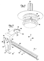
- Insertion tool 14 is provided with insertion rods 15 (see for example figures 4 and 8), which guide the coils during the insertion operation that occurs at station 11.
- Stator cores 12 that need to receive the coils arrive at the insertion station by traveling with transfer solution 18. Finished stator cores 12 that have already received the coils at the insertion station depart by traveling with the same transfer solution 18.
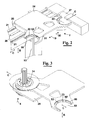
- Figures 2 and 3 show details of an embodiment of the transfer solution 18. More particularly, the transfer solution foresees two moveable support portions 22 and 23, each for supporting an insertion tool.
- the support portions are both on one side of a platform plate 24, which is bolted to a slide base 25.
- the slide base can translate in directions 19 and 20 by being guided on rail members 21.
- the translation motions in directions 19 and 20 are imparted to slide base 25 by means of a drive belt 26.
- Drive belt 26 is connected to slide base 25 and can extend aside the length of rail members 21.
- Drive belt 26 can be moved in directions 19 and 20 by motor gear unit 27 which ultimately pulls slide base 25 to translate it in either of directions 19 and 20 .
- Each of support portions 22 and 23 of platform plate 24 can support an insertion tool like 14 (see also figure 4).
- insertion tool 14 is shown partially transparent and supported by support portion 22. The transparency is for showing a support member 29 of a load device 28 foreseen at winding station 10.
- support portion 22 can be destined to support empty insertion tools, i.e. insertion tools that are returning to winding station 10 after having used them to insert coils in the stator core at insertion station 11.
- This transfer scenario can be like the situation shown in figure 3.
- support portion 23 can be destined to support insertion tools replenished with coils, i.e. that are carrying coils to insertion station 11, which can be like the situation shown in figure 1 at the insertion station.
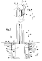
- each of support portions 22 and 23 can be configured to have a seat 50, which can be of annular cylindrical configuration having an entrance incline 51 (see also figure 7).
- Seat 50 is sized to receive a rim portion 42 of insertions tool 14. The rim portion 42 bears and engages on bottom 50' of seat 50 so that the insertion tool results supported by platform plate 24 in direction B.
- Incline 51 assists entrance of rim portion 42 inside seat 50.
- Seat 50 can have a pin 52 which can be received in a recess of the insertion tool so as to maintain by engagement the orientation of the insertion tool within seat 50.
- Seat 50 is open in portion 53, i.e. on one side of seat 50 to allow removal or receiving of the insertion tool in direction C.
- support portions 22 and 23 can become clear of the insertion tool 14 by relative movement of platform plate 24 in directions C, which are parallel to directions 19 and 20, for situations that are more fully described in the following.
- platform plate 24 which is carrying an empty insertion tool (like is shown in figure 3) can be moved by translation in direction 19 to be positioned at winding station 10, where the same insertion tool can be replenished with coils.
- support portion 22 with the empty insertion tool can be aligned with support member 29 of load device 28 (shown in figures 1, 3, 5 and 7).
- the alignment is achieved by stopping translation of platform plate 24 (shown with phantom line representation in figure 1) at location 10', to achieve alignment of support portion 22 with support member 29 of load device 28.
- insertion tool has been removed from the position of support portion 22.
- load device 28, by using support member 29, can remove the empty insertion tool from support portion 22 and reload support portion 23 with an insertion tool having coils 13 (an insertion tool loaded with coils at the insertion station is shown in figure 8).
- Support member 29 of load device 28 has a support portion 30, which has a seat configuration and opening very similar to seats 50 and openings 53 of support portions 22 and 23, respectively, for supporting the insertion tools in direction like B and for receiving and removing the insertion tools in direction like C'.
- Support member 29 loads an insertion tool onto itself by receiving rim portion like 41 of the insertion tools - (see also figures 3, 5, and 7, and particularly figures 3, and 7, where support member 29 is aligned with the insertion tool in a superimposed manner and ready for receiving the rim portion like 41 in its support portion 30 having seat like 50)
- Support member 29 of load device 28 is capable of translating in direction 31 and 32 by being assembled on carriage 33 which can translate on guides 33'. Translations in directions 31 and 32 are practically perpendicular to the general transfer direction A of the manufacturing system occurring along guides 21. Support member 29 can also translate in vertical directions 34 and 35 (see figure 5), i.e. respectively into and out of the page of figure 1, due to its direct assembled on guides 36, which are moveable in bushes 36' of carriage 33.
- Linear drive 37 which is carried by carriage 33 can be used to drive the translation in directions 34 and 35 of guides 36 for obtaining translations in directions 34 and 35 of member 29, whilst drive 38 can be used to drive the translation in directions 31 ad 32 of carriage 33 for obtaining translations in directions 32 and 31 of member 29.
- Figure 3 and 7 show the empty insertion tool, i.e. without coils, as it can be aligned at the winding station, and being supported by portion 22 of platform plate 24 by having rim 42 in seat 50 of portion 22. Furthermore, support member 29 is shown aligned with the insertion tool after having accomplished translation in direction 31 with respect to the position of figures 1 and 5 and by having consequently passed portion 40 of insertion tool 14 through opening 53 of portion 30 of support member 29. Support member 29 is now ready to remove the empty insertion tool from support portion 22. Successively, support member 29 can be raised in direction 35 to come into contact with the underside of rim 41 in order to support insertion tool 14 in the vertical direction like B (see fig. 7).
- support member 29 moves in direction 35 to bring rim 41 inside seat like 50 of support member 29 and into contact with bottom 50' of seat 50.
- Support arm 29 continues by being moved in vertical direction 35 to lift rim 42 in the vertical direction like B thereby bringing rim 42 out of seat like 50 of support portion 22 and at the same time achieving that smaller diameter portion 44 of insertion tool 14 becomes aligned with the open portion like 53 of seat like 50 of support portion 22 to allow support portion 22 to move in directions 20 or C for causing support portion 22 to become clear of insertion tool 14, therefore to clear the insertions tool in directions like 20 or C with respect to platform plate 24.
- support member 29 may having a further movement assembly for causing it to move in directions opposite to 20 or C, when it is supporting insertion tool 14 like has been described above, to achieve that support portion 22 becomes clear of insertion tool 14.
- support member 29 of the load device can be moved in direction 32 to bring the insertion tool into alignment with a cylindrical seat 10" (see figure 1) of the winding position.
- support member 29 can be moved downwards in direction 34 to deposit the insertion tool in the cylindrical seat 10" of the winding position.
- rims 41, 42, 43 can be configured like portions of flange structures (see figure 7)and together with portion 44 and 40 can be portions of cylindrical member 45, which is an assembled part that forms insertion tool 14 (see also figure 4 and 8). Furthermore, cylindrical member 45 is moveable in vertical directions 34 and 35 with respect to central member 47 by mounting cylindrical member 45 so that it can slide on collar member 48. Collar member 48 is fixed to central member 47. Collar member 48 supports insertion rods 15. Springs 49 assembled between collar member 48 and cylindrical member 45 are preloaded to normally push cylindrical member 45 in direction 34, i.e. downwards.
- Portion 46 of cylindrical member 45 can be received for example in the cylindrical seat 10" of the winding station and in a similar seat 70 of the insertion station (see figure 8 for the cylindrical seat of the insertion station).
- Ball 46' can enter and engage within corresponding recesses (not shown) of the cylindrical seats for locking the insertion tool therein.
- End 45' of cylindrical member 45 can engage ball 46' to maintain ball 46' engaged within the recesses.
- Springs 49, when pushing cylindrical member 45 in direction 35 cause end 45' to push on ball 46' to maintain it engaged within the recesses.
- member 45 will be moved downwards with respect to central member 47 by springs 49 so that end 45' engages ball 46' to force it into engagement in an aligned recess of the cylindrical seats. This will stop any further movement of cylindrical member 45, and will thus allow rim 41 to move out of a support portion like 30 of support member 29. This is also due to an extra descent in direction 34 accomplished by support member 29 when cylindrical member 45 has become stationary.
- support member 29 can move clear of the insertion tool by translating in direction 32 or C', which causes portion 44 of the insertion tool to pass though open side 53 of support portion 30 belonging to support member 29.
- support member 29 can reload the same insertion tool back onto platform plate 24 by accomplishing in a reverse sequence the operations that have been described in the foregoing.
- a sequence of operations for exchanging insertion tools between the winding station and platform plate 24, can foresee that before removing an empty tool present on the support base in support portion 22, a replenished tool is loaded in support portion 23 by first aligning support portion 23 with support member 29 at the winding station. Once the replenished tool has been loaded in support portion 23, the empty insertion tool can be removed from support portion 22 in the manner that has been described in the foregoing.
- Figure 1 can be showing a replenished insertion tool in support portion 23 and aligned at the insertion station 11, after having been transferred from the winding station by moving support plate in direction 20.
- support portion 23 is aligned with lifting rods 61 of load device 60, which is typically located at the insertion station 11 (see also figures 6 and 8).
- Lifting rods 61 are upright extensions fixed to plate 62 which can be moved in directions 34 and 35 by actuator 63.
- platform assembly 18 can be moved in direction 19 in order to cause support portion 23 to become clear of insertion tool 14 by passing narrow portion 44 through opening 53.
- lifting rods 61 can be lowered in direction 34 to place the insertion tool 14 in an aligned cylindrical seat 70 of slide member 71 (see this condition in figure 8).
- Bores like 72 are present in cylindrical seat 70 for allowing passage of lifting rods 61 through cylindrical seat 70.
- slide member 71 can be translated in direction 32 to align the insertion tool in the insertion position where the coils become inserted in the slots of the stator core.
- An opposite sequence of operations on behalf of slide member 71 and lifting rods 61 can be performed involving movements in directions 31 and 35 to remove the empty insertion tool from the insertion station and reload it in a portion 22 of platform plate 24 by passing narrow portion 44 through opening 53.
- Figure 9 shows a manufacturing system having four winding stations 90, 91, 92, 93 (like winding station 10 of figure 1) located on one side of transfer solution 94.
- An insertion station 95 (like insertion station 11 of figure 1) can be foreseen between the winding stations and on the other side of transfer solution 94.
- Empty and replenished insertion tools 14 can be transferred between the winding station and the insertion station by means of moveable platform plates 97 and 98. More precisely, platform plate 97 transfers insertions tools between winding stations 90, 91 and insertion station 95, whilst platform plate 98 transfers insertion tools between winding stations 92, 93 and insertion station 95.
- This configuration of the manufacturing system can achieve a higher production of the dynamoelectric components due to the presence of multiple platform plates 97 and 98 for transferring the insertion tools while the multiple winding stations that can be working in parallel. Only one insertion station has been shown in the assumption that it is capable of processing the output of the four winding stations and that platform plates 97 and 98 can be employed in receiving, removing or transferring insertions tools simultaneously, i.e. operating in parallel and synchronized or unsynchronized with respect to each other.
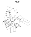
- FIG 10 shows more in detail that platform plate 97 or 98 can have two support portions 99, 100 which are similar to support portions 22 and 23 described in the foregoing.
- support portions 99, 100 are on opposite sides of the platform plate with openings 53 facing opposite directions.
- Platform plates 97 and 98 can be mounted on respective slide bases like slide base 25 of the foregoing, although with the difference that platform plates 97 and 98 are rotatably mounted on the slide bases like 25 - i.e. capable of rotation R around respective axes 101' of respective axles (hidden by gears 103). More particularly, each of the axles is integral with the respective platform plates 97 and 98 and is mounted to rotate on the respective slide base like 25 that is below.
- Gears 103 are integral with the heads of the axles or bolted to support plates 97 and 98 (as shown in figure 10), so that rotations R can be imparted by drive gears 104.
- Drive gears 104 are driven by respective motor units 105.
- Drive gears 104 and motor units 105 can be present at the stations to engage gears 103 if rotations R are required.
- Drive gears 104 can translate in directions 34 and 35, respectively to engage and disengage gears 103.
- Support plates 97 and 98 can be locked to the slide bases like 25 to avoid any unwanted rotations R around axes 101'.
- a releasable locking pin 109 can be foreseen on the slide bases like 25 for engaging aligned recesses of the support plates 97 and 98 when locking to avoid rotations R is required.
- the recess is removed due to the cut out made in plate 97 to show the end 109' of pin 109.
- the locking action of pin 109 can be released by a fork type actuating device 110 (shown partially in figure 10), which can translate in directions 34 and 35 to be able to engage and disengage head 109" of pin 109. Therefore, actuating device 110 can be present at the stations to cause the locking and unlocking actions of pin 109 depending on whether rotations of the support plates are required.
- the locking action of pin 109 is required when the support plates are moved between the stations.
- Rotation R of the support plates can be for 180° around axes 101' in order to exchange position of support portions 99 and 100. Consequently, and as an example, support portion 100 can be destined for carrying empty support portions to the winding stations, whilst support portion 99 can be destined for carrying replenished insertion tools from the winding stations to the insertion station. At the winding station, or at the insertion station, the support plates can be rotated to exchange the position of the support portions 99 and 100 to follow sequences of loading the insertion tools, which are similar to those described in the foregoing for figure 1 with reference to support portions 22 and 23.
- support portion 100 is loaded with an empty insertion tool that has been used in the insertion station, then the support plate can be rotated by engaging gear with drive gear 104 to bring support portion 99 with the replenished insertion tool in alignment for loading into the insertion station 95, then the replenished insertion tool can be loaded into the insertion station 95 for inserting the coils into the stator core.
- Similar operations requiring exchange of the positions of support portions 99 and 100 can be performed at the winding stations 90 - 93 to deliver an empty insertion tool and to receive a further replenished insertion tool.
- Figures 11 and 11a show an embodiment in which slide base 25 is moveable in an overhead area 120 with respect to where platform plate 24 translates in directions 19 and 20. More particularly, rail members 21 are placed overhead for guiding slide base 25. Pillar structure 25' can be used for suspending platform plate 24 from slide base 25. Support portion 23 is shown carrying insertion tool 14 replenished with coils. In the embodiment of figure 11 and 11a support portions 22, 23 are free to be accessed on both sides 121 and 122 on behalf of load devices or other operators of the stations. Consequently, the stations can be on either of the sides 121 and 122 of the transfer solution 18 shown in figures 11 and 11a.
- the speeds for moving the insertion tools between the stations can be increased due to the use of a low number of moveable parts in the transfer devices, and also due to the simplicity of the moveable parts. This implies low inertias of the moving parts, therefore the possibility of controlling deceleration and acceleration of the insertion tools in a sufficiently smooth manner, which ultimately allows the positional stability of the coils to be maintained even at high speeds.
- the winding and insertions stations can be positioned in a variety of layout positions, therefore a notable flexibility in configuring system layouts is achieved.
- Portions 22 and 23, 99 and 100 can allow loading and unloading of the insertion tools by means of primary motions that are substantially horizontal. This tends to avoid jolting of the coils that would otherwise occur if the primary motions are vertical
- platform plate 24 has been shown with two support portions 22, 23, a single support portion or a higher number of support portions may be similarly employed.
- platform plate 24 has been foreseen with a rectilinear trajectory accomplished with translation motions to move between the stations, other trajectories and motions may be used, for example circular trajectories and rotational motion.
Landscapes
- Engineering & Computer Science (AREA)
- Manufacturing & Machinery (AREA)
- Power Engineering (AREA)
- Manufacture Of Motors, Generators (AREA)
- Windings For Motors And Generators (AREA)
Priority Applications (2)
| Application Number | Priority Date | Filing Date | Title |
|---|---|---|---|
| PL06009212T PL1722465T3 (pl) | 2005-05-10 | 2006-05-04 | Układ nawijania i wstawiania cewek w komponentach maszyn dynamoelektrycznych |
| SI200631840T SI1722465T1 (sl) | 2005-05-10 | 2006-05-04 | Sistemi za navijanje in vstavljanje tuljav v dinamo električne strojne komponente |
Applications Claiming Priority (1)
| Application Number | Priority Date | Filing Date | Title |
|---|---|---|---|
| IT000048A ITPI20050048A1 (it) | 2005-05-10 | 2005-05-10 | Sistemi per avvolgere e inserire bobine in componenti di macchine dinamoelettriche |
Publications (3)
| Publication Number | Publication Date |
|---|---|
| EP1722465A2 true EP1722465A2 (fr) | 2006-11-15 |
| EP1722465A3 EP1722465A3 (fr) | 2012-05-09 |
| EP1722465B1 EP1722465B1 (fr) | 2014-08-13 |
Family
ID=36889279
Family Applications (1)
| Application Number | Title | Priority Date | Filing Date |
|---|---|---|---|
| EP06009212.9A Expired - Lifetime EP1722465B1 (fr) | 2005-05-10 | 2006-05-04 | Système de bobinage de d'insertion d'enroulements dans des composants de machines électrodynamiques |
Country Status (6)
| Country | Link |
|---|---|
| EP (1) | EP1722465B1 (fr) |
| DK (1) | DK1722465T3 (fr) |
| ES (1) | ES2518365T3 (fr) |
| IT (1) | ITPI20050048A1 (fr) |
| PL (1) | PL1722465T3 (fr) |
| SI (1) | SI1722465T1 (fr) |
Cited By (3)
| Publication number | Priority date | Publication date | Assignee | Title |
|---|---|---|---|---|
| WO2014170790A1 (fr) | 2013-04-19 | 2014-10-23 | Atop S.P.A. | Lignes de production pour produire des composants de noyau de machines dynamo-électriques |
| WO2021022756A1 (fr) * | 2019-08-08 | 2021-02-11 | 广州市卓易精密机械有限公司 | Système de desserrage à injection d'huile pour noyau de stator de moteur électrique |
| CN113394928A (zh) * | 2021-08-17 | 2021-09-14 | 佛山市晶本电机有限公司 | 一种电机预制绕组嵌入设备 |
Family Cites Families (5)
| Publication number | Priority date | Publication date | Assignee | Title |
|---|---|---|---|---|
| DE2019925A1 (de) * | 1970-04-24 | 1971-11-04 | Balzer & Droell Kg | Vorrichtung zum Transport von UEbertragungswerkzeugen mit Spulen fuer Statoren elektrischer Maschinen zwischen verschiedenen Fertigungsstationen |
| IT1128041B (it) * | 1980-02-11 | 1986-05-28 | Pavesi Spa Off Mec | Dispositivo e procedimento per l inserimento di matasse preavvolte nelle scanalature dello statore di macchine dinamoelettriche |
| JPS60170446A (ja) * | 1984-02-13 | 1985-09-03 | Mitsubishi Electric Corp | 複合巻線装置 |
| CA2140569A1 (fr) * | 1994-01-27 | 1995-07-28 | Giuseppe Cardini | Methode et appareil de fabrication de stators |
| IT1286133B1 (it) * | 1996-06-28 | 1998-07-07 | Polytool S R L | Apparecchiatura per la formatura e l'inserimento di bobine costituenti l'avvolgimento dello statore di una macchina dinamoelettrica. |
-
2005
- 2005-05-10 IT IT000048A patent/ITPI20050048A1/it unknown
-
2006
- 2006-05-04 SI SI200631840T patent/SI1722465T1/sl unknown
- 2006-05-04 EP EP06009212.9A patent/EP1722465B1/fr not_active Expired - Lifetime
- 2006-05-04 DK DK06009212.9T patent/DK1722465T3/da active
- 2006-05-04 PL PL06009212T patent/PL1722465T3/pl unknown
- 2006-05-04 ES ES06009212.9T patent/ES2518365T3/es not_active Expired - Lifetime
Cited By (3)
| Publication number | Priority date | Publication date | Assignee | Title |
|---|---|---|---|---|
| WO2014170790A1 (fr) | 2013-04-19 | 2014-10-23 | Atop S.P.A. | Lignes de production pour produire des composants de noyau de machines dynamo-électriques |
| WO2021022756A1 (fr) * | 2019-08-08 | 2021-02-11 | 广州市卓易精密机械有限公司 | Système de desserrage à injection d'huile pour noyau de stator de moteur électrique |
| CN113394928A (zh) * | 2021-08-17 | 2021-09-14 | 佛山市晶本电机有限公司 | 一种电机预制绕组嵌入设备 |
Also Published As
| Publication number | Publication date |
|---|---|
| PL1722465T3 (pl) | 2015-02-27 |
| EP1722465A3 (fr) | 2012-05-09 |
| ES2518365T3 (es) | 2014-11-05 |
| ITPI20050048A1 (it) | 2006-11-11 |
| SI1722465T1 (sl) | 2014-12-31 |
| DK1722465T3 (da) | 2014-10-20 |
| EP1722465B1 (fr) | 2014-08-13 |
Similar Documents
| Publication | Publication Date | Title |
|---|---|---|
| CN108701637B (zh) | 用于工业自动化的具有独立的协调梭车的操纵系统 | |
| EP0373680B1 (fr) | Méthode et appareil employant une palette avec un support de pièces à usiner détachable, pour la réalisation de parties de moteurs électriques | |
| US4969606A (en) | Machine for winding two-pole stators | |
| CN114242342B (zh) | 一种带有自动上盘功能的框绞机 | |
| US5145052A (en) | Apparatus for substantially simultaneously processing multiple electric motor parts | |
| CN118495068B (zh) | 磁驱输送系统、输送系统以及组合输送系统 | |
| US6732971B2 (en) | Apparatus and methods for winding and transferring dynamoelectric machine stators | |
| EP1722465B1 (fr) | Système de bobinage de d'insertion d'enroulements dans des composants de machines électrodynamiques | |
| JP5204627B2 (ja) | 連結コイル巻線方法および連結コイル巻線装置 | |
| KR101346715B1 (ko) | 다이나모 전기 기계 코어 내의 복수개의 와이어의 리드를 종결시키기 위한 방법 및 장치 | |
| US7380335B2 (en) | Stator manufacturing device | |
| JP4446936B2 (ja) | パレット搬送方法及び装置 | |
| EP2976774B1 (fr) | Procédé et appareils pour la production de stators | |
| EP0359297B1 (fr) | Méthode et appareil pour bobiner les stators bipolaires de moteur électrique | |
| US4299025A (en) | Methods and apparatus for placing windings in stator core slots and coil injection machine tool packs | |
| CN112658499B (zh) | 一种电机铁芯焊接设备 | |
| CN114211178A (zh) | 多车型加工的夹具流转机构 | |
| JPH033366B2 (fr) | ||
| EP2371481B1 (fr) | Centre d'usinage avec bras de changement d'outil | |
| US5984080A (en) | Armature transfer apparatus | |
| EP1331719A2 (fr) | Fabrication d'une machine électrique segmenté | |
| JP7172758B2 (ja) | 線材回収装置 | |
| CN101536291B (zh) | 用于终止电动发电机芯部中多根金属线的引线的方法和设备 | |
| US4516447A (en) | Numerically controlled groove-stamping machine | |
| US6834421B2 (en) | Apparatus for dynamo-electric machine insulation handling |
Legal Events
| Date | Code | Title | Description |
|---|---|---|---|
| PUAI | Public reference made under article 153(3) epc to a published international application that has entered the european phase |
Free format text: ORIGINAL CODE: 0009012 |
|
| AK | Designated contracting states |
Kind code of ref document: A2 Designated state(s): AT BE BG CH CY CZ DE DK EE ES FI FR GB GR HU IE IS IT LI LT LU LV MC NL PL PT RO SE SI SK TR |
|
| AX | Request for extension of the european patent |
Extension state: AL BA HR MK YU |
|
| PUAL | Search report despatched |
Free format text: ORIGINAL CODE: 0009013 |
|
| AK | Designated contracting states |
Kind code of ref document: A3 Designated state(s): AT BE BG CH CY CZ DE DK EE ES FI FR GB GR HU IE IS IT LI LT LU LV MC NL PL PT RO SE SI SK TR |
|
| AX | Request for extension of the european patent |
Extension state: AL BA HR MK YU |
|
| RIC1 | Information provided on ipc code assigned before grant |
Ipc: H02K 15/04 20060101AFI20120404BHEP |
|
| 17P | Request for examination filed |
Effective date: 20121030 |
|
| AKX | Designation fees paid |
Designated state(s): AT BE BG CH CY CZ DE DK EE ES FI FR GB GR HU IE IS IT LI LT LU LV MC NL PL PT RO SE SI SK TR |
|
| GRAP | Despatch of communication of intention to grant a patent |
Free format text: ORIGINAL CODE: EPIDOSNIGR1 |
|
| INTG | Intention to grant announced |
Effective date: 20140220 |
|
| GRAS | Grant fee paid |
Free format text: ORIGINAL CODE: EPIDOSNIGR3 |
|
| GRAA | (expected) grant |
Free format text: ORIGINAL CODE: 0009210 |
|
| AK | Designated contracting states |
Kind code of ref document: B1 Designated state(s): AT BE BG CH CY CZ DE DK EE ES FI FR GB GR HU IE IS IT LI LT LU LV MC NL PL PT RO SE SI SK TR |
|
| REG | Reference to a national code |
Ref country code: GB Ref legal event code: FG4D |
|
| REG | Reference to a national code |
Ref country code: AT Ref legal event code: REF Ref document number: 682720 Country of ref document: AT Kind code of ref document: T Effective date: 20140815 Ref country code: CH Ref legal event code: EP |
|
| REG | Reference to a national code |
Ref country code: IE Ref legal event code: FG4D |
|
| REG | Reference to a national code |
Ref country code: DE Ref legal event code: R096 Ref document number: 602006042654 Country of ref document: DE Effective date: 20140918 |
|
| REG | Reference to a national code |
Ref country code: DK Ref legal event code: T3 Effective date: 20141014 |
|
| REG | Reference to a national code |
Ref country code: CH Ref legal event code: NV Representative=s name: HEPP WENGER RYFFEL AG, CH |
|
| REG | Reference to a national code |
Ref country code: ES Ref legal event code: FG2A Ref document number: 2518365 Country of ref document: ES Kind code of ref document: T3 Effective date: 20141105 |
|
| REG | Reference to a national code |
Ref country code: NL Ref legal event code: VDEP Effective date: 20140813 |
|
| REG | Reference to a national code |
Ref country code: LT Ref legal event code: MG4D |
|
| PG25 | Lapsed in a contracting state [announced via postgrant information from national office to epo] |
Ref country code: PT Free format text: LAPSE BECAUSE OF FAILURE TO SUBMIT A TRANSLATION OF THE DESCRIPTION OR TO PAY THE FEE WITHIN THE PRESCRIBED TIME-LIMIT Effective date: 20141215 Ref country code: GR Free format text: LAPSE BECAUSE OF FAILURE TO SUBMIT A TRANSLATION OF THE DESCRIPTION OR TO PAY THE FEE WITHIN THE PRESCRIBED TIME-LIMIT Effective date: 20141114 Ref country code: FI Free format text: LAPSE BECAUSE OF FAILURE TO SUBMIT A TRANSLATION OF THE DESCRIPTION OR TO PAY THE FEE WITHIN THE PRESCRIBED TIME-LIMIT Effective date: 20140813 Ref country code: BG Free format text: LAPSE BECAUSE OF FAILURE TO SUBMIT A TRANSLATION OF THE DESCRIPTION OR TO PAY THE FEE WITHIN THE PRESCRIBED TIME-LIMIT Effective date: 20141113 Ref country code: LT Free format text: LAPSE BECAUSE OF FAILURE TO SUBMIT A TRANSLATION OF THE DESCRIPTION OR TO PAY THE FEE WITHIN THE PRESCRIBED TIME-LIMIT Effective date: 20140813 Ref country code: SE Free format text: LAPSE BECAUSE OF FAILURE TO SUBMIT A TRANSLATION OF THE DESCRIPTION OR TO PAY THE FEE WITHIN THE PRESCRIBED TIME-LIMIT Effective date: 20140813 |
|
| REG | Reference to a national code |
Ref country code: SK Ref legal event code: T3 Ref document number: E 17436 Country of ref document: SK |
|
| PG25 | Lapsed in a contracting state [announced via postgrant information from national office to epo] |
Ref country code: LV Free format text: LAPSE BECAUSE OF FAILURE TO SUBMIT A TRANSLATION OF THE DESCRIPTION OR TO PAY THE FEE WITHIN THE PRESCRIBED TIME-LIMIT Effective date: 20140813 Ref country code: IS Free format text: LAPSE BECAUSE OF FAILURE TO SUBMIT A TRANSLATION OF THE DESCRIPTION OR TO PAY THE FEE WITHIN THE PRESCRIBED TIME-LIMIT Effective date: 20141213 Ref country code: CY Free format text: LAPSE BECAUSE OF FAILURE TO SUBMIT A TRANSLATION OF THE DESCRIPTION OR TO PAY THE FEE WITHIN THE PRESCRIBED TIME-LIMIT Effective date: 20140813 |
|
| REG | Reference to a national code |
Ref country code: PL Ref legal event code: T3 |
|
| PG25 | Lapsed in a contracting state [announced via postgrant information from national office to epo] |
Ref country code: NL Free format text: LAPSE BECAUSE OF FAILURE TO SUBMIT A TRANSLATION OF THE DESCRIPTION OR TO PAY THE FEE WITHIN THE PRESCRIBED TIME-LIMIT Effective date: 20140813 |
|
| PG25 | Lapsed in a contracting state [announced via postgrant information from national office to epo] |
Ref country code: RO Free format text: LAPSE BECAUSE OF FAILURE TO SUBMIT A TRANSLATION OF THE DESCRIPTION OR TO PAY THE FEE WITHIN THE PRESCRIBED TIME-LIMIT Effective date: 20140813 Ref country code: EE Free format text: LAPSE BECAUSE OF FAILURE TO SUBMIT A TRANSLATION OF THE DESCRIPTION OR TO PAY THE FEE WITHIN THE PRESCRIBED TIME-LIMIT Effective date: 20140813 |
|
| REG | Reference to a national code |
Ref country code: DE Ref legal event code: R097 Ref document number: 602006042654 Country of ref document: DE |
|
| PLBE | No opposition filed within time limit |
Free format text: ORIGINAL CODE: 0009261 |
|
| STAA | Information on the status of an ep patent application or granted ep patent |
Free format text: STATUS: NO OPPOSITION FILED WITHIN TIME LIMIT |
|
| 26N | No opposition filed |
Effective date: 20150515 |
|
| REG | Reference to a national code |
Ref country code: HU Ref legal event code: AG4A Ref document number: E023823 Country of ref document: HU |
|
| PG25 | Lapsed in a contracting state [announced via postgrant information from national office to epo] |
Ref country code: MC Free format text: LAPSE BECAUSE OF FAILURE TO SUBMIT A TRANSLATION OF THE DESCRIPTION OR TO PAY THE FEE WITHIN THE PRESCRIBED TIME-LIMIT Effective date: 20140813 Ref country code: LU Free format text: LAPSE BECAUSE OF FAILURE TO SUBMIT A TRANSLATION OF THE DESCRIPTION OR TO PAY THE FEE WITHIN THE PRESCRIBED TIME-LIMIT Effective date: 20150504 |
|
| REG | Reference to a national code |
Ref country code: IE Ref legal event code: MM4A |
|
| PG25 | Lapsed in a contracting state [announced via postgrant information from national office to epo] |
Ref country code: IE Free format text: LAPSE BECAUSE OF NON-PAYMENT OF DUE FEES Effective date: 20150504 |
|
| REG | Reference to a national code |
Ref country code: FR Ref legal event code: PLFP Year of fee payment: 11 |
|
| PG25 | Lapsed in a contracting state [announced via postgrant information from national office to epo] |
Ref country code: BE Free format text: LAPSE BECAUSE OF FAILURE TO SUBMIT A TRANSLATION OF THE DESCRIPTION OR TO PAY THE FEE WITHIN THE PRESCRIBED TIME-LIMIT Effective date: 20140813 |
|
| REG | Reference to a national code |
Ref country code: FR Ref legal event code: PLFP Year of fee payment: 12 |
|
| REG | Reference to a national code |
Ref country code: FR Ref legal event code: PLFP Year of fee payment: 13 |
|
| P01 | Opt-out of the competence of the unified patent court (upc) registered |
Effective date: 20230508 |
|
| PGFP | Annual fee paid to national office [announced via postgrant information from national office to epo] |
Ref country code: DE Payment date: 20250512 Year of fee payment: 20 Ref country code: PL Payment date: 20250428 Year of fee payment: 20 |
|
| PGFP | Annual fee paid to national office [announced via postgrant information from national office to epo] |
Ref country code: GB Payment date: 20250514 Year of fee payment: 20 Ref country code: DK Payment date: 20250516 Year of fee payment: 20 Ref country code: ES Payment date: 20250618 Year of fee payment: 20 |
|
| PGFP | Annual fee paid to national office [announced via postgrant information from national office to epo] |
Ref country code: HU Payment date: 20250429 Year of fee payment: 20 |
|
| PGFP | Annual fee paid to national office [announced via postgrant information from national office to epo] |
Ref country code: IT Payment date: 20250512 Year of fee payment: 20 |
|
| PGFP | Annual fee paid to national office [announced via postgrant information from national office to epo] |
Ref country code: FR Payment date: 20250514 Year of fee payment: 20 |
|
| PGFP | Annual fee paid to national office [announced via postgrant information from national office to epo] |
Ref country code: CH Payment date: 20250601 Year of fee payment: 20 |
|
| PGFP | Annual fee paid to national office [announced via postgrant information from national office to epo] |
Ref country code: AT Payment date: 20250512 Year of fee payment: 20 |
|
| PGFP | Annual fee paid to national office [announced via postgrant information from national office to epo] |
Ref country code: TR Payment date: 20250428 Year of fee payment: 20 Ref country code: SK Payment date: 20250428 Year of fee payment: 20 |
|
| PGFP | Annual fee paid to national office [announced via postgrant information from national office to epo] |
Ref country code: CZ Payment date: 20250425 Year of fee payment: 20 |
|
| PGFP | Annual fee paid to national office [announced via postgrant information from national office to epo] |
Ref country code: SI Payment date: 20250425 Year of fee payment: 20 |