EP1722495A1 - Procédé de transmission d'un signal optique dans un système de transmission optique, et système de transmission optique correspondant - Google Patents
Procédé de transmission d'un signal optique dans un système de transmission optique, et système de transmission optique correspondant Download PDFInfo
- Publication number
- EP1722495A1 EP1722495A1 EP05291018A EP05291018A EP1722495A1 EP 1722495 A1 EP1722495 A1 EP 1722495A1 EP 05291018 A EP05291018 A EP 05291018A EP 05291018 A EP05291018 A EP 05291018A EP 1722495 A1 EP1722495 A1 EP 1722495A1
- Authority
- EP
- European Patent Office
- Prior art keywords
- wavelength
- range
- optical
- sub
- optical fiber
- Prior art date
- Legal status (The legal status is an assumption and is not a legal conclusion. Google has not performed a legal analysis and makes no representation as to the accuracy of the status listed.)
- Granted
Links
- 230000005540 biological transmission Effects 0.000 title claims abstract description 165
- 230000003287 optical effect Effects 0.000 title claims abstract description 145
- 238000000034 method Methods 0.000 title claims abstract description 54
- 239000006185 dispersion Substances 0.000 claims abstract description 174
- 239000013307 optical fiber Substances 0.000 claims abstract description 113
- 239000000835 fiber Substances 0.000 claims description 33
- 238000004590 computer program Methods 0.000 claims 3
- 238000010586 diagram Methods 0.000 description 7
- 238000010521 absorption reaction Methods 0.000 description 4
- 230000000694 effects Effects 0.000 description 3
- 230000001419 dependent effect Effects 0.000 description 2
- 230000001902 propagating effect Effects 0.000 description 2
- 238000004519 manufacturing process Methods 0.000 description 1
- 239000000463 material Substances 0.000 description 1
- 230000035945 sensitivity Effects 0.000 description 1
Images



Classifications
-
- H—ELECTRICITY
- H04—ELECTRIC COMMUNICATION TECHNIQUE
- H04J—MULTIPLEX COMMUNICATION
- H04J14/00—Optical multiplex systems
- H04J14/02—Wavelength-division multiplex systems
- H04J14/0278—WDM optical network architectures
- H04J14/0279—WDM point-to-point architectures
-
- H—ELECTRICITY
- H04—ELECTRIC COMMUNICATION TECHNIQUE
- H04B—TRANSMISSION
- H04B10/00—Transmission systems employing electromagnetic waves other than radio-waves, e.g. infrared, visible or ultraviolet light, or employing corpuscular radiation, e.g. quantum communication
- H04B10/25—Arrangements specific to fibre transmission
- H04B10/2507—Arrangements specific to fibre transmission for the reduction or elimination of distortion or dispersion
- H04B10/2513—Arrangements specific to fibre transmission for the reduction or elimination of distortion or dispersion due to chromatic dispersion
-
- H—ELECTRICITY
- H04—ELECTRIC COMMUNICATION TECHNIQUE
- H04J—MULTIPLEX COMMUNICATION
- H04J14/00—Optical multiplex systems
- H04J14/02—Wavelength-division multiplex systems
- H04J14/0227—Operation, administration, maintenance or provisioning [OAMP] of WDM networks, e.g. media access, routing or wavelength allocation
- H04J14/0241—Wavelength allocation for communications one-to-one, e.g. unicasting wavelengths
- H04J14/0242—Wavelength allocation for communications one-to-one, e.g. unicasting wavelengths in WDM-PON
- H04J14/0245—Wavelength allocation for communications one-to-one, e.g. unicasting wavelengths in WDM-PON for downstream transmission, e.g. optical line terminal [OLT] to ONU
- H04J14/0246—Wavelength allocation for communications one-to-one, e.g. unicasting wavelengths in WDM-PON for downstream transmission, e.g. optical line terminal [OLT] to ONU using one wavelength per ONU
-
- H—ELECTRICITY
- H04—ELECTRIC COMMUNICATION TECHNIQUE
- H04J—MULTIPLEX COMMUNICATION
- H04J14/00—Optical multiplex systems
- H04J14/02—Wavelength-division multiplex systems
- H04J14/0227—Operation, administration, maintenance or provisioning [OAMP] of WDM networks, e.g. media access, routing or wavelength allocation
Definitions
- the present invention generally relates to guided transmission of optical signals.
- the present invention relates to a method of transmitting an optical signal in an optical transmission system and an optical transmission system which implements such a method.
- the present invention further relates to a method for selecting a transmission wavelength for transmitting an optical signal in an optical transmission system.
- an optical transmission system information is transmitted by means of optical signals.
- an optical transmission system comprises at least one transmitter, the at least one transmitter being adapted to transmit a channel, i.e. an optical signal at a given wavelength.
- Optical signals are then transmitted through a link.
- the link generally comprises one or more spans of optical fiber. During propagation along each span, a fraction of the optical signal power is absorbed by the optical fiber. Thus, at the end of each span, a respective amplifier may be provided in order to compensate the optical fiber absorption.
- An optical transmission system may be either a single-channel transmission system or a multi-channel transmission system (e.g. Wavelength Division Multiplexing or, briefly, WDM transmission systems).
- the channel wavelengths are generally established by standards defining, among other parameters, the channel position, the channel wavelength tolerance and, in case of multi-channel transmission systems, the channel spacing.
- the Dense WDM standard defines an equispaced channel grid between 1530 nm and 1610 nm; the channel spacing is 0.8 nm and the channel wavelength tolerance is +/- about 0.1 nm.
- the Coarse WDM standard which defines an equispaced channel grid between 1270 nm and 1610 nm; the channel spacing is 20 nm, and the channel wavelength tolerance is +/- 6.5 nm.
- reducing the channel spacing results in a more expensive WDM transmission system. Indeed, closer channels require more costly transmitters, as the wavelength of the transmitter laser source must be more stable. This requires more accurate, and therefore more costly, temperature and feeding current control equipments. Further, reducing the channel spacing also increases the cost of multiplexers and demultiplexers, since they become more complex to design and to manufacture.
- an optical transmission system information is transmitted by means of optical signals. More particularly, data to be transmitted comprise a bit sequence.
- the optical signal transporting such a bit sequence consists of a carrier at the channel wavelength which is modulated by the bit sequence.
- the width of each pulse is lower than or equal to the bit period, so that consecutive pulses do not temporally overlap. This allows the receiver to distinguish consecutive pulses and to associate them to corresponding logical levels "1" or "0".
- pulses may change their shape, in particular their amplitude and their width, due to an effect which is termed dispersion.
- the dispersion is an effect wherein waves at different wavelengths propagate in a material at different speeds.
- a pulse comprises the superimposition of waves at different wavelengths, such waves propagate into an optical fiber at different speeds, thus modifying the pulse shape.
- the pulse width increases, and the pulse amplitude is correspondingly reduced.
- the pulse width increases by increasing the optical fiber length.
- the pulse width increases according to a coefficient which is called chromatic dispersion, whose value depends on the optical fiber characteristics, and which is expressed in ps/nm/km.
- the chromatic dispersion of an optical fiber substantially is the delay (expressed in ps) of the propagation time of two waves having 1-nm spaced wavelengths, over a 1-km long span of said optical fiber.
- chromatic dispersion is positive in case waves with higher wavelengths propagate at higher speed with respect to waves with lower wavelengths.
- the chromatic dispersion is negative in case waves with higher wavelengths propagate at lower speed with respect to waves with lower wavelengths.
- the chromatic dispersion of an optical fiber depends on the wavelength of the optical signal propagating along the optical fiber.
- the chromatic dispersion increases with the wavelength, at least in the wavelength range which is typically used for optical transmission systems.
- the chromatic dispersion of such optical fibers becomes zero at a zero dispersion wavelength.
- optical fibers G.652 which are standardized by the homonymous ITU-T Recommendation, have zero dispersion wavelength at about 1310 nm.
- optical fibers G.653 which are standardized by the homonymous ITU-T Recommendation, have zero dispersion wavelength at about 1550 nm.
- the zero dispersion wavelength of an optical fiber is generally defined with a zero dispersion wavelength tolerance, as it will be discussed in further details herein after. Such a zero dispersion wavelength tolerance may be indicated either into the relevant ITU-T Recommendation of the optical fiber, or into fiber specifications provided by optical fiber suppliers.
- dispersion affects the performances of an optical transmission system. Indeed, in an optical transmission systems, pulses are received by a receiver. The receiver associates to each pulse a respective logic value "1" or "0". However, if the pulse shape is distorted due to dispersion (higher pulse width and lower pulse amplitude), the receiver is no longer able to properly associate each pulse to the respective logic value. It can be shown, by means of equations which are not reported into the present description, that, in case fiber non-linearity is negligible, the performance of an optical transmission system deteriorates by increasing the bit-rate and by increasing the accumulated dispersion, wherein the accumulated dispersion is defined as the product of the chromatic dispersion of an optical fiber and the length of said optical fiber. It has to be noticed that the performance of an optical transmission system also depends on other system parameters (modulation format, receiver threshold, and the like). However, the effects of this parameters will not be taken into account into the present description.
- a tolerated accumulated dispersion range can be estimated wherein system performances are acceptable. For instance, an optical transmission system with a bit-rate of 10 Gbit/s may have a tolerated accumulated dispersion range between -960 ps/nm and 960 ps/nm. If, in the same optical transmission system, the bit-rate is increased to 40 Gbit/s, the tolerated accumulated dispersion range becomes between -60 ps/nm and 60 ps/nm.
- the accumulated dispersion of an optical signal must be comprised within said tolerated accumulated dispersion range.
- Dispersion compensation technique consists in providing each span of a link with a respective dispersion compensator, which introduces on the optical signal a compensation dispersion, i.e. a dispersion with opposite sign with respect to the dispersion of the span.
- Such dispersion compensators may be implemented through Dispersion Compensating Fibers (DCF) or other dispersive components, such as Bragg gratings.
- DCF Dispersion Compensating Fibers
- the accumulated dispersion of an optical signal at the end of the link is the sum of the accumulated dispersion of the spans and of the accumulated dispersion of the dispersion compensators.
- the compensation dispersions are tailored so that the accumulated dispersion at the end of the link is comprised within the tolerated accumulated dispersion range.
- Such a dispersion compensation technique has some disadvantages.
- providing a dispersion compensator for each span increases the optical transmission system cost.
- the dispersion compensators absorb a part of the optical signal power.
- Such absorption must be compensated, for instance, by increasing the optical power of the transmitter; this however increases both the cost of the transmitter and the complexity of the transmitter safety equipments.
- the absorption can be compensated by increasing the amplifier gain; this however increases both the amplifier cost and the complexity of the amplifier safety equipments.
- a double stage amplifier can be provided at the end of each span, and the respective dispersion compensator may be inserted between the first stage and the second stage of the amplifier; this however increases the cost of the amplifier.
- a higher sensitivity receiver may be provided; this however increases the receiver cost.
- the object of the present invention is providing a method for transmitting an optical signal in an optical transmission system, wherein the optical signal, at the end of the optical fiber link, has an accumulated dispersion which is comprised within a tolerated accumulated dispersion range, which is less expensive than the above mentioned dispersion compensation technique, and which can be implemented without providing the optical transmission system with additional devices.
- the present invention provides a method of transmitting an optical signal in an optical transmission system.
- the method comprises: providing a length of an optical fiber having a zero chromatic dispersion wavelength, wherein the optical fiber belongs to an optical fiber group and wherein the optical fiber group comprises optical fibers having a zero chromatic dispersion wavelength comprised within a wavelength range; estimating a tolerated chromatic dispersion range; and transmitting the optical signal over the length of optical fiber at a first transmission wavelength.
- the method is characterized by estimating, within the wavelength range, at least one wavelength sub-range, the at least one wavelength sub-range being such that an optical signal is affected by a chromatic dispersion which is comprised within a tolerated chromatic dispersion range when the optical signal is transmitted
- the present invention provides an optical transmission system comprising: a length of an optical fiber having a zero chromatic dispersion wavelength, wherein the optical fiber belongs to an optical fiber group and wherein the optical fiber group comprises optical fibers having a zero chromatic dispersion wavelength comprised within a wavelength range; and a transmitter being adapted to transmit the optical signal over the length of optical fiber at a first transmission wavelength.
- the system is characterized in that the first transmission wavelength is comprised within a wavelength sub-range, the wavelength sub-range being comprised within the wavelength range and being such that an optical signal is affected by a chromatic dispersion which is comprised within a tolerated chromatic dispersion range when the optical signal is transmitted at any wavelength of the wavelength sub-range ( ⁇ min, ⁇ max), and over any optical fiber of an optical fiber sub-group of the optical fiber group.
- the invention provides a method of selecting a transmission wavelength for transmitting a first optical signal in a wavelength division multiplexing transmission system, the method comprising: selecting a group of optical fibers, the optical fibers of the group having a zero chromatic dispersion wavelength comprised within a wavelength range; estimating a chromatic dispersion range; estimating, within the wavelength range, one wavelength sub-range, the wavelength sub-range being such that the chromatic dispersion of any optical fiber of a sub-group of the group of optical fibers is comprised within the chromatic dispersion range for any wavelength of the wavelength sub-range; and selecting the transmission wavelength such that it is comprised within the wavelength sub-range.
- designing an optical transmission system simply requires to know the fiber type (G.652, G.653, G.655 or the like) of the optical fiber comprised into the link, but it is not necessary to know the exact chromatic dispersion curve of the specific optical fiber comprised into the link. This, for instance, is particularly advantageous when one has to design an optical transmission system whose link has been installed previously, and/or by a different operator.
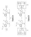
- FIG. 1a shows a single-channel optical transmission system TS.
- the optical transmission system TS comprises a transmitter TX, a receiver RX and a link Lk.
- the transmitter TX is adapted to transmit an optical signal at a transmission wavelength through the link Lk.
- the link Lk comprises m cascaded spans s1, ... sm of optical fiber.
- m is equal to 1
- the optical transmission system is typically referred to as a "single-span transmission system”.
- all the spans have the same length "I”.
- each span s1, ... sm may comprise a respective amplifier A1, ... Am.
- the optical signal is received at the receiver RX.
- FIG. 1b shows a WDM transmission system TS'.
- the WDM transmission system of Figure 1b is adapted to transmit n channels (with n being an integer >1) from a transmitting equipment TE to a receiving equipment RE.
- the transmitting equipment TE comprises n transmitters TX1, TX2, ... TXn. Each transmitter is adapted to transmit at a transmission wavelength of a WDM (e.g. Dense WDM or Coarse WDM) channel grid.
- the transmitting equipment TE further comprises a multiplexer MUX, which is adapted to receive the n optical signals from the transmitters TX1, TX2, ... TXn, to multiplex them and transmit them along a link Lk.
- a multiplexer MUX which is adapted to receive the n optical signals from the transmitters TX1, TX2, ... TXn, to multiplex them and transmit them along a link Lk.
- the receiving equipment RE comprises a demultiplexer DMUX, which is adapted to receive the n optical signals incoming from the link Lk and to demultiplex them. After demultiplexing, the demultiplexer DMUX sends each optical signal to a respective receiver RX1, RX2, ... RXn.
- the link Lk is similar to the link Lk of Figure 1a; thus, a description of the link Lk of Figure 1b will not be repeated.
- each span s1, ... sm comprises a respective dispersion compensator DC1, ... DCm.
- each dispersion compensator is inserted between the respective span and the respective amplifier.
- the amplifiers A1, ... Am are two-stage amplifiers, the dispersion compensator may also be inserted between the two stages of the respective amplifier.
- Figure 2a qualitatively shows the accumulated dispersion AD, as a function of the propagation coordinate z, of an optical signal transmitted either into the single-channel transmission system TS of Figure 1a or in the WDM transmission system TS' of Figure 1b.
- the graph of Figure 2a is not in scale.
- the accumulated dispersion AD is defined as the product of the chromatic dispersion of an optical fiber and the length of said optical fiber.
- the accumulated dispersion of an optical signal which has traveled over a length z of an optical fiber, is D*z, wherein D is the chromatic dispersion of the optical fiber.
- the accumulated chromatic dispersion is D*I, as shown in Figure 2a.
- a dispersion compensator DC1 is provided; thus, the accumulated dispersion of the optical signal is reduced to a value which is lower than D*I (for instance, in Figure 2a such a value is equal to zero).
- the dispersion compensator DC2 reduces again the accumulated dispersion of the optical signal to a value which is lower than D*I (for instance, in Figure 2a such a value is equal to zero). And so on, until the last span sm, wherein the compensator DCm reduces the accumulated dispersion of the optical signal to a value which is comprised within an accumulated dispersion range [ADmin, ADmax].
- Figure 2a shows an ideal case wherein all the spans s1, s2, ... sm have the same length I, thus introducing the same accumulated dispersion D*I. Furthermore, it is assumed that the dispersion compensators DC1, DC2, ... DCM totally compensate the accumulated dispersion D*I introduced by each span, so that, at the beginning of each span, the residual accumulated dispersion of the optical signal is equal to zero. This is of course a simplification, as in real optical transmission systems spans generally have different lengths, and residual accumulated dispersions are different from zero.
- Figure 2b qualitatively shows the accumulated dispersion AD, as a function of the propagation coordinate z, of an optical signal transmitted into an optical transmission system according to the present invention, as it will be explained in further detail herein after.
- the graph of Figure 2b is not in scale.
- the basic idea of the method according to the present invention is transmitting an optical signal at a transmission wavelength such that the accumulated dispersion of the optical signal always increases during propagation along the link Lk, and the accumulated dispersion at the end of the link Lk is comprised within a tolerated accumulated dispersion range.
- the present invention provides a method for properly selecting said transmission wavelength, such that the chromatic dispersion of the optical fiber comprised into the link is such that ADmin ⁇ D*L ⁇ ADmax.
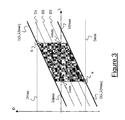
- Figure 3 shows a diagram of the chromatic dispersion versus wavelength which is adapted to select a transmission wavelength of an optical signal according to a first embodiment of the present invention.
- chromatic dispersion of an optical fiber is a function of the wavelength.
- Optical fibers typically used in optical transmission systems have chromatic dispersion curves with the following features:
- the chromatic dispersion curve must be comprised between a minimum chromatic dispersion curve and a maximum chromatic dispersion curve.
- S0max is the dispersion slope
- ⁇ 0min is the minimum zero dispersion wavelength
- ⁇ 0max is the maximum zero dispersion wavelength.
- the values of S0max, ⁇ 0min and ⁇ 0max can be provided either by ITU-T Recommendations or by fiber specifications provided by fiber suppliers.
- Figure 3 shows a maximum chromatic dispersion curve D( ⁇ , ⁇ 0min) and a minimum chromatic dispersion curve D( ⁇ , ⁇ 0max), as defined by equations (1) and (2).
- the term "fiber group” will refer to the ensemble of all the optical fibers of a given fiber type, i.e. to the ensemble of all the optical fibers whose chromatic dispersion curves are substantially parallel to D( ⁇ , ⁇ 0min) and D( ⁇ , ⁇ 0max) and are comprised between D( ⁇ , ⁇ 0min) and D( ⁇ , ⁇ 0max).
- Figure 3 shows three chromatic dispersion curves D1, D2, D3, which are associated to three different optical fibers belonging to the fiber group defined by D( ⁇ , ⁇ 0min) and D( ⁇ , ⁇ 0max).
- the maximum chromatic dispersion curve D( ⁇ , ⁇ 0min) is equal to zero at a zero dispersion wavelength ⁇ 0min, while the minimum chromatic dispersion curve D( ⁇ , ⁇ 0max) is equal to zero at a zero dispersion wavelength ⁇ 0max.
- ⁇ 0min is equal to 1300 nm, while ⁇ 0max is equal to 1324 nm.
- the method according to the present invention comprises providing a tolerated accumulated dispersion range [ADmin; ADmax].
- the method for estimating such a tolerated accumulated dispersion range [ADmin; ADmax] is not an object of the present invention.
- a wavelength sub-range can be estimated, wherein both chromatic dispersion curves D( ⁇ , ⁇ 0min) and D( ⁇ , ⁇ 0max) are comprised between Dmin and Dmax.
- a wavelength sub-range has a minimum wavelength ⁇ min which can be defined as the wavelength wherein the curve D( ⁇ , ⁇ 0max) is equal to Dmin (point "a” in Figure 3), and a maximum wavelength ⁇ max which can be defined as the wavelength wherein the curve D( ⁇ , ⁇ 0min) is equal to Dmax (point "b” in Figure 3).
- the optical signal after propagation along a link Lk whose length is L, the optical signal will have an accumulated chromatic dispersion comprised within the tolerated accumulated chromatic dispersion range [ADmin; ADmax].
- the optical transmission system is provided with a transmitter, which is adapted to transmit an optical signal at a transmission wavelength ⁇ t comprised within the wavelength sub-range [ ⁇ min; ⁇ max].
- a transmitter having a transmission wavelength ⁇ t transmits an optical signal at an actual transmission wavelength which is comprised between ⁇ t- ⁇ t e ⁇ t+ ⁇ t, wherein ⁇ t is the transmission wavelength tolerance of the transmitter.
- the transmission wavelength tolerance ⁇ t must be such that ⁇ t- ⁇ t is higher than or equal to ⁇ min, and ⁇ t+ ⁇ t is lower than or equal to ⁇ max, as shown in Figure 3.
- ⁇ 0min is equal to 1300 nm and ⁇ 0max is equal to 1324 nm.
- Dmin is equal to 1308 nm
- ⁇ max is equal to 1316 nm.
- the transmitter may have a transmission wavelength ⁇ t equal to 1312 nm, with a transmission wavelength tolerance of ⁇ t lower than or equal to 4 nm. It has to be noticed that a tolerance of 4 nm can be obtained with a relatively low cost transmitter, thus obtaining an overall reduction of the optical transmission system cost.
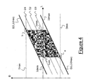
- Figure 4 shows a second embodiment of the present invention, wherein the wavelength sub-range [ ⁇ min; ⁇ max] is used to implement a multi-channel transmission system (for instance, a Dense WDM transmission system or a Coarse WDM transmission system).
- a multi-channel transmission system for instance, a Dense WDM transmission system or a Coarse WDM transmission system.
- two optical signals with two different transmission wavelengths are transmitted. Of coarse, a higher number of channels could be provided.
- the wavelength sub-range [ ⁇ min; ⁇ max] is estimated by applying the method as described with reference to Figure 3.
- the optical transmission system is provided with two transmitters, each transmitter being adapted to transmit a respective optical signal at a respective transmission wavelength ⁇ t1, ⁇ t2, which is comprised within the wavelength sub-range [ ⁇ min; ⁇ max].
- both transmitters have transmission wavelengths ⁇ t1, ⁇ t2 and a transmission wavelength tolerance such that the transmission wavelength tolerance ranges [ ⁇ t1- ⁇ t'; ⁇ t1+ ⁇ t'] and [ ⁇ t2- ⁇ t'; ⁇ t2+ ⁇ t'] are comprised within the wavelength sub-range [ ⁇ min; ⁇ max] and do not overlap each other.
- the two transmission wavelength tolerance ranges [ ⁇ t1- ⁇ t'; ⁇ t1+ ⁇ t'] and [ ⁇ t2- ⁇ t'; ⁇ t2+ ⁇ t'] must be separated by a wavelength interval (as shown in Figure 4), whose width depends on the characteristics of filters, multiplexers and other wavelength-dependent components of the WDM transmission system. Thus, this requires more stable transmitters, with smaller transmission wavelength tolerance.
- the method for selecting the transmission wavelength of an optical signal provides, besides the first and the second embodiment shown in Figures 3 and 4 respectively, further embodiments.
- the wavelength range [ ⁇ 0min; ⁇ 0max] is divided into a number of wavelength sub-ranges.
- An optical signal transmitted at any wavelength comprised within each of said wavelength sub-ranges is affected by a chromatic dispersion comprised within a tolerated chromatic dispersion range, in case said optical signal propagates along any optical fiber belonging to a fiber sub-group of the fiber group defined by D( ⁇ , ⁇ 0min) and D( ⁇ , ⁇ 0max).
- Figure 5 shows a case wherein no wavelength comprised within the wavelength range [ ⁇ 0min; ⁇ 0max] is such that both D( ⁇ , ⁇ 0min) and D( ⁇ , ⁇ 0max) are comprised between Dmin and Dmax. This is due to the fact that the point "a"' of intersection between D( ⁇ , ⁇ 0max) and Dmin' shifts towards higher wavelengths, while the point “b"' of intersection between D( ⁇ , ⁇ 0min) and Dmax' shifts towards lower wavelengths, until a' is on the right of b'. This may happen, for instance, when the link length L increases; this reduces the tolerated chromatic dispersion range [Dmin, Dmax] to a new tolerated chromatic dispersion range [Dmin', Dmax'], which is narrower.
- Figure 6 shows a third embodiment of the invention, which can be implemented when the situation shown in Figure 5 occurs.
- Figure 6 shows the two curves D( ⁇ , ⁇ 0min) and D( ⁇ , ⁇ 0max), defining a fiber group.
- Figure 6 also shows the new tolerated chromatic dispersion range [Dmin', Dmax'].
- the wavelength range [ ⁇ 0min; ⁇ 0max] is divided into a number N of nonoverlapping contiguous wavelength sub-ranges, wherein N is an integer equal to or higher than 2.
- N is an integer equal to or higher than 2.
- four sub-ranges SR1, SR2, SR3, SR4 are shown; the optimum number N of wavelength sub-ranges is chosen according to criteria which will be explained herein after.
- the fiber group defined by D( ⁇ , ⁇ 0min) and D( ⁇ , ⁇ 0max) is divided into four fiber sub-groups. Each sub-group is associated to a respective wavelength sub-range SR1, SR2, SR3 and SR4, and it is defined as follows:
- the optical transmission system is provided with a transmitter which is adapted to transmit an optical signal at a transmission wavelength ⁇ t.
- the transmission wavelength ⁇ t is a wavelength of a discrete set of wavelengths ⁇ 1, ⁇ 2, ⁇ 3, ⁇ 4 ⁇ ; each of the wavelengths ⁇ 1, ⁇ 2, ⁇ 3, ⁇ 4 is comprised within a respective wavelength sub-range SR1, SR2, SR3, SR4, as shown in Figure 6.
- the transmitter is discretely tunable.
- the transmitter may comprise a number N of laser sources (four, by referring to Figure 6), each laser source being adapted to transmit an optical signal at a respective wavelength ⁇ 1, ⁇ 2, ⁇ 3, ⁇ 4.
- the above-described discretely-tunable transmitter may be employed, for instance, in an optical transmission system, wherein the link comprises an optical fiber whose type (G.652, G.653, G.655 or the like) is known, whilst the specific chromatic dispersion curve is unknown.
- the optical fiber necessarily belongs to one of the fiber sub-groups; thus, one of the wavelengths ⁇ 1, ⁇ 2, ⁇ 3, ⁇ 4 ⁇ is comprised within the wavelength sub-range associated to the fiber sub-group comprising the optical fiber.
- This wavelength can simply be found by measuring the performance of the optical transmission system by transmitting an optical signal at each of the four wavelengths ⁇ 1, ⁇ 2, ⁇ 3, ⁇ 4.
- the transmission wavelength ⁇ t is selected as follows:
- N is as low as possible.
- each transmitter is adapted to transmit at a wavelength ⁇ 1, ⁇ 2, ⁇ 3 or ⁇ 4.
- the transmission wavelength can be selected by plugging each of the transmitters into the transmission board of a transmission system, and by measuring the system performances in these four cases.
- a continuously tunable transmitter can be employed, which comprises a single tunable laser source.
- the Applicant is of the opinion that when either a discretely tunable transmitter or a continuously tunable transmitter is employed, the cost of the optical transmission system according to the present invention is still lower than the cost of optical transmission systems implementing the known dispersion compensation technique.
- Figure 7 shows a diagram of the chromatic dispersion versus wavelength which is adapted to select a transmission wavelength of an optical signal according to a fourth embodiment of the present invention.
- a wavelength sub-range is used for implementing a multi-channel transmission system (e.g. a WDM transmission system).
- a multi-channel transmission system e.g. a WDM transmission system.
- two different optical signals at two different transmission wavelengths are transmitted.
- a first transmitter is adapted to transmit a first optical signal at a first transmission wavelength ⁇ t1; said first transmission wavelength ⁇ t1 is a wavelength of a first discrete set of first wavelengths ⁇ 1, ⁇ 2, ⁇ 3, ⁇ 4 ⁇ ; each of the first wavelengths ⁇ 1, ⁇ 2, ⁇ 3, ⁇ 4 is comprised within a respective wavelength sub-range SR1, SR2, SR3, SR4, as shown in Figure 7.
- a second transmitter is adapted to transmit a second optical signal at a second transmission wavelength ⁇ t2; said second transmission wavelength ⁇ t2 is a wavelength of a second discrete set of second wavelengths ⁇ 1', ⁇ 2', ⁇ 3', ⁇ 4' ⁇ ; each of the second wavelengths ⁇ 1', ⁇ 2', ⁇ 3', ⁇ 4' is comprised within a respective wavelength sub-range SR1, SR2, SR3, SR4.
- the second wavelengths are different from the first wavelengths ⁇ 1, ⁇ 2, ⁇ 3, ⁇ 4, as also shown in Figure 7.
- Each of such transmitters may be implemented, as already mentioned, either as a discretely tunable transmitter, or as a set of N separated transmitters, or as a continuously tunable transmitters.
- the first and the second transmission wavelengths ⁇ t1, ⁇ t2 will be chosen as follows:
Landscapes
- Engineering & Computer Science (AREA)
- Computer Networks & Wireless Communication (AREA)
- Signal Processing (AREA)
- Physics & Mathematics (AREA)
- Electromagnetism (AREA)
- Optical Communication System (AREA)
- Optical Fibers, Optical Fiber Cores, And Optical Fiber Bundles (AREA)
Priority Applications (7)
| Application Number | Priority Date | Filing Date | Title |
|---|---|---|---|
| EP05291018A EP1722495B1 (fr) | 2005-05-11 | 2005-05-11 | Procédé de transmission d'un signal optique dans un système de transmission optique, et système de transmission optique correspondant |
| PL05291018T PL1722495T3 (pl) | 2005-05-11 | 2005-05-11 | Sposób transmitowania sygnału optycznego w optycznym systemie transmisji i optyczny system transmisji do zastosowania tego sposobu |
| DE602005013497T DE602005013497D1 (de) | 2005-05-11 | 2005-05-11 | Verfahren zur Übertragung eines optischen Signals in einem optischen Übertragungssystem, und dazugehöriges Übertragungssystem |
| AT05291018T ATE426960T1 (de) | 2005-05-11 | 2005-05-11 | Verfahren zur ubertragung eines optischen signals in einem optischen ubertragungssystem, und dazugehíriges ubertragungssystem |
| ES05291018T ES2323882T3 (es) | 2005-05-11 | 2005-05-11 | Metodo para transmitir una señal optica en un sistema de transmision optica y sistema de transmision optica para implementar dicho metodo. |
| US11/412,747 US7881610B2 (en) | 2005-05-11 | 2006-04-28 | Method of transmitting an optical signal in an optical transmission system and optical transmission system for implementing such a method |
| CN2006100802050A CN1863028B (zh) | 2005-05-11 | 2006-05-11 | 传输光信号的方法和实现该方法的光传输系统 |
Applications Claiming Priority (1)
| Application Number | Priority Date | Filing Date | Title |
|---|---|---|---|
| EP05291018A EP1722495B1 (fr) | 2005-05-11 | 2005-05-11 | Procédé de transmission d'un signal optique dans un système de transmission optique, et système de transmission optique correspondant |
Publications (2)
| Publication Number | Publication Date |
|---|---|
| EP1722495A1 true EP1722495A1 (fr) | 2006-11-15 |
| EP1722495B1 EP1722495B1 (fr) | 2009-03-25 |
Family
ID=34942273
Family Applications (1)
| Application Number | Title | Priority Date | Filing Date |
|---|---|---|---|
| EP05291018A Expired - Lifetime EP1722495B1 (fr) | 2005-05-11 | 2005-05-11 | Procédé de transmission d'un signal optique dans un système de transmission optique, et système de transmission optique correspondant |
Country Status (7)
| Country | Link |
|---|---|
| US (1) | US7881610B2 (fr) |
| EP (1) | EP1722495B1 (fr) |
| CN (1) | CN1863028B (fr) |
| AT (1) | ATE426960T1 (fr) |
| DE (1) | DE602005013497D1 (fr) |
| ES (1) | ES2323882T3 (fr) |
| PL (1) | PL1722495T3 (fr) |
Families Citing this family (3)
| Publication number | Priority date | Publication date | Assignee | Title |
|---|---|---|---|---|
| US7918733B2 (en) * | 2002-07-27 | 2011-04-05 | Sony Computer Entertainment America Inc. | Multi-input game control mixer |
| EP2139129B1 (fr) * | 2008-06-27 | 2013-03-27 | France Telecom | Procédé de limitation du bruit de phase non-lineaire d'un signal optique module en phase a amplitude constante et dispositif associé |
| CN107276676A (zh) * | 2016-04-07 | 2017-10-20 | 四川泰富地面北斗科技股份有限公司 | 一种静态波长交叉色散补偿方法及链路 |
Citations (4)
| Publication number | Priority date | Publication date | Assignee | Title |
|---|---|---|---|---|
| US5809196A (en) * | 1995-12-08 | 1998-09-15 | Pirelli Cavi S.P.A. | Dispersion-shifted optical fibers for wavelength division multiplexing |
| WO1999043118A1 (fr) * | 1998-02-20 | 1999-08-26 | Mci Worldcom, Inc. | Mrl dense dans la bande 1310nm |
| US6055352A (en) * | 1997-08-29 | 2000-04-25 | Lucent Technologies | Optical wavelength optimization for high speed WDM transmission system |
| US20040190840A1 (en) * | 2000-12-12 | 2004-09-30 | Deutsch Bernhard A.M. | Lightwave guide cable and process for carrying an optical signal, especially with respect to multiple waveguide techniques |
Family Cites Families (13)
| Publication number | Priority date | Publication date | Assignee | Title |
|---|---|---|---|---|
| US5224183A (en) * | 1992-07-23 | 1993-06-29 | Alcatel Network Systems, Inc. | Multiple wavelength division multiplexing signal compensation system and method using same |
| JP3396270B2 (ja) * | 1993-08-10 | 2003-04-14 | 富士通株式会社 | 光分散補償方式 |
| US5528612A (en) * | 1993-11-19 | 1996-06-18 | The United States Of America As Represented By The Secretary Of The Navy | Laser with multiple gain elements |
| US5425039A (en) * | 1994-02-24 | 1995-06-13 | Micron Optics, Inc. | Single-frequency fiber Fabry-Perot micro lasers |
| DE4411063A1 (de) * | 1994-03-30 | 1995-10-05 | Sel Alcatel Ag | Verfahren zur Bestimmung der Dispersionsnullstelle eines Lichtwellenleiters |
| US6043914A (en) * | 1998-06-29 | 2000-03-28 | Mci Communications Corporation | Dense WDM in the 1310 nm band |
| JP2001285323A (ja) * | 2000-04-03 | 2001-10-12 | Hitachi Ltd | 光ネットワーク |
| DE10127345A1 (de) * | 2001-06-06 | 2003-01-16 | Siemens Ag | Optisches Übertragungssystem zur hochbitratigen Übertragung von optischen Signalen mit Dispersionskompensationseinheiten |
| US6798500B2 (en) * | 2002-03-05 | 2004-09-28 | Jds Uniphase Corporation | Method for estimation of chromatic dispersion in multichannel optical network spans and chromatic dispersion monitor therefore |
| US6901195B2 (en) * | 2002-05-30 | 2005-05-31 | The Furukawa Electric Co. Ltd. | Optical fiber and an optical transmission system using the optical fiber |
| JP2004037503A (ja) * | 2002-06-28 | 2004-02-05 | Furukawa Electric Co Ltd:The | 光ファイバ |
| US7580639B2 (en) * | 2003-12-29 | 2009-08-25 | Verizon Business Global Llc | Characterization and control of optical dispersion compensating element |
| US7221439B2 (en) * | 2005-04-29 | 2007-05-22 | Corning Incorporated | Method of estimating and measuring longitudinal dispersion in optical fibers |
-
2005
- 2005-05-11 EP EP05291018A patent/EP1722495B1/fr not_active Expired - Lifetime
- 2005-05-11 ES ES05291018T patent/ES2323882T3/es not_active Expired - Lifetime
- 2005-05-11 PL PL05291018T patent/PL1722495T3/pl unknown
- 2005-05-11 DE DE602005013497T patent/DE602005013497D1/de not_active Expired - Lifetime
- 2005-05-11 AT AT05291018T patent/ATE426960T1/de not_active IP Right Cessation
-
2006
- 2006-04-28 US US11/412,747 patent/US7881610B2/en not_active Expired - Fee Related
- 2006-05-11 CN CN2006100802050A patent/CN1863028B/zh not_active Expired - Fee Related
Patent Citations (4)
| Publication number | Priority date | Publication date | Assignee | Title |
|---|---|---|---|---|
| US5809196A (en) * | 1995-12-08 | 1998-09-15 | Pirelli Cavi S.P.A. | Dispersion-shifted optical fibers for wavelength division multiplexing |
| US6055352A (en) * | 1997-08-29 | 2000-04-25 | Lucent Technologies | Optical wavelength optimization for high speed WDM transmission system |
| WO1999043118A1 (fr) * | 1998-02-20 | 1999-08-26 | Mci Worldcom, Inc. | Mrl dense dans la bande 1310nm |
| US20040190840A1 (en) * | 2000-12-12 | 2004-09-30 | Deutsch Bernhard A.M. | Lightwave guide cable and process for carrying an optical signal, especially with respect to multiple waveguide techniques |
Also Published As
| Publication number | Publication date |
|---|---|
| CN1863028A (zh) | 2006-11-15 |
| ES2323882T3 (es) | 2009-07-27 |
| US7881610B2 (en) | 2011-02-01 |
| CN1863028B (zh) | 2011-09-14 |
| EP1722495B1 (fr) | 2009-03-25 |
| PL1722495T3 (pl) | 2009-08-31 |
| DE602005013497D1 (de) | 2009-05-07 |
| US20060257087A1 (en) | 2006-11-16 |
| ATE426960T1 (de) | 2009-04-15 |
Similar Documents
| Publication | Publication Date | Title |
|---|---|---|
| US7751706B2 (en) | Chromatic dispersion compensating apparatus | |
| US8320772B2 (en) | Optical transmission apparatus | |
| US8265485B2 (en) | Optical transmission system and method for chromatic dispersion compensation | |
| US7796897B2 (en) | WDM optical transmission system and WDM optical transmission method | |
| JP4320573B2 (ja) | 光受信方法、光受信装置及びこれを用いた光伝送システム | |
| CN100502276C (zh) | 波分复用光中继传输方法和中继装置 | |
| EP3324558B1 (fr) | Décalage de dispersion de canaux sur côté d'introduction | |
| US9002211B2 (en) | Communication system, dispersion slope imparting section, and method for communicating | |
| US20060067700A1 (en) | Wavelength division multiplexing optical transmission system and wavelength division multiplexing optical transmission method | |
| US20030180051A1 (en) | Wavelength division multiplex transmission system or a polarisation division multiplex system with means for measuring dispersion characteristics, an optical transmitter, an optical receiver and a method therefore | |
| EP1722495B1 (fr) | Procédé de transmission d'un signal optique dans un système de transmission optique, et système de transmission optique correspondant | |
| US20020159119A1 (en) | Method and system for providing dispersion and dispersion slope compensation | |
| WO2002089363A1 (fr) | Procede et systeme de compensation de la dispersion et de la pente de dispersion | |
| US20070047963A1 (en) | Optical transceiver having parallel electronic dispersion compensation channels | |
| JPH09116493A (ja) | 波長多重伝送システム | |
| JP4397854B2 (ja) | 自動分散補償装置 | |
| US6522455B1 (en) | WDM optical communication system having a dispersion slope compensating element | |
| EP0880249A2 (fr) | Système à suppression de mélange de quatre ondes (FWM) | |
| JP3599269B2 (ja) | チャープ光ファイバーグレーティングを通して色分散補正する光信号伝送方法及び本方法を用いた光通信システム | |
| US6577424B1 (en) | Chromatic dispersion compensator providing dispersion compensation to select channels of a wavelength division multiplexed signal | |
| JP2011015267A (ja) | 波長分散補償装置 |
Legal Events
| Date | Code | Title | Description |
|---|---|---|---|
| PUAI | Public reference made under article 153(3) epc to a published international application that has entered the european phase |
Free format text: ORIGINAL CODE: 0009012 |
|
| AK | Designated contracting states |
Kind code of ref document: A1 Designated state(s): AT BE BG CH CY CZ DE DK EE ES FI FR GB GR HU IE IS IT LI LT LU MC NL PL PT RO SE SI SK TR |
|
| AX | Request for extension of the european patent |
Extension state: AL BA HR LV MK YU |
|
| RAP1 | Party data changed (applicant data changed or rights of an application transferred) |
Owner name: ALCATEL LUCENT |
|
| 17P | Request for examination filed |
Effective date: 20070508 |
|
| AKX | Designation fees paid |
Designated state(s): AT BE BG CH CY CZ DE DK EE ES FI FR GB GR HU IE IS IT LI LT LU MC NL PL PT RO SE SI SK TR |
|
| 17Q | First examination report despatched |
Effective date: 20080408 |
|
| GRAP | Despatch of communication of intention to grant a patent |
Free format text: ORIGINAL CODE: EPIDOSNIGR1 |
|
| GRAS | Grant fee paid |
Free format text: ORIGINAL CODE: EPIDOSNIGR3 |
|
| GRAA | (expected) grant |
Free format text: ORIGINAL CODE: 0009210 |
|
| AK | Designated contracting states |
Kind code of ref document: B1 Designated state(s): AT BE BG CH CY CZ DE DK EE ES FI FR GB GR HU IE IS IT LI LT LU MC NL PL PT RO SE SI SK TR |
|
| REG | Reference to a national code |
Ref country code: GB Ref legal event code: FG4D |
|
| REG | Reference to a national code |
Ref country code: CH Ref legal event code: EP |
|
| REG | Reference to a national code |
Ref country code: IE Ref legal event code: FG4D |
|
| REF | Corresponds to: |
Ref document number: 602005013497 Country of ref document: DE Date of ref document: 20090507 Kind code of ref document: P |
|
| REG | Reference to a national code |
Ref country code: ES Ref legal event code: FG2A Ref document number: 2323882 Country of ref document: ES Kind code of ref document: T3 |
|
| PG25 | Lapsed in a contracting state [announced via postgrant information from national office to epo] |
Ref country code: FI Free format text: LAPSE BECAUSE OF FAILURE TO SUBMIT A TRANSLATION OF THE DESCRIPTION OR TO PAY THE FEE WITHIN THE PRESCRIBED TIME-LIMIT Effective date: 20090325 Ref country code: LT Free format text: LAPSE BECAUSE OF FAILURE TO SUBMIT A TRANSLATION OF THE DESCRIPTION OR TO PAY THE FEE WITHIN THE PRESCRIBED TIME-LIMIT Effective date: 20090325 Ref country code: SI Free format text: LAPSE BECAUSE OF FAILURE TO SUBMIT A TRANSLATION OF THE DESCRIPTION OR TO PAY THE FEE WITHIN THE PRESCRIBED TIME-LIMIT Effective date: 20090325 |
|
| PG25 | Lapsed in a contracting state [announced via postgrant information from national office to epo] |
Ref country code: AT Free format text: LAPSE BECAUSE OF FAILURE TO SUBMIT A TRANSLATION OF THE DESCRIPTION OR TO PAY THE FEE WITHIN THE PRESCRIBED TIME-LIMIT Effective date: 20090325 Ref country code: SE Free format text: LAPSE BECAUSE OF FAILURE TO SUBMIT A TRANSLATION OF THE DESCRIPTION OR TO PAY THE FEE WITHIN THE PRESCRIBED TIME-LIMIT Effective date: 20090625 |
|
| REG | Reference to a national code |
Ref country code: PL Ref legal event code: T3 |
|
| NLV1 | Nl: lapsed or annulled due to failure to fulfill the requirements of art. 29p and 29m of the patents act | ||
| PG25 | Lapsed in a contracting state [announced via postgrant information from national office to epo] |
Ref country code: BE Free format text: LAPSE BECAUSE OF FAILURE TO SUBMIT A TRANSLATION OF THE DESCRIPTION OR TO PAY THE FEE WITHIN THE PRESCRIBED TIME-LIMIT Effective date: 20090325 |
|
| PG25 | Lapsed in a contracting state [announced via postgrant information from national office to epo] |
Ref country code: CZ Free format text: LAPSE BECAUSE OF FAILURE TO SUBMIT A TRANSLATION OF THE DESCRIPTION OR TO PAY THE FEE WITHIN THE PRESCRIBED TIME-LIMIT Effective date: 20090325 Ref country code: EE Free format text: LAPSE BECAUSE OF FAILURE TO SUBMIT A TRANSLATION OF THE DESCRIPTION OR TO PAY THE FEE WITHIN THE PRESCRIBED TIME-LIMIT Effective date: 20090325 Ref country code: PT Free format text: LAPSE BECAUSE OF FAILURE TO SUBMIT A TRANSLATION OF THE DESCRIPTION OR TO PAY THE FEE WITHIN THE PRESCRIBED TIME-LIMIT Effective date: 20090901 |
|
| PG25 | Lapsed in a contracting state [announced via postgrant information from national office to epo] |
Ref country code: IS Free format text: LAPSE BECAUSE OF FAILURE TO SUBMIT A TRANSLATION OF THE DESCRIPTION OR TO PAY THE FEE WITHIN THE PRESCRIBED TIME-LIMIT Effective date: 20090725 Ref country code: SK Free format text: LAPSE BECAUSE OF FAILURE TO SUBMIT A TRANSLATION OF THE DESCRIPTION OR TO PAY THE FEE WITHIN THE PRESCRIBED TIME-LIMIT Effective date: 20090325 Ref country code: RO Free format text: LAPSE BECAUSE OF FAILURE TO SUBMIT A TRANSLATION OF THE DESCRIPTION OR TO PAY THE FEE WITHIN THE PRESCRIBED TIME-LIMIT Effective date: 20090325 Ref country code: NL Free format text: LAPSE BECAUSE OF FAILURE TO SUBMIT A TRANSLATION OF THE DESCRIPTION OR TO PAY THE FEE WITHIN THE PRESCRIBED TIME-LIMIT Effective date: 20090325 |
|
| REG | Reference to a national code |
Ref country code: HU Ref legal event code: AG4A Ref document number: E006140 Country of ref document: HU |
|
| PG25 | Lapsed in a contracting state [announced via postgrant information from national office to epo] |
Ref country code: MC Free format text: LAPSE BECAUSE OF NON-PAYMENT OF DUE FEES Effective date: 20090531 |
|
| REG | Reference to a national code |
Ref country code: CH Ref legal event code: PL |
|
| PG25 | Lapsed in a contracting state [announced via postgrant information from national office to epo] |
Ref country code: CH Free format text: LAPSE BECAUSE OF NON-PAYMENT OF DUE FEES Effective date: 20090531 Ref country code: DK Free format text: LAPSE BECAUSE OF FAILURE TO SUBMIT A TRANSLATION OF THE DESCRIPTION OR TO PAY THE FEE WITHIN THE PRESCRIBED TIME-LIMIT Effective date: 20090325 Ref country code: LI Free format text: LAPSE BECAUSE OF NON-PAYMENT OF DUE FEES Effective date: 20090531 Ref country code: BG Free format text: LAPSE BECAUSE OF FAILURE TO SUBMIT A TRANSLATION OF THE DESCRIPTION OR TO PAY THE FEE WITHIN THE PRESCRIBED TIME-LIMIT Effective date: 20090625 |
|
| PLBE | No opposition filed within time limit |
Free format text: ORIGINAL CODE: 0009261 |
|
| STAA | Information on the status of an ep patent application or granted ep patent |
Free format text: STATUS: NO OPPOSITION FILED WITHIN TIME LIMIT |
|
| 26N | No opposition filed |
Effective date: 20091229 |
|
| PG25 | Lapsed in a contracting state [announced via postgrant information from national office to epo] |
Ref country code: IE Free format text: LAPSE BECAUSE OF NON-PAYMENT OF DUE FEES Effective date: 20090511 |
|
| PG25 | Lapsed in a contracting state [announced via postgrant information from national office to epo] |
Ref country code: GR Free format text: LAPSE BECAUSE OF FAILURE TO SUBMIT A TRANSLATION OF THE DESCRIPTION OR TO PAY THE FEE WITHIN THE PRESCRIBED TIME-LIMIT Effective date: 20090626 |
|
| PG25 | Lapsed in a contracting state [announced via postgrant information from national office to epo] |
Ref country code: LU Free format text: LAPSE BECAUSE OF NON-PAYMENT OF DUE FEES Effective date: 20090511 |
|
| PG25 | Lapsed in a contracting state [announced via postgrant information from national office to epo] |
Ref country code: CY Free format text: LAPSE BECAUSE OF FAILURE TO SUBMIT A TRANSLATION OF THE DESCRIPTION OR TO PAY THE FEE WITHIN THE PRESCRIBED TIME-LIMIT Effective date: 20090325 |
|
| REG | Reference to a national code |
Ref country code: GB Ref legal event code: 732E Free format text: REGISTERED BETWEEN 20130926 AND 20131002 |
|
| REG | Reference to a national code |
Ref country code: FR Ref legal event code: GC Effective date: 20131018 |
|
| REG | Reference to a national code |
Ref country code: FR Ref legal event code: PLFP Year of fee payment: 11 |
|
| REG | Reference to a national code |
Ref country code: FR Ref legal event code: CA Effective date: 20150521 |
|
| REG | Reference to a national code |
Ref country code: FR Ref legal event code: CA Effective date: 20150521 |
|
| REG | Reference to a national code |
Ref country code: FR Ref legal event code: PLFP Year of fee payment: 12 |
|
| REG | Reference to a national code |
Ref country code: FR Ref legal event code: PLFP Year of fee payment: 13 |
|
| PGFP | Annual fee paid to national office [announced via postgrant information from national office to epo] |
Ref country code: FR Payment date: 20170523 Year of fee payment: 13 Ref country code: GB Payment date: 20170519 Year of fee payment: 13 Ref country code: DE Payment date: 20170523 Year of fee payment: 13 |
|
| PGFP | Annual fee paid to national office [announced via postgrant information from national office to epo] |
Ref country code: ES Payment date: 20170628 Year of fee payment: 13 Ref country code: IT Payment date: 20170526 Year of fee payment: 13 Ref country code: PL Payment date: 20170421 Year of fee payment: 13 |
|
| PGFP | Annual fee paid to national office [announced via postgrant information from national office to epo] |
Ref country code: TR Payment date: 20170426 Year of fee payment: 13 Ref country code: HU Payment date: 20170519 Year of fee payment: 13 |
|
| REG | Reference to a national code |
Ref country code: DE Ref legal event code: R119 Ref document number: 602005013497 Country of ref document: DE |
|
| GBPC | Gb: european patent ceased through non-payment of renewal fee |
Effective date: 20180511 |
|
| PG25 | Lapsed in a contracting state [announced via postgrant information from national office to epo] |
Ref country code: HU Free format text: LAPSE BECAUSE OF NON-PAYMENT OF DUE FEES Effective date: 20180512 |
|
| PG25 | Lapsed in a contracting state [announced via postgrant information from national office to epo] |
Ref country code: FR Free format text: LAPSE BECAUSE OF NON-PAYMENT OF DUE FEES Effective date: 20180531 Ref country code: DE Free format text: LAPSE BECAUSE OF NON-PAYMENT OF DUE FEES Effective date: 20181201 Ref country code: IT Free format text: LAPSE BECAUSE OF NON-PAYMENT OF DUE FEES Effective date: 20180511 Ref country code: GB Free format text: LAPSE BECAUSE OF NON-PAYMENT OF DUE FEES Effective date: 20180511 |
|
| REG | Reference to a national code |
Ref country code: ES Ref legal event code: FD2A Effective date: 20190913 |
|
| PG25 | Lapsed in a contracting state [announced via postgrant information from national office to epo] |
Ref country code: ES Free format text: LAPSE BECAUSE OF NON-PAYMENT OF DUE FEES Effective date: 20180512 |
|
| PG25 | Lapsed in a contracting state [announced via postgrant information from national office to epo] |
Ref country code: PL Free format text: LAPSE BECAUSE OF NON-PAYMENT OF DUE FEES Effective date: 20180511 |
|
| PG25 | Lapsed in a contracting state [announced via postgrant information from national office to epo] |
Ref country code: TR Free format text: LAPSE BECAUSE OF NON-PAYMENT OF DUE FEES Effective date: 20180511 |