EP1722837B1 - Dispositif a aiguille unique pour le traitement extracorporel du sang - Google Patents
Dispositif a aiguille unique pour le traitement extracorporel du sang Download PDFInfo
- Publication number
- EP1722837B1 EP1722837B1 EP05708587A EP05708587A EP1722837B1 EP 1722837 B1 EP1722837 B1 EP 1722837B1 EP 05708587 A EP05708587 A EP 05708587A EP 05708587 A EP05708587 A EP 05708587A EP 1722837 B1 EP1722837 B1 EP 1722837B1
- Authority
- EP
- European Patent Office
- Prior art keywords
- chamber
- blood
- chambers
- intended
- compartment
- Prior art date
- Legal status (The legal status is an assumption and is not a legal conclusion. Google has not performed a legal analysis and makes no representation as to the accuracy of the status listed.)
- Expired - Lifetime
Links
- 239000008280 blood Substances 0.000 title claims abstract description 103
- 210000004369 blood Anatomy 0.000 title claims abstract description 103
- 238000011282 treatment Methods 0.000 title claims description 54
- 239000012530 fluid Substances 0.000 claims abstract description 40
- 238000004891 communication Methods 0.000 claims abstract description 28
- 230000001105 regulatory effect Effects 0.000 claims description 31
- 230000017531 blood circulation Effects 0.000 claims description 16
- 230000001276 controlling effect Effects 0.000 claims description 14
- 238000011144 upstream manufacturing Methods 0.000 claims description 14
- 238000005259 measurement Methods 0.000 claims description 9
- 230000002209 hydrophobic effect Effects 0.000 claims description 8
- 239000012528 membrane Substances 0.000 claims description 7
- 230000000007 visual effect Effects 0.000 claims description 5
- 230000004872 arterial blood pressure Effects 0.000 claims description 4
- 238000000108 ultra-filtration Methods 0.000 claims description 4
- 241000894006 Bacteria Species 0.000 claims description 3
- 238000010926 purge Methods 0.000 claims description 3
- 238000009530 blood pressure measurement Methods 0.000 claims description 2
- 238000001631 haemodialysis Methods 0.000 claims description 2
- 238000002615 hemofiltration Methods 0.000 claims description 2
- 238000005070 sampling Methods 0.000 abstract 2
- 230000004913 activation Effects 0.000 abstract 1
- 239000003570 air Substances 0.000 description 27
- 230000015271 coagulation Effects 0.000 description 7
- 238000005345 coagulation Methods 0.000 description 7
- 206010016717 Fistula Diseases 0.000 description 4
- 230000003890 fistula Effects 0.000 description 4
- 230000007423 decrease Effects 0.000 description 3
- 230000001435 haemodynamic effect Effects 0.000 description 3
- 230000006872 improvement Effects 0.000 description 3
- 239000007788 liquid Substances 0.000 description 3
- 230000033228 biological regulation Effects 0.000 description 2
- 238000000502 dialysis Methods 0.000 description 2
- 238000003780 insertion Methods 0.000 description 2
- 230000037431 insertion Effects 0.000 description 2
- 238000000034 method Methods 0.000 description 2
- 230000002572 peristaltic effect Effects 0.000 description 2
- 229920000742 Cotton Polymers 0.000 description 1
- 239000012080 ambient air Substances 0.000 description 1
- 230000004888 barrier function Effects 0.000 description 1
- 230000023555 blood coagulation Effects 0.000 description 1
- 230000008859 change Effects 0.000 description 1
- 230000001684 chronic effect Effects 0.000 description 1
- 238000011109 contamination Methods 0.000 description 1
- 230000008878 coupling Effects 0.000 description 1
- 238000010168 coupling process Methods 0.000 description 1
- 238000005859 coupling reaction Methods 0.000 description 1
- 230000003247 decreasing effect Effects 0.000 description 1
- 230000001419 dependent effect Effects 0.000 description 1
- 239000011521 glass Substances 0.000 description 1
- 230000010354 integration Effects 0.000 description 1
- 210000003734 kidney Anatomy 0.000 description 1
- 238000007726 management method Methods 0.000 description 1
- 239000000463 material Substances 0.000 description 1
- 238000005192 partition Methods 0.000 description 1
- 238000002616 plasmapheresis Methods 0.000 description 1
- 230000037452 priming Effects 0.000 description 1
- 230000000306 recurrent effect Effects 0.000 description 1
- 230000002441 reversible effect Effects 0.000 description 1
- 230000009897 systematic effect Effects 0.000 description 1
- 230000002792 vascular Effects 0.000 description 1
Images


Classifications
-
- A—HUMAN NECESSITIES
- A61—MEDICAL OR VETERINARY SCIENCE; HYGIENE
- A61M—DEVICES FOR INTRODUCING MEDIA INTO, OR ONTO, THE BODY; DEVICES FOR TRANSDUCING BODY MEDIA OR FOR TAKING MEDIA FROM THE BODY; DEVICES FOR PRODUCING OR ENDING SLEEP OR STUPOR
- A61M1/00—Suction or pumping devices for medical purposes; Devices for carrying-off, for treatment of, or for carrying-over, body-liquids; Drainage systems
- A61M1/14—Dialysis systems; Artificial kidneys; Blood oxygenators ; Reciprocating systems for treatment of body fluids, e.g. single needle systems for hemofiltration or pheresis
- A61M1/30—Single needle dialysis ; Reciprocating systems, alternately withdrawing blood from and returning it to the patient, e.g. single-lumen-needle dialysis or single needle systems for hemofiltration or pheresis
- A61M1/301—Details
- A61M1/302—Details having a reservoir for withdrawn untreated blood
-
- A—HUMAN NECESSITIES
- A61—MEDICAL OR VETERINARY SCIENCE; HYGIENE
- A61M—DEVICES FOR INTRODUCING MEDIA INTO, OR ONTO, THE BODY; DEVICES FOR TRANSDUCING BODY MEDIA OR FOR TAKING MEDIA FROM THE BODY; DEVICES FOR PRODUCING OR ENDING SLEEP OR STUPOR
- A61M1/00—Suction or pumping devices for medical purposes; Devices for carrying-off, for treatment of, or for carrying-over, body-liquids; Drainage systems
- A61M1/14—Dialysis systems; Artificial kidneys; Blood oxygenators ; Reciprocating systems for treatment of body fluids, e.g. single needle systems for hemofiltration or pheresis
- A61M1/30—Single needle dialysis ; Reciprocating systems, alternately withdrawing blood from and returning it to the patient, e.g. single-lumen-needle dialysis or single needle systems for hemofiltration or pheresis
- A61M1/301—Details
- A61M1/303—Details having a reservoir for treated blood to be returned
-
- A—HUMAN NECESSITIES
- A61—MEDICAL OR VETERINARY SCIENCE; HYGIENE
- A61M—DEVICES FOR INTRODUCING MEDIA INTO, OR ONTO, THE BODY; DEVICES FOR TRANSDUCING BODY MEDIA OR FOR TAKING MEDIA FROM THE BODY; DEVICES FOR PRODUCING OR ENDING SLEEP OR STUPOR
- A61M2205/00—General characteristics of the apparatus
- A61M2205/50—General characteristics of the apparatus with microprocessors or computers
Definitions
- the present invention relates to a device for extracorporeal treatment of blood intended to be connected to a patient by means of a single needle, this device being for example an artificial kidney or a plasmapheresis device.
- the extracorporeal blood circuit to the patient by two modes of operation: the "double-needle” mode and the “single needle” mode.
- the double-needle mode two needles are used: a first for the patient's arterial access, that is to say for taking the blood from the patient, and a second needle for the patient's blood access, that is to say for returning the blood into the patient.
- the blood thus flows in a circuit through which it passes entirely in one direction: first needle, arterial line, then blood compartment of the filter, then venous line, and finally second needle.
- This mode of operation makes it possible to take the blood and give it back simultaneously.
- this mode makes it necessary to insert two needles into the patient, for example in the patient's fistula.
- This double-needle mode is used very widely to obtain good efficiency but it has its limitations, in particular owing to the patient. This is because with successive treatments, at a rate of three sessions per week in the case of a chronic treatment, the patient's fistula may suffer damage and no longer permit advantageous insertion.
- a small fistula may prevent access for both needles, or may then entail insertion of two needles so close to each other that an excessive recirculation phenomenon would reduce the quality of the treatment.
- the "single needle" mode may be opted for.
- a single needle In the single-needle mode, a single needle is inserted into the patient, for example into his or her fistula. There are therefore two separate and alternating phases of operation.
- the first phase is referred to as the arterial phase, during which the blood is taken from the patient via the single needle into the extracorporeal circuit
- the second phase is referred to as the venous phase, during which the blood is passed from the extracorporeal blood circuit back to the patient through the single needle.
- the flow of the blood throughout the extracorporeal circuit, including the needle is not continuous and a certain volume of blood (referred to as the "stroke volume”) has to be stored in the extracorporeal circuit during each cycle of operation. Problems therefore arise concerning the quality and quantity of blood treatment in relation to the session time.
- a plurality of single-needle circuits have been proposed.
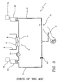
- a first known circuit is schematically represented in Figure 1 .
- the extracorporeal circuit 1 has two clamps, AC (arterial clamp 10) and VC (venous clamp 11), an arterial pump 14, and an expansion chamber 50 with a fixed volume to store the blood being treated.
- AC arterial clamp 10
- VC venous clamp 11
- the patient's blood flows through the arterial line 7 and enters the treatment unit 3 then the venous line 8.
- the clamp 11 VC
- the capacity of the expansion chamber 50 is constant in volume, it contains only air before operation, and the volume of blood stored during operation increases and decreases alternately.
- the pressure in the chamber will be such that the product Volume x Pressure of blood remains constant.
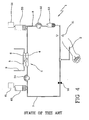
- a second known circuit, proposed in Figure 2 is an improvement of the previous circuit.
- the extracorporeal circuit which is schematically represented includes a second expansion chamber 60 connected to a second dead volume 61, for storing the blood.
- This allows the blood to pass continuously through the dialyser and increases the quality of dialysis treatment. It is, however, necessary for the volume in each of the two expansion chambers to be regulated correctly, so that it is identical and equal to half of the stroke volume: this fairly intricate operation is carried out by an operator.
- Other drawbacks remain: the fluctuating pressure of the blood, the nonoptimized venous phase, the problem of haemocompatibility and coagulation of the blood.
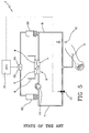
- a third circuit is known and, in Figure 3 , represents an improvement of the circuit in Figure 2 .
- the difference from the second circuit is the position of the arterial pump 14, which is connected downstream of the expansion chamber 60 placed on the arterial line 7, delivering a constant flow rate in the dialyser 3.
- the other drawbacks remain: the intake and delivery pressures vary during the arterial and venous phases, the fluctuating pressure of the blood, the problem of haemocompatibility and coagulation of the blood.
- a second pump 52 has been added downstream of the expansion chamber 50 placed on the venous line, and a bubble trap 53 has been added downstream of the second pump 52 but upstream of the venous clamp 11. This has made it possible to optimize the venous phase, because the flow rate is no longer dictated by the pressure of the expansion chamber 50.
- the haemocompatibility and the undesired coagulation remained problems, however, besides a circuit which has been made more complex.
- a circuit 1 with a single needle 2, disclosed in Patent FR 2 584 906 is known and is illustrated in Figure 5 . It includes an arterial pump 14 and two expansion chambers, arterial 50 and venous 60, for storing the blood.
- a high limit detector 54 (respectively a low limit detector 55) are connected onto the venous expansion chamber 50 for detecting a maximum (respectively minimum) quantity of blood being treated.
- the detected signals are used for control of the arterial and venous phases by a calculation and control unit 15.
- the limit detector includes a pressure value detector for the volume of air contained in each reservoir. The control procedure nevertheless remains intricate, and the problem of haemocompatibility still arises.
- Patent FR 2 672 217 relates, and which is illustrated in Figure 6 , to auto-regulate a device 1 having a single needle 2.
- the circuit 1 includes an arterial clamp 10, an arterial pump 14, an arterial expansion chamber 60, a treatment unit 3, a venous expansion chamber 50 and a venous pump 52.
- Each expansion chamber (50, 60) is connected to pressure regulating means (56 and 66) for maintaining an adjustable, substantially constant pressure in the chamber.
- the regulating means are pumps, which are controlled in order to take air in during an arterial phase, and which are controlled in order to the deliver air during a venous phase, the purpose of this being to maintain a constant pressure on either side of the filter 3 and to set a constant pressure inside the filter.
- Patent Application EP0392304 relates to a single-needle dialysis machine including at least one blood container in the form of a flexible bag arranged between two support plates.
- One of the plates is fixed and the other can be moved, during the venous phase only, in order to control the emptying of the flexible bag.
- the bag becomes filled up to a certain high liquid limit and acts on the free mobile plate.
- the bag is emptied by the pressure exerted by the controlled mobile plate on the entirely flexible bag, until a low liquid level is reached.
- the high and low pressure limits are detected by a pressure detector in the bag.
- This device uses a flexible bag for holding blood and air, but it nevertheless has the problem of haemocompatibility.
- Patent Application EP0462422 discloses a device with at least one blood accumulator which, at least in the venous phase, is supplied with a force produced by an external instrument, so that a pressure essentially independent of its filled volume is formed on the inside.
- the accumulator is therefore inflated like a balloon during the arterial phase, and deflated during the venous phase.
- the management of flow rate and pressure with a deformable flexible bag remains very difficult and not very accurate, especially as the pressure also turns out to be dependent on the elasticity of the bag.
- an extracorporeal blood treatment device 1 ( Fig. 7 ) intended to operate in a mode with a single needle 2, comprising:
- the invention also relates to a disposable device 100 ( Fig. 8 ) for use in an extracorporeal blood circuit 1 with a single needle 2, comprising:
- Figure 7 represents an extracorporeal blood treatment device 1 intended to operate in a mode with a single needle 2, comprising a treatment unit 3 having a first compartment 4 and a second compartment 5, which are separated by a semipermeable membrane 6, an extracorporeal blood circuit comprising a single needle 2, an intake line 7 in fluid communication with the first compartment 4 of the treatment unit 3, the first compartment 4, and a return line 8 in fluid communication with the first compartment 4 of the treatment unit 3, a purge line 9 at the outlet of the second compartment 5, a closure means (10, 11) acting on at least the intake line 7 and the return line 8 in order to generate the alternate sequence of blood intake and return, at least a first chamber 12 which is in fluid communication with the extracorporeal blood circuit and defines a first additional blood volume; the first chamber 12 having a variable total content, being rigid and including at least one wall capable of being moved; the device including a means 19 acting on the chamber 12 in order to modify the volume of the chamber 12.
- the chamber 12 will thus store blood during the arterial phase and release blood during the venous
- the chamber is rigid in so far as it can withstand the deformation forces liable to be induced by a pressure, in particular.
- the material could be plastic, glass, etc.
- the first chamber 12 is in fluid communication with the intake line 7.
- the first chamber 12 is in fluid communication with the return line 8.
- a second embodiment ( Fig. 9 ) relates to the same device with a second chamber 13 which is in fluid communication with the extracorporeal blood circuit and defines a second additional blood volume, the said second chamber 13 having a variable total content making it possible to store blood during the arterial phase and release blood during the venous phase, this chamber 13 being rigid and including at least one wall capable of being moved. More particularly, the second chamber 13 may be in fluid communication with the return line 8 when the first chamber is in fluid communication with the intake line 7.
- a fluid flow-rate regulating means 14 may be present and act on the extracorporeal blood circuit.
- This fluid flow-rate regulating means may include a pump, particularly a peristaltic pump.
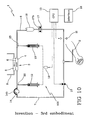
- This pump 14 may act upstream of the first compartment 4 of the treatment unit. More particularly, this pump 14 acts upstream of the first chamber 12 (third embodiment, illustrated in Figure 10 ) or downstream of the first chamber 12 (fourth embodiment, illustrated in Figure 11 ). As an alternative, this pump 14 may act downstream of the first compartment 4 of the treatment unit. In this case, this pump 14 or its equivalent would act either upstream or downstream of the second chamber 13.
- the closure means (10, 11) may be a pump, a valve, an active clamp or a combination of these instruments.
- Two clamps have been represented arbitrarily in the 4 embodiments which are illustrated, the first clamp 11 referred to as the "arterial clamp” acting on the intake line or arterial line 7, and the second clamp 12 referred to as the “venous clamp” acting on the return line or venous line 8.
- An air detector 17 may be placed upstream of the part of the venous closure means (10, 11) acting on the return line 8. A part 17b of the return line will be operational with the air detector.
- An air separator 18 may be inserted into the device. It may be connected downstream of the chamber or chambers (12, 13) and the treatment unit 3. The air separator is advantageously connected upstream of the part of the closure means (10, 11) acting on the return line 8, and immediately upstream of the optional air detector 17. The air separator 18 may also receive the air detector 17 on its own structure. The air separator (18) may include a bubble trap. An air separator may also be inserted into each chamber (12, 13).
- At least one of the chambers may be a rigid chamber with at least one wall intended to slide in the chamber. More particularly, one of the chambers may be a syringe. Such a syringe is advantageously positioned vertically with the needle upwards. These characteristics are illustrated in the first four embodiments.
- the syringe may furthermore include an extensible diaphragm impermeable to bacteria, or to blood, of which at least one part is attached to the plunger and another part is attached to a circumference of the barrel of the syringe, so that it forms a barrier between the blood contained in the syringe and the ambient air.
- the diaphragm could be formed by gauze, cotton, etc.
- the elastic diaphragm 43 impermeable to bacteria connects a point of the plunger to a circumference of the barrel towards the outer part of the latter.
- the diaphragm may be in the form of a concertina, for example, which can expand when the syringe is empty and contract when the syringe is full.
- At least one of the chambers (12, 13) includes an opening to the outside, comprising a hydrophobic diaphragm (41) which is associated with the said opening and makes it possible to remove any undesirable air bubble present in the chamber (12, 13).
- This diaphragm may be placed as close as possible to the outlet of the syringe. It is represented at the top of the barrel. 40 forming the syringe in Figure 15 , although it may be located anywhere on the chamber, on the mobile wall (plunger 42 in Fig. 15 ) or on the fixed wall.
- At least one chamber part (12, 13) may be transparent and include a scale for visual reading of the content. This allows the operator to immediately check the filling state of the chamber or chambers and to ascertain the "stroke volume" SV.
- At least one chamber (12, 13) may be also be integrated inside the treatment unit 3.
- the two chambers (12, 13) advantageously have the same structure and the same maximum content. Once the equipment has been regulated, this makes it possible to distribute the stroke volume into two identical volumes throughout operation.
- a calculation and control unit (CPU) 15 is provided for simultaneously controlling the closure means (10, 11) in order to alternate the arterial phase and the venous phase, and controlling the filling of at least one of the two chambers (12, 13) during the arterial phase and the discharge of at least one of the two chambers (12, 13) during the venous phase.
- the means 19 acting on the chambers (12, 13) in order to modify the volume of the chambers (12, 13) includes at least one actuation means for varying the volume of the chamber by moving at least one chamber wall. It will, for example, include a plunger.
- the means 19 comprises a motor coupled with the actuation means. In the embodiment which includes two identical syringes, the motor will be coupled to the plunger of each syringe. The coupling will be such that the two plungers are actuated simultaneously and in the same position.
- the CPU 15 comprises elements for controlling the means. 19 acting on the chambers (12, 13) for modifying the volume of the chambers (12, 13) in order to fill at least one of the two chambers (12, 13) during the arterial phase, and to discharge at least one of the two chambers (12, 13) during the venous phase.
- the CPU 15 comprises means for controlling the first fluid flow-rate regulating means 14 in order to ensure a substantially constant flow rate immediately downstream of the latter. This improves the quality of the blood treatment.
- the CPU advantageously comprises means for controlling the means acting on the chambers (12, 13) for modifying the volume of the two chambers (12, 13) in order to set a volume in the first chamber 12 substantially equal to the volume in the second chamber 13 during operation of the device.
- a user interface 16 is also provided, with means for receiving intended parameters, the CPU 15 comprising means for calculating control parameters from one or more planned machine parameters.
- the device may also include:
- a first arterial phase is initiated by making the arterial clamp 10 open and the venous clamp 11 close, the blood passes through the needle and the intake line 7, fills the first syringe 12 and enters the first compartment 4 of the treatment unit 3, then the treated blood leaves the compartment 4, passes through the return line and fills the second syringe 13.
- the blood is both stored and purified (in part) through the treatment unit.
- Q B denotes the blood flow rate in the first compartment 4 of the treatment unit 3
- Q D denotes the dialysate flow rate in the second compartment 5
- Q UF denotes the ultrafiltration rate of the patient's fluid taking place through the membrane 6, passing from the first compartment 5 to the second compartment 4.
- the blood flow rate downstream of the treatment unit is accordingly reduced by Q UF .
- the chambers are syringes with the same structure and the same maximum content, equal to the stroke volume (SV) divided by 2.
- the stroke volume SV is the maximum volume taken from the patient during one cycle (during the arterial phase and the venous phase).
- the arterial stroke volume SV A (respectively the venous stroke volume SV v ) denotes the maximum volume taken from the patient and pumped through the "arterial" first chamber 12 (respectively the "venous" second chamber 13).
- the int ended parameters may include the intended blood flow rate Q Bint at the inlet of the first compartment 4.
- the control parameters accordingly include at least the duration of the arterial phase T A and the duration of the venous phase T V .
- At least the actuation speed of the actuation means V ACT during the arterial phase, on the one hand, and during the venous phase, on the other hand, may be selected as control parameters. This is because the actuation speed can be derived from the flow rate and the corresponding phase duration. Measurement of the actuation time and the actuation speed of the syringes, or alternatively measurement of the volumes, or else the first of the two which pertains, may also be used as a reference for changing from one phase to another.
- the calculation and control unit includes means for regulating the blood flow rate Q B around the intended blood flow rate Q Bint as a function of the measured parameters P A and P V . substantial variation around Q Bint : If P V decreases, then Q B will be substantially increased, and vice versa. In a venous phase, there may likewise be a pressure "conflict" between the "arterial" chamber 12 and the pump 14 (due to flow rates which do not match, taking Q UF into account).
- the intended parameters may include the actuation speed V ACTint of the actuation means or, as an alternative to V ACTint , the intended duration of the arterial phase T Aint and the intended duration of the venous phase T Vint .
- the control parameters accordingly include at least the blood flow rate Q B .
- the calculation and control unit includes means for regulating the actuation speed V ACT around the intended actuation speed V ACTint as a function of the measured parameters P A and P V .
- the calculation and control unit will include means for regulating the duration of the arterial phase T A around the intended duration of the arterial phase T Aint and for regulating the duration of the venous phase T V around the intended duration of the venous phase T Vint , as a function of the measured parameters P A and P V .
- the calculation and control unit 15 is also intended to comprise means for controlling the following modes of operation: haemodialysis, haemofiltration, haemodiafiltration.
- the invention also relates to the disposable device (or "disposable") 100 corresponding to the embodiments of the various instruments described above.
- the disposable device of the first embodiment illustrated in Figure 8 , includes a treatment unit 3 having a first compartment 4 and a second compartment 5, which are separated by a semipermeable membrane 6; an extracorporeal blood circuit comprising a single needle 2, an intake line 7, the first compartment 4 of the treatment unit and a return line 8; at least a first chamber 12 for defining a first additional blood volume which includes a connection 22 in fluid communication with the intake line 7 or with the return line 8; the first chamber 12 having a variable total content and being rigid and including at least one wall capable of being moved.
- the first chamber 12 is advantageously in fluid communication with the intake line 7 via the said connection 22, which is fixed or removable.
- the disposable device of the fourth embodiment also includes a second chamber 13 for defining a second additional blood volume which includes a fixed or removable second connection 23 for placing the second chamber 13 in fluid communication with the return line 8, the second chamber 13 having a variable total content and being rigid and including at least one wall capable of being moved.
- the disposable device may include at least one part 14b capable of working with a flow-rate regulating means 14. This part 14b is placed on the intake line 7, downstream of the first connection 22.
- the disposable device may include a part 17b placed on the return line 8 and capable of working with an air detector 17.
- An air separator 18 may be connected onto the return line 8.
- At least one of the chambers (12, 13) may be a rigid chamber with at least one wall intended to slide in the chamber, and will more particularly be a syringe.
- the syringe may include an extensible diaphragm, which is impermeable to blood and of which at least one part is attached to the plunger and another part is attached to a circumference of the barrel of the syringe).
- the syringe may moreover include an opening to the outside, comprising a hydrophobic diaphragm 41 which is associated with the said opening and makes it possible to remove any undesirable air bubble present in the chamber (12, 13).
- at least one part of the chamber or chambers (12, 13) may be transparent and include a scale for visual reading of the storage capacity.
- At least one chamber (12, 13) may also be integrated inside the treatment unit 3.
- the two storage means (12, 13) advantageously have the same structure and the same maximum content. They may be placed side by side in order to facilitate their control by the actuation means. In the case of two syringes, they will be identical and placed side by side, and will have a common linear actuation means for the plungers.
- the syringes may themselves be removable and fittable by virtue of two connectors 22 and 23 on the disposable device, which makes it possible to select and fit the syringes before the treatment, as a function of the intended stroke volume.
- controllable syringes with a variable total content are particularly advantageous because the storage of blood during single-needle operation obviates the use of the expansion chambers in the prior art.
- this obviation makes it possible to reduce coagulation owing to the absence of any air/blood interface, and makes it possible to avoid the compulsory presence of an air separator required downstream of the first chamber and upstream of the treatment unit.
- this obviation makes it possible to avoid having to ascertain and control the parameters of air pressure and air volume in the chambers.
- level detectors or the like are no longer necessary for ascertaining the quantity of blood in the chamber: the position of the plunger or of the mobile partition of the chamber is easy to derive (from the maximum content and the position of the actuation means) and will give its instantaneous content.
- the syringes can furthermore be readily emptied again at the end of the venous phase, so that no blood will remain in the syringe, while maintaining accurate knowledge of the internal volume.
- the syringes furthermore fulfil the function of a pump and will make it possible to reduce the number of pumps needed in order to ensure a maximally constant, known and easily controllable blood flow rate.
- the flow rate of blood through the first compartment of the treatment unit is thus kept continuous and substantially constant.
- the invention provides many advantages. It makes it possible:
Landscapes
- Health & Medical Sciences (AREA)
- Heart & Thoracic Surgery (AREA)
- Urology & Nephrology (AREA)
- Anesthesiology (AREA)
- Vascular Medicine (AREA)
- Engineering & Computer Science (AREA)
- Emergency Medicine (AREA)
- Biomedical Technology (AREA)
- Hematology (AREA)
- Life Sciences & Earth Sciences (AREA)
- Animal Behavior & Ethology (AREA)
- General Health & Medical Sciences (AREA)
- Public Health (AREA)
- Veterinary Medicine (AREA)
- External Artificial Organs (AREA)
Claims (59)
- Dispositif pour le traitement extracorporel de sang (1) apte à fonctionner dans un mode à une seule aiguille (2), comprenant:- une unité de traitement (3) ayant un premier compartiment (4) et un deuxième compartiment (5) séparés par une membrane semi-perméable (6),- un circuit extracorporel de sang comprenant une seule aiguille (2), une ligne d'alimentation (7) en communication de fluide avec le premier compartiment (4) de l'unité de traitement (3), le premier compartiment (4), et une ligne de retour (8) en communication de fluide avec le premier compartiment (4) de l'unité de traitement (3),- une ligne d'évacuation (9) à la sortie du deuxième compartiment (5),- un moyen de fermeture (10, 11) agissant sur au moins la ligne d'alimentation (7) et la ligne de retour (8) afin de générer la séquence alternée d'alimentation et restitution de sang,- au moins une première chambre (12) en communication de fluide avec le circuit extracorporel de sang et définissant un premier volume de sang additionnel, la première chambre (12) ayant un contenu total variable;- la première chambre (12) est rigide et comprend au moins une paroi mobile,- le dispositif comprend un moyen (19) agissant sur la chambre (12) afin de modifier le volume de la chambre (12), permettant ainsi de stocker le sang pendant la phase artérielle et de faire sortir le sang pendant la phase veineuse,caractérisé en ce que:la première chambre (12) comporte une ouverture vers l'extérieur, comprenant un diaphragme hydrophobe (41) associé à ladite ouverture et permettant d'éliminer les bulles d'air indésirables éventuellement présentes dans la chambre (12).
- Dispositif selon la revendication 1, caractérisé en ce que la première chambre (12) est en communication de fluide avec la ligne d'alimentation (7).
- Dispositif selon la revendication 1, caractérisé en ce que la première chambre (12) est en communication de fluide avec la ligne de retour (8).
- Dispositif selon la revendication 1, comprenant une deuxième chambre (13) en communication de fluide avec le circuit extracorporel de sang et définissant un deuxième volume de sang additionnel, ladite deuxième chambre (13) étant rigide et comprenant au moins une paroi mobile; la deuxième chambre ayant un contenu total variable permettant de stocker le sang pendant la phase artérielle et de faire sortir le sang pendant la phase veineuse.
- Dispositif selon la revendication 2 et la revendication précédente, où la deuxième chambre (13) est en communication de fluide avec la ligne de retour (8).
- Dispositif selon une des revendications précédentes, comprenant un moyen de réglage du débit de fluide (14) agissant sur le circuit extracorporel de sang, où ledit moyen de réglage du débit de fluide comporte une pompe.
- Dispositif selon la revendication précédente, où ledit moyen de réglage du débit de fluide (14) agit en amont du premier compartiment (4) de l'unité de traitement.
- Dispositif selon la revendication précédente, où ledit moyen de réglage du débit de fluide (14) agit en amont de la première chambre (12).
- Dispositif selon la revendication 7, où ledit moyen de réglage du débit de fluide (14) agit en aval de la première chambre (12).
- Dispositif selon la revendication 6, où ledit moyen de réglage du débit de fluide (14) agit en aval du premier compartiment (4) de l'unité de traitement.
- Dispositif selon la revendication 10, où ledit moyen de réglage du débit de fluide (14) agit en amont de la deuxième chambre (13).
- Dispositif selon la revendication 10, où ledit moyen de réglage du débit de fluide (14) agit en aval de la deuxième chambre (13).
- Dispositif selon une des revendications précédentes, comprenant au moins un détecteur d'air (17) placé en amont de la partie du moyen de fermeture veineuse (10, 11) agissant sur la ligne de retour (8).
- Dispositif selon une des revendications précédentes, comprenant au moins un séparateur d'air (18).
- Dispositif selon la revendication précédente, où le séparateur d'air est relié en aval de la chambre ou des chambres (12, 13) et de l'unité de traitement (3), et directement en amont du détecteur d'air (17).
- Dispositif selon une des revendications 14 à 15, où le séparateur d'air (18) comporte un piège à bulles.
- Dispositif selon une des revendications 14 et 15, où le séparateur d'air (18) est installé dans chaque chambre (12, 13).
- Dispositif selon une des revendications précédentes, où au moins une des chambres (12, 13) est une chambre rigide avec au moins une paroi apte à glisser dans la chambre.
- Dispositif selon la revendication précédente, où au moins une des chambres est une syringe.
- Dispositif selon la revendication précédente, où au moins une syringe est positionnée verticalement avec la sortie de l'aiguille vers le haut.
- Dispositif selon la revendication 19 ou 20, où la syringe comprend un diaphragme extensible et imperméable aux bactéries, dont au moins une partie est fixée au piston et une autre partie est fixée à une circonférence du cylindre de la syringe.
- Dispositif selon une des revendications 4 à la précédente, où la deuxième chambre (13) comporte une ouverture vers l'extérieur, comprenant un diaphragme hydrophobe (41) associé à ladite ouverture et permettant d'éliminer les bulles d'air indésirables éventuellement présentes dans la deuxième chambre (13).
- Dispositif selon une des revendications 19 à 22, où au moins une partie des chambres (12, 13) est transparente et comporte une échelle pour la lecture visuelle du contenu.
- Dispositif selon une des revendications précédentes, où au moins une chambre (12, 13) est intégrée dans l'unité de traitement (3).
- Dispositif selon une des revendications 19 à 24, où les deux chambres (12, 13) ont la même structure et le même contenu maximum.
- Dispositif selon une des revendications précédentes, comprenant une unité de calcul et de commande (15) pour:a. commander simultanément les moyens de fermeture (10, 11) afin d'alterner la phase artérielle et la phase veineuse, etb. commander le remplissage d'au moins une des deux chambres (12, 13) pendant la phase artérielle et l'évacuation d'au moins une des deux chambres (12, 13) pendant la phase veineuse.
- Dispositif selon une des revendications précédentes, où le moyen (19) agissant sur les chambres (12, 13) pour varier le volume des chambres (12, 13) comprend un moyen d'actionnement pour varier le volume de la chambre en déplaçant au moins une paroi de la chambre, dans ce cas-là ce moyen pouvant comporter un piston.
- Dispositif selon la revendication précédente, où ledit moyen (19) comprend un moteur couplé au moyen d'actionnement.
- Dispositif selon une des revendications 26 à 28, où l'unité de calcul et de commande (15) comprend des moyens pour commander le moyen (19) agissant sur les chambres (12, 13) pour varier le volume des chambres (12, 13) afin de remplir au moins une des deux chambres (12, 13) pendant la phase artérielle, et d'évacuer au moins une des deux chambres (12, 13) pendant la phase veineuse.
- Dispositif selon une des revendications 26 à 29, où l'unité de calcul et de commande (15) comprend des moyens pour commander le premier moyen de réglage du débit de fluide (14) afin d'assurer un débit substantiellement constant directement en aval de celui-ci.
- Dispositif selon une des revendications 26 à 30, où l'unité de calcul et de commande (15) comprend des moyens pour commander le moyen pour varier le volume des deux chambres (12, 13) afin d'établir un volume dans la première chambre (12) substantiellement égal au volume dans la deuxième chambre (13) pendant le fonctionnement du dispositif.
- Dispositif selon une des revendications 26 à 31, comprenant:i. une interface utilisateur (16) pour recevoir les paramètres prévus;ii. des moyens de mesure pour établir les paramètres mesurés;iii. où le moyen de calcul et de commande (15) comprend des moyens pour calculer les paramètres de commande à partir d'un ou plusieurs paramètres prévus et d'un ou plusieurs paramètres mesurés, et pour commander le dispositif en fonction de ces paramètres.
- Dispositif selon la revendication précédente, où les moyens de mesure comprennent des moyens de mesure de la pression (PA, PV) pour mesurer la pression artérielle et la pression veineuse.
- Dispositif selon la revendication précédente, où les moyens de mesure comprennent au moins un débitmètre (D1, D2) pour établir le débit d'ultrafiltration.
- Dispositif selon la revendication 33 ou 34, où les paramètres prévus comprennent au moins le volume systolique prévu SVint.
- Dispositif selon une des revendications 32 à 35, où les paramètres prévus comprennent le débit sanguin prévu QBint à l'entrée du premier compartiment (4).
- Dispositif selon la revendication précédente, où les paramètres de commande comprennent au moins la durée de la phase artérielle TA et la durée de la phase veineuse TV.
- Dispositif selon la revendication 36, où les paramètres de commande comprennent au moins la vitesse d'actionnement du moyen d'actionnement VACT.
- Dispositif selon la revendication 37 ou 38, où l'unité de calcul et de commande comprend des moyens pour régler le débit sanguin QB autour du débit sanguin prévu QBin, en fonction des paramètres mesurés PA et PV.
- Dispositif selon une des revendications 32 à 35, où les paramètres prévus comprennent la vitesse d'actionnement prévue VACTint du moyen d'actionnement.
- Dispositif selon une des revendications 32 à 35, où les paramètres prévus comprennent la durée prévue de la phase artérielle TAint et la durée prévue de la phase veineuse TVint.
- Dispositif selon une des revendications 40 et 41, où les paramètres de commande comprennent au moins le débit sanguin QB.
- Dispositif selon la revendication 42, où l'unité de calcul et de commande comprend des moyens pour régler la vitesse d'actionnement VACT autour de la vitesse d'actionnement prévue VACTint en fonction des paramètres mesurés PA et PV.
- Dispositif selon la revendication 42, où l'unité de calcul et de commande comprend des moyens pour régler la durée de la phase artérielle TA autour de la durée prévue pour la phase artérielle TAint et pour régler la durée de la phase veineuse TV autour de la durée prévue pour la phase veineuse TVint en fonction des paramètres mesurés PA et PV.
- Dispositif selon une des revendications 26 à 34, où l'unité de calcul et de commande comprend des moyens pour commander les modes de fonctionnement suivants: hémodialyse, hémofiltration, hémodiafiltration.
- Dispositif jetable (100) pour l'emploi dans un circuit extracorporel de sang (1) avec une seule aiguille (2), comprenant:a. une unité de traitement (3) ayant un premier compartiment (4) et un deuxième compartiment (5) séparés par une membrane semi-perméable (6);b. un circuit extracorporel de sang comportant une seule aiguille (2), une ligne d'alimentation (7), le premier compartiment (4) de l'unité de traitement (3) et une ligne de retour (8);c. au moins une première chambre (12) pour définir un volume de sang additionnel, comportant un raccordement (22) en communication de fluide avec la ligne d'alimentation (7) ou avec la ligne de retour (8),d. la première chambre (12) ayant un contenu total variable,e. la première chambre (12) étant rigide et comportant au moins une paroi mobile, caractérisé en ce quef. la première chambre (12) comporte une ouverture vers l'extérieur, comprenant un diaphragme hydrophobe (41) associé à ladite ouverture.
- Dispositif jetable selon la revendication précédente, où la première chambre (12) est en communication de fluide avec la ligne d'alimentation (7) au moyen dudit raccordement (22), qui est fixe ou amovible.
- Dispositif jetable selon la revendication précédente, comprenant une deuxième chambre (13) pour définir un deuxième volume de sang additionnel, qui comporte un deuxième raccordement fixe ou amovible (23) pour mettre la deuxième chambre (13) en communication de fluide avec la ligne de retour (8), la deuxième chambre (13) ayant un contenu total variable, la deuxième chambre (13) étant rigide et comportant au moins une paroi mobile.
- Dispositif jetable selon une des revendications 46 à 48, comprenant au moins une partie (14b) étant à même de coopérer avec un moyen de réglage du débit (14).
- Dispositif jetable selon la revendication précédente, où ladite partie (14b) est placée sur la ligne d'alimentation (7) en aval du premier raccordement (22).
- Dispositif jetable selon une des revendications 46 à 50, comprenant une partie (17b) placée sur la ligne de retour (8) et étant à même de coopérer avec un détecteur d'air (17).
- Dispositif jetable selon une des revendications 46 à 50, comprenant au moins un séparateur d'air (18) branché sur la ligne de retour (8).
- Dispositif jetable selon une des revendications 46 à 52, où au moins une des chambres (12, 13) est une chambre rigide avec au moins une paroi apte à glisser dans la chambre.
- Dispositif jetable selon la revendication précédente, où au moins une chambre (12, 13) est une syringe.
- Dispositif jetable selon la revendication précédente, où la syringe comporte un diaphragme extensible imperméable au sang, dont au moins une partie est fixée au piston et une autre partie est fixée à une circonférence du cylindre de la syringe.
- Dispositif jetable selon une des revendications 46 à la revendication précédente, où la deuxième chambre (13) comporte une ouverture vers l'extérieur, comprenant un diaphragme hydrophobe (41) associé à ladite ouverture.
- Dispositif jetable selon une des revendications 46 à la revendication précédente, où au moins une partie de la chambre ou des chambres (12, 13) est transparente et comprend une échelle pour la lecture visuelle de la capacité de stockage.
- Dispositif jetable selon une des revendications 46 à la revendication précédente, où au moins une chambre (12, 13) est intégrée dans l'unité de traitement (3).
- Dispositif jetable selon une des revendications 46 à la revendication précédente, où les deux moyens de stockage (12, 13) ont la même structure et le même contenu maximum.
Applications Claiming Priority (2)
| Application Number | Priority Date | Filing Date | Title |
|---|---|---|---|
| FR0402381A FR2867079B1 (fr) | 2004-03-08 | 2004-03-08 | Dispositif et procede de commande de la circulation du sang pour un circuit a aiguille unique |
| PCT/IB2005/000468 WO2005092408A1 (fr) | 2004-03-08 | 2005-03-03 | Dispositif a aiguille unique pour le traitement extracorporel du sang |
Publications (2)
| Publication Number | Publication Date |
|---|---|
| EP1722837A1 EP1722837A1 (fr) | 2006-11-22 |
| EP1722837B1 true EP1722837B1 (fr) | 2008-04-30 |
Family
ID=34855122
Family Applications (1)
| Application Number | Title | Priority Date | Filing Date |
|---|---|---|---|
| EP05708587A Expired - Lifetime EP1722837B1 (fr) | 2004-03-08 | 2005-03-03 | Dispositif a aiguille unique pour le traitement extracorporel du sang |
Country Status (8)
| Country | Link |
|---|---|
| EP (1) | EP1722837B1 (fr) |
| AT (1) | ATE393642T1 (fr) |
| AU (1) | AU2005225223B2 (fr) |
| CA (1) | CA2556458A1 (fr) |
| DE (1) | DE602005006392T2 (fr) |
| ES (1) | ES2306100T3 (fr) |
| FR (1) | FR2867079B1 (fr) |
| WO (1) | WO2005092408A1 (fr) |
Families Citing this family (4)
| Publication number | Priority date | Publication date | Assignee | Title |
|---|---|---|---|---|
| US8580110B2 (en) | 2008-04-15 | 2013-11-12 | Gambro Lundia Ab | Blood treatment apparatus |
| US8652082B2 (en) | 2008-04-15 | 2014-02-18 | Gambro Lundia Ab | Blood treatment apparatus |
| ES2573483T3 (es) | 2008-04-15 | 2016-06-08 | Gambro Lundia Ab | Aparato y método de tratamiento de la sangre |
| US12558469B2 (en) * | 2021-08-06 | 2026-02-24 | Fenwal, Inc. | Systems and methods for converting an apheresis fluid processing circuit to single or double needle mode |
Family Cites Families (3)
| Publication number | Priority date | Publication date | Assignee | Title |
|---|---|---|---|---|
| FR2672217B1 (fr) * | 1991-02-06 | 1998-09-11 | Hospal Ind | Circuit de circulation extracorporelle de sang a aiguille unique pour dispositif de traitement du sang. |
| DE19936294A1 (de) * | 1999-08-02 | 2001-02-15 | Hans Mueller | Spritze |
| DE10042324C1 (de) * | 2000-08-29 | 2002-02-07 | Fresenius Medical Care De Gmbh | Blutbehandlungseinrichtung und Disposable für eine Blutbehandlungseinrichtung |
-
2004
- 2004-03-08 FR FR0402381A patent/FR2867079B1/fr not_active Expired - Fee Related
-
2005
- 2005-03-03 CA CA002556458A patent/CA2556458A1/fr not_active Abandoned
- 2005-03-03 AT AT05708587T patent/ATE393642T1/de not_active IP Right Cessation
- 2005-03-03 WO PCT/IB2005/000468 patent/WO2005092408A1/fr not_active Ceased
- 2005-03-03 DE DE602005006392T patent/DE602005006392T2/de not_active Expired - Lifetime
- 2005-03-03 ES ES05708587T patent/ES2306100T3/es not_active Expired - Lifetime
- 2005-03-03 AU AU2005225223A patent/AU2005225223B2/en not_active Ceased
- 2005-03-03 EP EP05708587A patent/EP1722837B1/fr not_active Expired - Lifetime
Also Published As
| Publication number | Publication date |
|---|---|
| EP1722837A1 (fr) | 2006-11-22 |
| DE602005006392D1 (de) | 2008-06-12 |
| DE602005006392T2 (de) | 2009-06-04 |
| ATE393642T1 (de) | 2008-05-15 |
| FR2867079B1 (fr) | 2006-05-26 |
| ES2306100T3 (es) | 2008-11-01 |
| AU2005225223A1 (en) | 2005-10-06 |
| AU2005225223A2 (en) | 2005-10-06 |
| FR2867079A1 (fr) | 2005-09-09 |
| AU2005225223B2 (en) | 2010-04-08 |
| WO2005092408A1 (fr) | 2005-10-06 |
| CA2556458A1 (fr) | 2005-10-06 |
Similar Documents
| Publication | Publication Date | Title |
|---|---|---|
| US7540958B2 (en) | Device for controlling blood circulation for a single needle circuit | |
| EP1434646B2 (fr) | Dispositif de commande d'un appareil de dialyse | |
| US11020517B2 (en) | Treatment solution delivery in an extracorporeal blood treatment apparatus | |
| EP2268337B1 (fr) | Appareil de traitement du sang | |
| CN106983922B (zh) | 用于体外血液处理的设备 | |
| US6558340B1 (en) | Dialysis machine, in particular for home use | |
| JP4827283B2 (ja) | 圧力差評価等に用いられる関連パラメータ差の測定および監視方法 | |
| EP0702574B1 (fr) | Appareil de dialyse peritoneale par impulsions de flux alternatives | |
| JP5145177B2 (ja) | 輸液ポンプシステム | |
| WO2017001358A1 (fr) | Circuit sanguin extracorporel pour traitements en aiguille unique | |
| TW201223569A (en) | An ambulatory ultrafiltration device, related methods and a computer program product | |
| WO2018202661A1 (fr) | Procédé de fonctionnement d'un appareil de traitement du sang, unité de commande et appareil de traitement destiné à exécuter le procédé | |
| WO2017001357A1 (fr) | Appareil de traitement sanguin extracorporel pour traitements à aiguille unique | |
| US9821104B2 (en) | Extracorporeal blood treatment device for operation with a single patient connection and method for operation of an extracorporeal blood treatment device with a single patient connection | |
| CN101378797B (zh) | 血液净化装置以及血液净化回路 | |
| EP1722837B1 (fr) | Dispositif a aiguille unique pour le traitement extracorporel du sang | |
| EP3936170B1 (fr) | Appareil de purification du sang | |
| US20260007811A1 (en) | Peritoneal dialysis cycler having disinfection | |
| JP7189736B2 (ja) | 血液浄化装置 | |
| JP2019217008A (ja) | 血液浄化装置及び血液浄化装置による血漿流量取得方法 | |
| JPH06134031A (ja) | 血液透析濾過装置 | |
| JP2025122248A (ja) | 血液浄化装置 | |
| JPH06508042A (ja) | アフェリシス装置 | |
| JPH06327768A (ja) | 血液成分分離装置 | |
| WO2022253528A1 (fr) | Appareil de traitement extracorporel du sang |
Legal Events
| Date | Code | Title | Description |
|---|---|---|---|
| PUAI | Public reference made under article 153(3) epc to a published international application that has entered the european phase |
Free format text: ORIGINAL CODE: 0009012 |
|
| 17P | Request for examination filed |
Effective date: 20060711 |
|
| AK | Designated contracting states |
Kind code of ref document: A1 Designated state(s): AT BE BG CH CY CZ DE DK EE ES FI FR GB GR HU IE IS IT LI LT LU MC NL PL PT RO SE SI SK TR |
|
| RIN1 | Information on inventor provided before grant (corrected) |
Inventor name: FRUGIER, ALAIN Inventor name: CHEVALLET, JACQUES Inventor name: ROMARIE, JEAN-LOUIS |
|
| DAX | Request for extension of the european patent (deleted) | ||
| GRAP | Despatch of communication of intention to grant a patent |
Free format text: ORIGINAL CODE: EPIDOSNIGR1 |
|
| GRAS | Grant fee paid |
Free format text: ORIGINAL CODE: EPIDOSNIGR3 |
|
| GRAA | (expected) grant |
Free format text: ORIGINAL CODE: 0009210 |
|
| AK | Designated contracting states |
Kind code of ref document: B1 Designated state(s): AT BE BG CH CY CZ DE DK EE ES FI FR GB GR HU IE IS IT LI LT LU MC NL PL PT RO SE SI SK TR |
|
| REG | Reference to a national code |
Ref country code: GB Ref legal event code: FG4D |
|
| REG | Reference to a national code |
Ref country code: CH Ref legal event code: EP |
|
| REG | Reference to a national code |
Ref country code: IE Ref legal event code: FG4D Free format text: LANGUAGE OF EP DOCUMENT: FRENCH |
|
| REF | Corresponds to: |
Ref document number: 602005006392 Country of ref document: DE Date of ref document: 20080612 Kind code of ref document: P |
|
| PG25 | Lapsed in a contracting state [announced via postgrant information from national office to epo] |
Ref country code: SI Free format text: LAPSE BECAUSE OF FAILURE TO SUBMIT A TRANSLATION OF THE DESCRIPTION OR TO PAY THE FEE WITHIN THE PRESCRIBED TIME-LIMIT Effective date: 20080430 |
|
| NLV1 | Nl: lapsed or annulled due to failure to fulfill the requirements of art. 29p and 29m of the patents act | ||
| PG25 | Lapsed in a contracting state [announced via postgrant information from national office to epo] |
Ref country code: NL Free format text: LAPSE BECAUSE OF FAILURE TO SUBMIT A TRANSLATION OF THE DESCRIPTION OR TO PAY THE FEE WITHIN THE PRESCRIBED TIME-LIMIT Effective date: 20080430 Ref country code: PT Free format text: LAPSE BECAUSE OF FAILURE TO SUBMIT A TRANSLATION OF THE DESCRIPTION OR TO PAY THE FEE WITHIN THE PRESCRIBED TIME-LIMIT Effective date: 20080930 Ref country code: BG Free format text: LAPSE BECAUSE OF FAILURE TO SUBMIT A TRANSLATION OF THE DESCRIPTION OR TO PAY THE FEE WITHIN THE PRESCRIBED TIME-LIMIT Effective date: 20080730 Ref country code: FI Free format text: LAPSE BECAUSE OF FAILURE TO SUBMIT A TRANSLATION OF THE DESCRIPTION OR TO PAY THE FEE WITHIN THE PRESCRIBED TIME-LIMIT Effective date: 20080430 |
|
| REG | Reference to a national code |
Ref country code: ES Ref legal event code: FG2A Ref document number: 2306100 Country of ref document: ES Kind code of ref document: T3 |
|
| 111Z | Information provided on other rights and legal means of execution |
Free format text: AT BE BG CH CY CZ DE DK EE ES FI FR GB GR HU IE IS IT LT LU MC NL PL PT RO SE SI SK TR Effective date: 20081020 |
|
| PG25 | Lapsed in a contracting state [announced via postgrant information from national office to epo] |
Ref country code: AT Free format text: LAPSE BECAUSE OF FAILURE TO SUBMIT A TRANSLATION OF THE DESCRIPTION OR TO PAY THE FEE WITHIN THE PRESCRIBED TIME-LIMIT Effective date: 20080430 Ref country code: PL Free format text: LAPSE BECAUSE OF FAILURE TO SUBMIT A TRANSLATION OF THE DESCRIPTION OR TO PAY THE FEE WITHIN THE PRESCRIBED TIME-LIMIT Effective date: 20080430 |
|
| PG25 | Lapsed in a contracting state [announced via postgrant information from national office to epo] |
Ref country code: IS Free format text: LAPSE BECAUSE OF FAILURE TO SUBMIT A TRANSLATION OF THE DESCRIPTION OR TO PAY THE FEE WITHIN THE PRESCRIBED TIME-LIMIT Effective date: 20080830 |
|
| PG25 | Lapsed in a contracting state [announced via postgrant information from national office to epo] |
Ref country code: SE Free format text: LAPSE BECAUSE OF FAILURE TO SUBMIT A TRANSLATION OF THE DESCRIPTION OR TO PAY THE FEE WITHIN THE PRESCRIBED TIME-LIMIT Effective date: 20080731 Ref country code: CZ Free format text: LAPSE BECAUSE OF FAILURE TO SUBMIT A TRANSLATION OF THE DESCRIPTION OR TO PAY THE FEE WITHIN THE PRESCRIBED TIME-LIMIT Effective date: 20080430 Ref country code: DK Free format text: LAPSE BECAUSE OF FAILURE TO SUBMIT A TRANSLATION OF THE DESCRIPTION OR TO PAY THE FEE WITHIN THE PRESCRIBED TIME-LIMIT Effective date: 20080430 Ref country code: LT Free format text: LAPSE BECAUSE OF FAILURE TO SUBMIT A TRANSLATION OF THE DESCRIPTION OR TO PAY THE FEE WITHIN THE PRESCRIBED TIME-LIMIT Effective date: 20080430 |
|
| ET | Fr: translation filed | ||
| PG25 | Lapsed in a contracting state [announced via postgrant information from national office to epo] |
Ref country code: SK Free format text: LAPSE BECAUSE OF FAILURE TO SUBMIT A TRANSLATION OF THE DESCRIPTION OR TO PAY THE FEE WITHIN THE PRESCRIBED TIME-LIMIT Effective date: 20080430 Ref country code: BE Free format text: LAPSE BECAUSE OF FAILURE TO SUBMIT A TRANSLATION OF THE DESCRIPTION OR TO PAY THE FEE WITHIN THE PRESCRIBED TIME-LIMIT Effective date: 20080430 Ref country code: RO Free format text: LAPSE BECAUSE OF FAILURE TO SUBMIT A TRANSLATION OF THE DESCRIPTION OR TO PAY THE FEE WITHIN THE PRESCRIBED TIME-LIMIT Effective date: 20080430 |
|
| PLBE | No opposition filed within time limit |
Free format text: ORIGINAL CODE: 0009261 |
|
| STAA | Information on the status of an ep patent application or granted ep patent |
Free format text: STATUS: NO OPPOSITION FILED WITHIN TIME LIMIT |
|
| 26N | No opposition filed |
Effective date: 20090202 |
|
| PG25 | Lapsed in a contracting state [announced via postgrant information from national office to epo] |
Ref country code: EE Free format text: LAPSE BECAUSE OF FAILURE TO SUBMIT A TRANSLATION OF THE DESCRIPTION OR TO PAY THE FEE WITHIN THE PRESCRIBED TIME-LIMIT Effective date: 20080430 |
|
| REG | Reference to a national code |
Ref country code: FR Ref legal event code: GC |
|
| REG | Reference to a national code |
Ref country code: GB Ref legal event code: 732E Free format text: REGISTERED BETWEEN 20090820 AND 20090826 |
|
| PG25 | Lapsed in a contracting state [announced via postgrant information from national office to epo] |
Ref country code: MC Free format text: LAPSE BECAUSE OF NON-PAYMENT OF DUE FEES Effective date: 20090331 |
|
| REG | Reference to a national code |
Ref country code: CH Ref legal event code: PL |
|
| PG25 | Lapsed in a contracting state [announced via postgrant information from national office to epo] |
Ref country code: LI Free format text: LAPSE BECAUSE OF NON-PAYMENT OF DUE FEES Effective date: 20090331 Ref country code: CH Free format text: LAPSE BECAUSE OF NON-PAYMENT OF DUE FEES Effective date: 20090331 Ref country code: IE Free format text: LAPSE BECAUSE OF NON-PAYMENT OF DUE FEES Effective date: 20090303 |
|
| PG25 | Lapsed in a contracting state [announced via postgrant information from national office to epo] |
Ref country code: GR Free format text: LAPSE BECAUSE OF FAILURE TO SUBMIT A TRANSLATION OF THE DESCRIPTION OR TO PAY THE FEE WITHIN THE PRESCRIBED TIME-LIMIT Effective date: 20080731 |
|
| PG25 | Lapsed in a contracting state [announced via postgrant information from national office to epo] |
Ref country code: LU Free format text: LAPSE BECAUSE OF NON-PAYMENT OF DUE FEES Effective date: 20090303 |
|
| PGFP | Annual fee paid to national office [announced via postgrant information from national office to epo] |
Ref country code: FR Payment date: 20110304 Year of fee payment: 7 Ref country code: IT Payment date: 20110318 Year of fee payment: 7 |
|
| PG25 | Lapsed in a contracting state [announced via postgrant information from national office to epo] |
Ref country code: HU Free format text: LAPSE BECAUSE OF FAILURE TO SUBMIT A TRANSLATION OF THE DESCRIPTION OR TO PAY THE FEE WITHIN THE PRESCRIBED TIME-LIMIT Effective date: 20081101 |
|
| PGFP | Annual fee paid to national office [announced via postgrant information from national office to epo] |
Ref country code: ES Payment date: 20110325 Year of fee payment: 7 Ref country code: DE Payment date: 20110331 Year of fee payment: 7 Ref country code: GB Payment date: 20110221 Year of fee payment: 7 |
|
| PG25 | Lapsed in a contracting state [announced via postgrant information from national office to epo] |
Ref country code: TR Free format text: LAPSE BECAUSE OF FAILURE TO SUBMIT A TRANSLATION OF THE DESCRIPTION OR TO PAY THE FEE WITHIN THE PRESCRIBED TIME-LIMIT Effective date: 20080430 |
|
| PG25 | Lapsed in a contracting state [announced via postgrant information from national office to epo] |
Ref country code: CY Free format text: LAPSE BECAUSE OF FAILURE TO SUBMIT A TRANSLATION OF THE DESCRIPTION OR TO PAY THE FEE WITHIN THE PRESCRIBED TIME-LIMIT Effective date: 20080430 |
|
| REG | Reference to a national code |
Ref country code: FR Ref legal event code: RG Effective date: 20120215 |
|
| GBPC | Gb: european patent ceased through non-payment of renewal fee |
Effective date: 20120303 |
|
| REG | Reference to a national code |
Ref country code: FR Ref legal event code: ST Effective date: 20121130 |
|
| PG25 | Lapsed in a contracting state [announced via postgrant information from national office to epo] |
Ref country code: GB Free format text: LAPSE BECAUSE OF NON-PAYMENT OF DUE FEES Effective date: 20120303 Ref country code: FR Free format text: LAPSE BECAUSE OF NON-PAYMENT OF DUE FEES Effective date: 20120402 |
|
| REG | Reference to a national code |
Ref country code: DE Ref legal event code: R119 Ref document number: 602005006392 Country of ref document: DE Effective date: 20121002 |
|
| PG25 | Lapsed in a contracting state [announced via postgrant information from national office to epo] |
Ref country code: IT Free format text: LAPSE BECAUSE OF NON-PAYMENT OF DUE FEES Effective date: 20120303 |
|
| REG | Reference to a national code |
Ref country code: ES Ref legal event code: FD2A Effective date: 20131023 |
|
| PG25 | Lapsed in a contracting state [announced via postgrant information from national office to epo] |
Ref country code: ES Free format text: LAPSE BECAUSE OF NON-PAYMENT OF DUE FEES Effective date: 20120304 |
|
| PG25 | Lapsed in a contracting state [announced via postgrant information from national office to epo] |
Ref country code: DE Free format text: LAPSE BECAUSE OF NON-PAYMENT OF DUE FEES Effective date: 20121002 |