EP1723016B2 - Ausrüstungssatz zum aufblasen und reparieren aufblasbarer artikel, insbesondere reifen - Google Patents
Ausrüstungssatz zum aufblasen und reparieren aufblasbarer artikel, insbesondere reifen Download PDFInfo
- Publication number
- EP1723016B2 EP1723016B2 EP05702451.5A EP05702451A EP1723016B2 EP 1723016 B2 EP1723016 B2 EP 1723016B2 EP 05702451 A EP05702451 A EP 05702451A EP 1723016 B2 EP1723016 B2 EP 1723016B2
- Authority
- EP
- European Patent Office
- Prior art keywords
- container
- kit
- compressor assembly
- hose
- connecting means
- Prior art date
- Legal status (The legal status is an assumption and is not a legal conclusion. Google has not performed a legal analysis and makes no representation as to the accuracy of the status listed.)
- Expired - Lifetime
Links
Images

Classifications
-
- B—PERFORMING OPERATIONS; TRANSPORTING
- B29—WORKING OF PLASTICS; WORKING OF SUBSTANCES IN A PLASTIC STATE IN GENERAL
- B29C—SHAPING OR JOINING OF PLASTICS; SHAPING OF MATERIAL IN A PLASTIC STATE, NOT OTHERWISE PROVIDED FOR; AFTER-TREATMENT OF THE SHAPED PRODUCTS, e.g. REPAIRING
- B29C73/00—Repairing of articles made from plastics or substances in a plastic state, e.g. of articles shaped or produced by using techniques covered by this subclass or subclass B29D
- B29C73/16—Auto-repairing or self-sealing arrangements or agents
- B29C73/166—Devices or methods for introducing sealing compositions into articles
-
- B—PERFORMING OPERATIONS; TRANSPORTING
- B29—WORKING OF PLASTICS; WORKING OF SUBSTANCES IN A PLASTIC STATE IN GENERAL
- B29C—SHAPING OR JOINING OF PLASTICS; SHAPING OF MATERIAL IN A PLASTIC STATE, NOT OTHERWISE PROVIDED FOR; AFTER-TREATMENT OF THE SHAPED PRODUCTS, e.g. REPAIRING
- B29C73/00—Repairing of articles made from plastics or substances in a plastic state, e.g. of articles shaped or produced by using techniques covered by this subclass or subclass B29D
- B29C73/02—Repairing of articles made from plastics or substances in a plastic state, e.g. of articles shaped or produced by using techniques covered by this subclass or subclass B29D using liquid or paste-like material
- B29C73/025—Repairing of articles made from plastics or substances in a plastic state, e.g. of articles shaped or produced by using techniques covered by this subclass or subclass B29D using liquid or paste-like material fed under pressure
-
- B—PERFORMING OPERATIONS; TRANSPORTING
- B60—VEHICLES IN GENERAL
- B60S—SERVICING, CLEANING, REPAIRING, SUPPORTING, LIFTING, OR MANOEUVRING OF VEHICLES, NOT OTHERWISE PROVIDED FOR
- B60S5/00—Servicing, maintaining, repairing, or refitting of vehicles
- B60S5/04—Supplying air for tyre inflation
- B60S5/043—Supplying air for tyre inflation characterised by the inflation control means or the drive of the air pressure system
- B60S5/046—Supplying air for tyre inflation characterised by the inflation control means or the drive of the air pressure system using electrical or electronical means
-
- B—PERFORMING OPERATIONS; TRANSPORTING
- B29—WORKING OF PLASTICS; WORKING OF SUBSTANCES IN A PLASTIC STATE IN GENERAL
- B29L—INDEXING SCHEME ASSOCIATED WITH SUBCLASS B29C, RELATING TO PARTICULAR ARTICLES
- B29L2030/00—Pneumatic or solid tyres or parts thereof
Definitions
- the present invention relates to a kit for inflating and repairing inflatable articles, in particular, tyres.
- Sealing liquids for fast repair of inflatable articles are known.
- the liquid is fed into the article for repair by means of compressed air, e.g. by means of a compressor, penetrates any holes or slits in the article, and sets on contact with air, thus rapidly sealing the article.
- the wheel is housed inside the vehicle, normally in a compartment to the side of or beneath the boot, the capacity of the boot is greatly reduced, and the tyre is difficult to remove, especially when the boot is full.
- puncture repair is also made faster and easier: as opposed to changing the wheel, the compressor is simply connected to a current outlet on the vehicle, the container of sealing liquid is connected to the compressor and to the valve of the tyre for repair, and the compressor is started to feed the liquid into the tyre.
- the container normally has a dispenser unit comprising an inlet conduit and an outlet conduit connected respectively, by respective conduits, to the compressor and the valve of the tyre for repair.
- the container and the compressor are normally separate parts that must be connected prior to use, and which at most are housed for convenience inside the same holder.
- the container is fitted permanently to the dispenser unit, which incorporates a sealing device.
- the container in itself open, is therefore undetachable from the dispenser unit.
- the container itself is sealed, e.g. by a sealing membrane, which is split when the container is fitted to the dispenser unit. This means also the dispenser unit must be fitted to the container just prior to use, thus making additional work.
- WO-A1-03004328 discloses an inflating and sealing tyre unit according to the preamble of claim 1 comprising a flat box housing a compressor unit, a container for a sealing agent and a connection defined by the flat box and fluidly connected to the compressor unit.
- the container is disconnected from the connection but, when the inflating unit is used for mending a tyre, the container is screwed overhanging in the connection and a sharp edge tears a sealing membrane of the container itself allowing the compressor to pressurize the sealing agent and to deliver it into the tyre.
- a kit for inflating and repairing inflatable articles in particular, tyres according to claim 1.
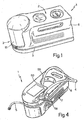
- Number 1 in Figures 1 to 4 indicates as a whole a kit for fast repair of inflatable articles, in particular, tyres.
- Kit 1 substantially comprises an electric compressor assembly 2; a container 3 of sealing liquid; a first hose 4 connecting container 3 to compressor assembly 2; and a second hose 5 connecting container 3 to a valve (not shown) of the tyre.
- compressor assembly 2 comprises an electric motor and a compressor - powered by the electric motor - which are housed inside an outer casing 6.
- Casing 6 is substantially parallelepiped-shaped and, atone longitudinal end, defines a seat 7 for housing container 3 upside down. More specifically, seat 7 is bounded laterally by a substantially semicylindrical end wall 10 of casing 6, and at the bottom by a circular base 14 projecting from end wall 10.
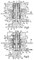
- Container 3 comprises a vessel 15, preferably in the form of a bottle, containing the sealing liquid and having an externally threaded neck 16 defining an opening 17 ( Figures 5 and 6 ); and a valve device 18 housed in opening 17.
- Valve device 18 forms an integral part of container 3, to ensure the container is closed fluidtight when detached from the rest of kit 1, as explained in detail below.
- Valve device 18 comprises a body 19 having a cylindrical lateral wall 20, of axis A, inserted in fluidtight manner inside neck 16, and a portion 20a of which extends beyond neck 16, into vessel 15, and is closed at one end by an end wall 21.
- Portion 20a has two circumferential series of holes 24, 25 communicating with the inside of vessel 15, spaced axially apart, and located close to end wall 21 and close to neck 16 respectively.
- Body 19 of valve device 18 also comprises an inner member 26 defined by a tubular rod 27 of axis A, and by a supporting ring 28 fixed inside an open end of body 19 and connected integrally to tubular rod 27 by a number of spokes 29 forming a numberof axial passages 29a.
- Rod 27 has a first end portion 27a close to end wall 21, and a conveniently flanged second end portion 27b projecting axially outwards of body 19, and defines internally an axial passage 27c.
- Valve device 18 comprises a tubular slide 30, which slides axially inside the annular chamber 36 formed between body 19 and rod 27.
- Slide 30 is maintained in an axial stop position against end wall 21 by a helical spring 31 compressed axially between slide 30 and supporting ring 28.
- Slide 30 has a circumferential series of holes 32 formed at an outer annular groove 33 dividing the slide into two portions 37, 38.
- Slide 30 also comprises two pairs of outer, axially spaced sealing rings (O-rings) 34a, 34b and 35a, 35b, which are housed in respective annular seats and form a sliding seal between slide 30 and body 19.
- the two pairs of O-rings 34a, 34b and 35a, 35b are located on axially opposite sides of holes 32. More specifically, O-rings 34a, 34b are carried by portion 37facing end wall 21, and O-rings 35a, 35b are carried by portion 38 facing end portion 27b of rod 27.
- O-ring 34a is located between holes 24 and end wall 21; O-ring 34b is located between holes 24 and holes 32; O-ring 35a is located between holes 25 and holes 32; and O-ring 35b is located on the axially opposite side of holes 25 to O-ring 35a.
- Portion 37 of slide 30 slides in fluidtight manner on rod 27, preferably with the interposition of an O-ring 38a on rod 27.
- Portion 38 of slide 30 is larger in inside diameter than rod 27, and defines with rod 27 a chamber 39 open towards the flanged end portion 27b of rod 27 and communicating with holes 32.
- Kit 1 also comprises a dispenser unit 40, which is housed stably but detachably inside a recess 44 in base 14 of casing 6, and is connected detachably to container 3 to fit it, upside down, to casing 6 ( Figures 1 , 5 and 6 ).
- dispenser unit 40 substantially comprises a plug-like central portion 45 having a substantially cylindrical lateral wall 46 and an end wall 47, which define an internally threaded cavity 48 into which neck 16 of vessel 15 is screwed; and a circular flange 68 extending radially from central portion 45 and defining a bayonet connection with corresponding fastening means 49 in base 14 of casing 6.
- Dispenser unit 40 also comprises a first tubular fitting 50 projecting radially from central portion 45 and defining a conduit 51 communicating with and radial with respect to a bottom portion 52 of cavity 48; and a substantially pipe-like second tubularfitting 53 projecting radially, close to end wall 47 of central portion 45, in a radial direction perpendicular to that of first tubular fitting 50.
- Second tubular fitting 53 defines a conduit 54 communicating coaxially with bottom portion 52 of cavity 48.
- end portion 27b of tubular rod 27 - possibly fitted with an annular sealing member 69 on the end - cooperates in fluidtight manner with end wall 47 of central portion 45, so that the internal axial passage 27c of rod 27 communicates with and substantially constitutes an extension of conduit 54 ( Figures 5 and 6 ).
- Base 14 has lateral openings (one shown in Figure 4 ) through which fittings 50, 53 are accessible from outside casing 6, once dispenser unit 40 is bayonet connected inside recess 44 in base 14, e.g. by rotating it 45° with respect to the Figure 2 insertion position.
- First fitting 50 is connected to hose 5, which, when not in use, may be wound about the casing and housed inside a peripheral groove 56 in the casing; and second fitting 53 is connected to compressor 2 by hose 4.
- hose 4 is longer than required for connection to fitting 53, and is fitted on its free end with a fast-fit, e.g. lever-operated, coupling 58.
- Hose 4 is therefore normally connected to second fitting 53, but can be detached easily and connected directly to the article, e.g. a tyre, ball, dinghy, etc., if this simply needs inflating and not repair.
- Hose 4 is normally stowed almost entirely inside a seat 59 formed on the underside of casing 6, from which it extends along an underside groove 60 housing the end portion of hose 4 fitted with coupling 58.
- Second fitting 53 is located at a different height from first fitting 50, so as to avoid any interference with hose 5 wound about casing 6.
- Compressor assembly 2 has an electric power cable 61 fitted on the end with a connector 62 for connection to a current outlet on the vehicle. Cable 61 is normally housed in a seat 63 formed in a portion of casing 6 opposite seat 7 for container 3, and connector 62 is stowed inside a cavity 64 in seat 63. Compressor assembly 2 is conveniently provided with a gauge 65 and a switch 66.
- Kit 1 and particularly container 3 operate as follows.
- Kit 1 is an integrated preassembled unit, which is supplied ready for use as shown in Figure 1 .
- hose 5 is simply connected to the tyre valve, and compressor assembly 2 activated.
- Slide 30 therefore moves, in opposition to spring 31, from the Figure 5 rest position to the Figure 6 position, in which O-rings 34a, 34b are interposed between holes 24 and holes 25, and O-ring 35a has moved past holes 25, so that holes 32 in slide 30 communicate with holes 25.
- Compressed air therefore flows through holes 24 into container 3, which is therefore pressurized, so that sealing liquid flows through holes 25 and holes 32 into chamber 39 in slide 30, and is fed along fitting 50 and hose 5 to the tyre.
- Device 18 therefore acts as a two-way, two-position, pneumatic valve. In the closed position ( Figure 5 ), the container is sealed; with pressure along the feed line defined by hose 4, device 18 opens automatically to allow compressed air into container 3, and simultaneous outflow of sealing liquid.
- kit 1 according to the present invention.
- kit 1 is a compact, integrated unit that can be stowed ready for use, with no additional work required, other than connection to the vehicle electric system and to the tyre.
- Container 3 with an integrated valve device 18 constitutes an independent sealed unit, regardless of whether or not it is connected to dispenser unit 40.
- dispenser unit 40 need not be replaced, and may be left permanently inside casing 6.
- container 3 is ready for use at all times, i.e. fitted permanently to kit 1.
- Container 3 in fact, is sealed but operated immediately in response to turning on the compressor.
- Unit 40 is preferably detachable from casing 6 and carried by container 3.
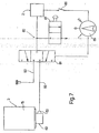
- Figure 7 shows a diagram of a pneumatic sealing liquid dispensing circuit 80 comprising a three-way, three-position valve 81, a conduit 82 connected to second fitting 53, and an additional hose 83 connectable to the tyre.
- Valve 81 is input connected to the compressor of compressor assembly 2, and is output connected to conduit 82 and additional hose 83.
- Valve 81 is controlled by a hand-operated selector 85 located on casing 6 and cooperating with an on-switch 86 of compressor assembly 2.
- selector 85 defines a disabling position, in which on-switch 86 is disabled and compressor assembly 2 can not be started, thus preventing it from being turned on accidentally; and a first and second enabling position, in which on-switch 86 is enabled to start the compressor. More specifically, in the first enabling position, valve 81 is switched automatically to connect the compressorto dispenser unit 40 via second fitting 53 and disconnect additional hopes 83; and, in the second enabling position, valve 81 is switched automatically to connect the compressor to additional hose 83 .and disconnect dispenser unit 40. Additional hose 83 is housed in casing 6, and enables compressor assembly 2 to be used quickly and easily to inflate a flat tyre.
- Pneumatic circuit 80 and hose 5 may also be connected to one or more hand-operated relief valves 87, to prevent overpressure in conduit 82 and hoses 5 and 83, or, when the compressor is off, to accurately adjust the pressure of the inflatable article as required.
- hose 5 connected to the tyre may be fitted with a non-return valve, to prevent sealing liquid leakage when hose 5 is detached from the tyre.
- Container 3 may also be connected to casing 6 by a click-on coupling acting in a direction parallel to axis A.
Landscapes
- Engineering & Computer Science (AREA)
- Mechanical Engineering (AREA)
- Pens And Brushes (AREA)
Claims (14)
- Ausrüstsatz zum Aufblasen und Reparieren aufblasbarer Artikel, insbesondere von Reifen,
wobei der Ausrüstsatz aufweist: eine Kompressoranordnung (2), einen Behälter (3) mit einer Versiegelungsflüssigkeit und erste Verbindungseinrichtungen (4, 5) zum Verbinden des Behälters mit der Kompressoranordnung (2) und mit einem aufblasbaren Artikel zum Reparieren und Aufblasen, ein äußeres Gehäuse (6), welches die Kompressoranordnung (2) aufnimmt und einen Sitz (7) für den Behälter mit der Versiegelungsflüssigkeit definiert, wobei der Behälter (3) entfernbar in dem Sitz (7) aufgenommen ist, und eine lösbare zweite Verbindungseinrichtung (4, 40) zum stabilen Verbinden des Behälters mit der Kompressoranordnung (2) derart, dass der Behälter (3), wenn er in dem Sitz (7) aufgenommen ist, funktional mit der Kompressoranordnung (2) verbunden bleibt, wobei die ersten Verbindungseinrichtungen (4, 5) eine dritte Verbindungseinrichtung in Form eines ersten Schlauches (4) oder einer Versorgungsleitung, die den Behälter (3) mit der Kompressoranordnung (2) verbindet, und eine vierte Verbindungseinrichtung in Form eines zweiten Schlauchs (5) aufweist, der mit dem Behälter (3) verbunden und mit einem Ventil des aufblasbaren Artikels verbindbar ist, um den aufblasbaren Artikel zu reparieren,
wobei der Ausrüstsatz dadurch gekennzeichnet ist, dass das äußere Gehäuse (6) den Sitz (7) definiert, und zwar lateral begrenzt durch eine im Wesentlichen halbzylinderförmige Endwand (10) des äußeren Gehäuses (6) und am Boden durch einen kreisförmigen Sockel (14), der aus der Endwand (10) hervorsteht und dadurch, dass das der Schlauch (5) der vierten Verbindungseinrichtung um das äußere Gehäuse (6) gewunden und innerhalb einer umlaufenden Vertiefung (56) des Gehäuses aufgenommen ist, wenn er nicht verwendet wird. - Ausrüstsatz nach Anspruch 1,
dadurch gekennzeichnet,
dass die Verbindungseinrichtungen eine Zuführleitung (4) für Druckluft zum Zuführen von Druckluft aus der Kompressoranordnung (2) zum Behälter (3) aufweisen und dass der Behälter (3) ein Gefäß (15) mit einer Öffnung (17) und einer Ventileinrichtung (18) aufweist, welche in einer fluiddichten Art und Weise in die Öffnung (17) eingepasst ist, einen Auslass (27c), welcher mit der Zuführleitung (4) für die Druckluft verbindbar ist, und einem Auslass (29a) für die Versiegelungsflüssigkeit aufweist. - Ausrüstsatz nach Anspruch 2,
dadurch gekennzeichnet,
dass die Ventileinrichtung (18) mindestens ein Steuerelement (30) aufweist, welches in Antwort auf ein Beaufschlagen der Zuführleitung (4) für die Druckluft mit Druck von einer geschlossenen Stellung, welche die Ventileinrichtung (18) schließt und in welcher der Einlass (27c) und der Auslass (29a) vom Inneren des Behälters (3) isoliert sind, zu einer offenen Stellung bewegbar ist, in welcher der Einlass (27c) und der Auslass (29a) mit dem Inneren des Behälters (3) in Verbindung stehen. - Ausrüstsatz nach Anspruch 3,
dadurch gekennzeichnet,
dass die Ventileinrichtung (18) ein elastisches Element (31) aufweist, um das Steuerelement (30) in stabiler Art und Weise in Abwesenheit eines Drucks auf den Einlass (27c) in der geschlossenen Stellung zu halten. - Ausrüstsatz nach einem der vorangehenden Ansprüche,
dadurch gekennzeichnet,
dass des Weiteren eine Ausgebereinheit (40) vorgesehen ist, welche lösbar mit dem Behälter (3) verbindbar ist und einen Einlassanschluss (53), der in fluiddichter Art und Weise mit dem Einlass (27c) der Ventileinrichtung (18) verbunden ist, und einen Auslassanschluss (50) aufweist, welcher in fluiddichter Art und Weise mit dem Auslass (29a) der Ventileinrichtung (18) verbunden ist. - Ausrüstsatz nach Anspruch 5,
dadurch gekennzeichnet,
dass die Ausgebereinheit (40) vom Gehäuse (6) lösbar ist. - Ausrüstsatz nach Anspruch 6,
dadurch gekennzeichnet,
dass der Sitz (7) einen Sockelbereich (14) mit einer Schnellbefestigungseinrichtung (49) aufweist, um die Ausgebereinheit (40) am Gehäuse (6) zu sichern. - Ausrüstsatz nach Anspruch 7,
dadurch gekennzeichnet,
dass die Befestigungseinrichtung (49) eine Bajonettverbindung aufweist. - Ausrüstsatz nach einem der Ansprüche 5 bis 8,
dadurch gekennzeichnet,
dass die Ausgebereinheit (40) eine Kavität (48) aufweist, mit welcher ein Halsbereich (16) des Behälters (3) in einer auf dem Kopf stehenden Anordnung eingepasst ist und dass der Halsbereich (16) die Öffnung (17) definiert. - Ausrüstsatz nach einem der vorangehenden Ansprüche,
dadurch gekennzeichnet,
dass des Weiteren vorgesehen sind ein zusätzlicher Schlauch (83), welcher mit dem aufblasbaren Artikel zusammenwirkt, und ein Dreiwegeventil (81), welche in Bezug auf den Eingang mit der Kompressoranordnung (2) und Bezug auf den Ausgang mit dem Behälter (3) und dem zusätzlichen Schlauch (83) verbunden ist, um einem Strom Druckluft selektiv zum Behälter (3) oder zum zusätzlichen Schlauch (83) zu führen. - Ausrüstsatz nach Anspruch 9,
dadurch gekennzeichnet,
dass das Dreiwegeventil (81) gesteuert wird durch eine Auswahleinrichtung (85), welche gesetzt werden kann in eine Sperrstellung, bei welcher der Betrieb der Kompressoranordnung (2) gesperrt ist, in eine erste Freigabestellung, bei welcher der Betrieb der Kompressoranordnung (2) freigegeben und der Behälter (3) fluidmäßig mit der Kompressoranordnung (2) verbunden ist, sowie in eine zweite Freigabestellung, bei welcher der Betrieb der Kompressoranordnung (2) freigegeben und der zusätzliche Schlauch (83) fluidmäßig mit der Kompressoranordnung (2) verbunden ist. - Ausrüstsatz nach einem der vorangehenden Ansprüche,
dadurch gekennzeichnet,
dass mindestens ein Element aus der Gruppe, die aufweist die Verbindungseinrichtung (4) und den zusätzlichen Schlauch (83), mit einem Entlastungsventil (87) verbunden ist. - Ausrüstsatz nach einem der vorangehenden Ansprüche,
dadurch gekennzeichnet,
dass die Verbindungseinrichtungen (5) ein Sperrventil aufweisen. - Ausrüstsatz nach Anspruch 7,
dadurch gekennzeichnet,
dass die Befestigungseinrichtung eine Schnellrastkupplung aufweist.
Priority Applications (4)
| Application Number | Priority Date | Filing Date | Title |
|---|---|---|---|
| EP09156222A EP2067674A1 (de) | 2004-02-27 | 2005-02-08 | Ausrüstungssatz zum Aufblasen und Reparieren aufblasbarer Artikel, insbesondere Reifen |
| EP10186079A EP2295299B1 (de) | 2004-02-27 | 2005-02-08 | Ausrüstungssatz zum Aufblasen und Reparieren aufblasbarer Artikel, insbesondere Reifen |
| DK08158282.7T DK1961632T3 (da) | 2004-02-27 | 2005-02-08 | Kit til oppustning og reparation af oppustelige genstande, især dæk |
| EP08158282A EP1961632B1 (de) | 2004-02-27 | 2005-02-08 | Ausrüstungssatz zum Aufblasen und Reparieren aufblasbarer Artikel, insbesondere Reifen |
Applications Claiming Priority (2)
| Application Number | Priority Date | Filing Date | Title |
|---|---|---|---|
| IT000117A ITTO20040117A1 (it) | 2004-02-27 | 2004-02-27 | Kit per il gonfiaggio e la riparazione di articoli gonfiabili, in particolare pneumatici |
| PCT/IB2005/000309 WO2005085028A1 (en) | 2004-02-27 | 2005-02-08 | Kit for inflating and repairing inflatable articles, in particular tyres |
Related Child Applications (5)
| Application Number | Title | Priority Date | Filing Date |
|---|---|---|---|
| EP09156222A Division EP2067674A1 (de) | 2004-02-27 | 2005-02-08 | Ausrüstungssatz zum Aufblasen und Reparieren aufblasbarer Artikel, insbesondere Reifen |
| EP09156222A Division-Into EP2067674A1 (de) | 2004-02-27 | 2005-02-08 | Ausrüstungssatz zum Aufblasen und Reparieren aufblasbarer Artikel, insbesondere Reifen |
| EP10186079A Division-Into EP2295299B1 (de) | 2004-02-27 | 2005-02-08 | Ausrüstungssatz zum Aufblasen und Reparieren aufblasbarer Artikel, insbesondere Reifen |
| EP08158282A Division EP1961632B1 (de) | 2004-02-27 | 2005-02-08 | Ausrüstungssatz zum Aufblasen und Reparieren aufblasbarer Artikel, insbesondere Reifen |
| EP08158282A Division-Into EP1961632B1 (de) | 2004-02-27 | 2005-02-08 | Ausrüstungssatz zum Aufblasen und Reparieren aufblasbarer Artikel, insbesondere Reifen |
Publications (3)
| Publication Number | Publication Date |
|---|---|
| EP1723016A1 EP1723016A1 (de) | 2006-11-22 |
| EP1723016B1 EP1723016B1 (de) | 2009-04-15 |
| EP1723016B2 true EP1723016B2 (de) | 2016-08-17 |
Family
ID=34917557
Family Applications (4)
| Application Number | Title | Priority Date | Filing Date |
|---|---|---|---|
| EP10186079A Expired - Lifetime EP2295299B1 (de) | 2004-02-27 | 2005-02-08 | Ausrüstungssatz zum Aufblasen und Reparieren aufblasbarer Artikel, insbesondere Reifen |
| EP08158282A Expired - Lifetime EP1961632B1 (de) | 2004-02-27 | 2005-02-08 | Ausrüstungssatz zum Aufblasen und Reparieren aufblasbarer Artikel, insbesondere Reifen |
| EP09156222A Withdrawn EP2067674A1 (de) | 2004-02-27 | 2005-02-08 | Ausrüstungssatz zum Aufblasen und Reparieren aufblasbarer Artikel, insbesondere Reifen |
| EP05702451.5A Expired - Lifetime EP1723016B2 (de) | 2004-02-27 | 2005-02-08 | Ausrüstungssatz zum aufblasen und reparieren aufblasbarer artikel, insbesondere reifen |
Family Applications Before (3)
| Application Number | Title | Priority Date | Filing Date |
|---|---|---|---|
| EP10186079A Expired - Lifetime EP2295299B1 (de) | 2004-02-27 | 2005-02-08 | Ausrüstungssatz zum Aufblasen und Reparieren aufblasbarer Artikel, insbesondere Reifen |
| EP08158282A Expired - Lifetime EP1961632B1 (de) | 2004-02-27 | 2005-02-08 | Ausrüstungssatz zum Aufblasen und Reparieren aufblasbarer Artikel, insbesondere Reifen |
| EP09156222A Withdrawn EP2067674A1 (de) | 2004-02-27 | 2005-02-08 | Ausrüstungssatz zum Aufblasen und Reparieren aufblasbarer Artikel, insbesondere Reifen |
Country Status (11)
| Country | Link |
|---|---|
| US (3) | US7789110B2 (de) |
| EP (4) | EP2295299B1 (de) |
| CN (3) | CN100575161C (de) |
| AT (2) | ATE465917T1 (de) |
| BR (1) | BRPI0508105A (de) |
| CA (1) | CA2557556A1 (de) |
| DE (3) | DE202005021981U1 (de) |
| DK (1) | DK1961632T3 (de) |
| ES (2) | ES2325547T3 (de) |
| IT (1) | ITTO20040117A1 (de) |
| WO (1) | WO2005085028A1 (de) |
Families Citing this family (84)
| Publication number | Priority date | Publication date | Assignee | Title |
|---|---|---|---|---|
| ITTO20040117A1 (it) * | 2004-02-27 | 2004-05-27 | Tek Srl | Kit per il gonfiaggio e la riparazione di articoli gonfiabili, in particolare pneumatici |
| DE202005017071U1 (de) * | 2005-10-28 | 2007-03-15 | Stehle, Michael | Einfüllsystem zum Abdichten und Aufpumpen von Reifen |
| ATE448074T1 (de) | 2006-02-07 | 2009-11-15 | Doukas Ag | Vorrichtung zum ausbringen von reifendichtmittel aus einem behälter |
| ITTO20060166A1 (it) * | 2006-03-07 | 2007-09-08 | Tek Srl | Kit automatico di riparazione e gonfiaggio per oggetti gonfiabili provvisto di una valvola selettrice |
| ITTO20060454A1 (it) * | 2006-06-20 | 2007-12-21 | Tek Srl | Kit per la riparazione e il gonfiaggio di articoli gonfiabili |
| JP4871106B2 (ja) * | 2006-06-20 | 2012-02-08 | 株式会社ブリヂストン | シーリング・ポンプアップ装置 |
| ITTO20060662A1 (it) * | 2006-09-18 | 2008-03-19 | Tek Srl | Kit per la riparazione e il gonfiaggio di articoli gonfiabili |
| US7798183B2 (en) * | 2006-10-26 | 2010-09-21 | Illinois Tool Works Inc. | Integrated compressor-tire sealant injection device with large mouth sealant container |
| JP5376754B2 (ja) * | 2006-12-21 | 2013-12-25 | 株式会社ブリヂストン | シーリング装置 |
| DE102007003667B4 (de) * | 2007-01-18 | 2016-12-29 | Continental Reifen Deutschland Gmbh | Vorrichtung zum Abdichten und Aufpumpen aufblasbarer Gegenstände |
| USD574866S1 (en) * | 2007-03-05 | 2008-08-12 | Bridgestone Corporation | Apparatus for repairing punctured tires |
| ITTO20070323A1 (it) | 2007-05-11 | 2008-11-12 | Tek Global Srl | Kit per la riparazione e il gonfiaggio di articoli gonfiabili e relativo metodo di controllo |
| US8146622B2 (en) * | 2007-08-20 | 2012-04-03 | Ford Global Technologies, Llc | Switch and hose-valve connection arrangement for vehicle temporary mobility kit |
| US8276624B2 (en) * | 2008-01-31 | 2012-10-02 | Ford Global Technologies, Llc | Sealant bottle snap-in feature for vehicle temporary mobility kit |
| US8115615B2 (en) * | 2007-09-08 | 2012-02-14 | Ford Global Technologies | Status indicator and reminder system for vehicle temporary mobility kit |
| US8517760B2 (en) | 2007-08-20 | 2013-08-27 | Ford Global Technologies, Llc | Cord wrap and power plug receptacle arrangement for inflator |
| ITTO20070610A1 (it) * | 2007-08-28 | 2009-02-28 | Tek Global Srl | Gruppo contenitore di liquido sigillante e kit per la riparazione e il gonfiaggio di articoli gonfiabili provvisto di un tale contenitore |
| US8981921B2 (en) | 2007-09-08 | 2015-03-17 | Ford Global Technologies, Llc | Status indicator and reminder system for vehicle temporary mobility kit |
| ITTO20070776A1 (it) † | 2007-10-31 | 2009-05-01 | Tek Global Srl | Kit per la riparazione e il gonfiaggio di articoli gonfiabili provvisto di un dispositivo di controllo |
| ES2701157T3 (es) * | 2007-11-27 | 2019-02-21 | Uppsala Univ Projekt Ab | Materiales compuestos que incluyen un polímero intrínsecamente conductor, y métodos y dispositivos |
| USD613320S1 (en) * | 2007-11-28 | 2010-04-06 | Tek Global S.R.L. | Fitting for tire inflation and tire repair |
| USD611076S1 (en) * | 2008-03-06 | 2010-03-02 | Bridgestone Corporation | Apparatus for repairing punctured tires |
| CN101977755A (zh) * | 2008-03-25 | 2011-02-16 | 住友橡胶工业株式会社 | 轮胎穿孔修补装置 |
| DE102008025571A1 (de) * | 2008-05-28 | 2009-12-03 | Doukas Ag | Kompressoreinheit, insbesondere für Geländefahrzeuge |
| DE102008027024A1 (de) * | 2008-06-06 | 2009-12-10 | Sumitomo Rubber Industries Ltd., Kobe | Vorrichtung zum Einbringen von Luft und/oder Abdichtmittel in einen Reifen |
| USD599389S1 (en) * | 2008-06-06 | 2009-09-01 | Sumitomo Rubber Industries, Ltd. | Tire sealing and inflation device |
| ITTO20080493A1 (it) * | 2008-06-23 | 2009-12-24 | Tek Global Srl | Kit per la riparazione e il gonfiaggio di articoli gonfiabili provvisto di un manometro perfezionato e relativo metodo |
| USD597574S1 (en) * | 2008-07-16 | 2009-08-04 | Continental Aktiengesellschaft | Repair unit for pneumatic tires |
| DE102008033477B4 (de) * | 2008-07-16 | 2019-02-21 | Sumitomo Rubber Industries, Ltd. | Vorrichtung zum Einbringen von Luft und/oder Abdichtmittel in einen Reifen |
| US8020588B2 (en) * | 2008-09-11 | 2011-09-20 | Min-Hsieng Wang | Tire repair solution can |
| JP4766093B2 (ja) * | 2008-09-22 | 2011-09-07 | 横浜ゴム株式会社 | パンク補修液収容容器 |
| JP4793418B2 (ja) * | 2008-09-22 | 2011-10-12 | 横浜ゴム株式会社 | パンク補修液収容容器 |
| US8413692B1 (en) * | 2008-10-07 | 2013-04-09 | Illinois Tool Works, Inc. | Sealant dispenser apparatus and method |
| US20100108185A1 (en) * | 2008-11-04 | 2010-05-06 | Wen San Chou | Air compressor and tire repairing combination |
| US8522833B2 (en) * | 2008-11-04 | 2013-09-03 | Wen San Chou | Device for sealing and inflating inflatable object |
| IT1391874B1 (it) * | 2008-11-13 | 2012-01-27 | Tek Global Srl | Kit per la riparazione e il gonfiaggio di articoli gonfiabili provvisto di una valvola di selezione |
| CN102317061B (zh) * | 2009-02-11 | 2014-06-18 | Tek环球有限公司 | 用于修补和充气可充气物件的单元 |
| IT1395645B1 (it) * | 2009-05-27 | 2012-10-16 | Tek Global Srl | Gruppo per la riparazione e il gonfiaggio di un articolo gonfiabile |
| IT1394941B1 (it) * | 2009-02-11 | 2012-07-27 | Tek Global Srl | Gruppo per la riparazione e il gonfiaggio di un articolo gonfiabile |
| IT1393770B1 (it) * | 2009-02-11 | 2012-05-08 | Tek Global Srl | Gruppo per la riparazione e il gonfiaggio di un articolo gonfiabile |
| USD647119S1 (en) * | 2009-06-30 | 2011-10-18 | Active Tools International (Hk) Ltd. | Inflator and flat tire repair machine |
| IT1395661B1 (it) * | 2009-08-21 | 2012-10-16 | Tek Global Srl | Contenitore per un liquido sigillante e kit di riparazione comprendente tale contenitore |
| DE102009060272B4 (de) * | 2009-12-23 | 2022-11-10 | Sumitomo Rubber Industries Ltd. | Vorrichtung zum Einbringen von Luft und/oder Abdichtmittel in einen Reifen |
| EP2399728B1 (de) * | 2010-06-28 | 2015-02-25 | Wen-San Jhou | Vorrichtung zum Versiegeln und Aufpumpen eines aufpumpbaren Objekts |
| US8925594B2 (en) * | 2011-01-04 | 2015-01-06 | Bell Automotive Products, Inc. | Portable tire inflator and reflective device |
| US8887769B1 (en) * | 2011-01-04 | 2014-11-18 | Bell Automotive Products, Inc. | Rechargeable tire inflator with adaptable hose holder |
| CN102673531B (zh) * | 2011-03-14 | 2017-01-25 | 胎意科汽车配件(上海)有限公司 | 使用改进的分流阀的对可充气物品进行修理和充气的设备 |
| CN102673532B (zh) * | 2011-03-14 | 2016-08-03 | 胎意科汽车配件(上海)有限公司 | 用于对可充气物品进行修理和充气的具有改进的阀的密封剂容器单元 |
| US9073269B2 (en) | 2011-07-12 | 2015-07-07 | Plews, Inc. | Tire sealant delivery system |
| CN102896787B (zh) * | 2011-07-26 | 2016-04-27 | 胎意科汽车配件(上海)有限公司 | 具有降压装置的可充气物件修补和充气装备 |
| US8746293B2 (en) * | 2011-10-12 | 2014-06-10 | Wen San Chou | Device for sealing and inflating inflatable object |
| DE102012100636A1 (de) | 2012-01-26 | 2013-08-01 | Continental Reifen Deutschland Gmbh | Rückflusssicherung |
| TWM444270U (zh) * | 2012-04-16 | 2013-01-01 | 冠翔(香港)工業有限公司 | 氣體與膠料的整合供應裝置(二) |
| TWI490132B (zh) * | 2012-04-27 | 2015-07-01 | 周文三 | 車載用空氣壓縮機之串接軟管的接頭結構 |
| AU2012101671B4 (en) * | 2012-11-12 | 2013-10-31 | Active Tools International (Hk) Ltd. | Air Compressor |
| US9302654B2 (en) * | 2013-01-25 | 2016-04-05 | Illinois Tool Works Inc. | Device for dispensing tire sealant |
| US20160195078A1 (en) * | 2013-09-24 | 2016-07-07 | Illinois Tool Works Inc. | Compressor |
| EP3950289B1 (de) * | 2013-11-28 | 2025-01-01 | Sumitomo Rubber Industries, Ltd. | Selbstverschliessende schraubkupplung für schläuche. |
| DE102013113618A1 (de) * | 2013-12-06 | 2015-06-11 | Sumitomo Rubber Industries, Ltd. | Vorrichtung zum Einbringen von Druckluft und/oder Abdichtmittel in einen Reifen |
| DE102014205071A1 (de) * | 2014-03-19 | 2015-09-24 | Continental Reifen Deutschland Gmbh | Vorrichtung zum Abdichten und Aufpumpen aufblasbarer Gegenstände |
| EP3123589A1 (de) * | 2014-03-25 | 2017-02-01 | TEK GLOBAL S.r.l. | Vorrichtung und verfahren zum aufladen von batterien |
| GB2523608B (en) * | 2014-07-18 | 2018-09-05 | Holt Lloyd International Ltd | Product delivery device including an in-line pressure gauge |
| JP5867637B1 (ja) * | 2015-02-23 | 2016-02-24 | 横浜ゴム株式会社 | パンク修理液収容容器 |
| DE102015203972A1 (de) * | 2015-03-05 | 2016-09-08 | Continental Reifen Deutschland Gmbh | Tragbarer Reparatursatz |
| TWI647129B (zh) * | 2015-04-23 | 2019-01-11 | 周文三 | 空氣壓縮機裝置 |
| KR102330046B1 (ko) | 2015-09-02 | 2021-11-23 | 액티브 툴스 인터내셔널 (에이치케이) 리미티드. | 공기 팽창 디바이스 및 이의 제조 방법 |
| JP6862141B2 (ja) | 2015-10-14 | 2021-04-21 | エルジー イノテック カンパニー リミテッド | 発光素子パッケージ及び照明装置 |
| DE102015119917A1 (de) | 2015-11-18 | 2017-05-18 | Illinois Tool Works Inc. | Verfahren und Vorrichtung zum Ausbringen eines Mittels zum Abdichten eines aufblasbaren Gegenstandes |
| JP6620000B2 (ja) * | 2015-12-08 | 2019-12-11 | 株式会社ブリヂストン | パンク修理キット |
| AU2017220380B2 (en) | 2016-02-17 | 2021-02-25 | Trydel Research Pty Ltd | Improved apparatus for sealing and inflation of damaged inflatable articles, such as punctured tires |
| ITUA20164201A1 (it) * | 2016-06-08 | 2017-12-08 | Tek Global Srl | Contenitore sensorizzato di liquido sigillante e kit di riparazione per articoli gonfiabili con tale contenitore |
| USD842354S1 (en) * | 2016-07-05 | 2019-03-05 | Tek Global S.R.L. | Tire sealing and inflation device |
| AT519376B1 (de) * | 2016-11-21 | 2018-08-15 | Georg Hagleitner Hans | In eine Behälteröffnung einsetzbares Verschlusselement |
| JP6880903B2 (ja) * | 2017-03-27 | 2021-06-02 | 横浜ゴム株式会社 | パンク修理液の有効期限通知装置及び方法 |
| US10011082B1 (en) | 2017-03-31 | 2018-07-03 | Plews, Inc. | Pneumatic tire repair and inflation device |
| USD873863S1 (en) * | 2017-06-28 | 2020-01-28 | Tek Global S.R.L. | Tire sealing and inflation device |
| USD914769S1 (en) * | 2018-11-30 | 2021-03-30 | Tek Global S.R.L. | Tire sealing and inflation device |
| DE102021101463A1 (de) * | 2021-01-25 | 2022-07-28 | Illinois Tool Works Inc. | Reifenreparaturset und verfahren zum aufblasen und/oder abdichten eines reifens |
| US11794426B2 (en) | 2021-06-30 | 2023-10-24 | Illinois Tool Works Inc. | Flat tire repair device |
| JP7815696B2 (ja) * | 2021-11-09 | 2026-02-18 | 住友ゴム工業株式会社 | ボトルユニット及びパンク修理キット |
| US12502854B2 (en) * | 2022-09-27 | 2025-12-23 | Illinois Tool Works Inc. | Tire repair system |
| USD1066212S1 (en) | 2022-09-30 | 2025-03-11 | Illinois Tool Works Inc. | Tire repair system |
| USD1065007S1 (en) | 2022-09-30 | 2025-03-04 | Illinois Tool Works Inc. | Tire repair system |
| KR102743339B1 (ko) | 2022-12-08 | 2024-12-17 | 케이티 프로젝텐트윅렁스-게엠베하 | 차량 휠에 부착하기 위한 타이어 수리 장치 |
Citations (1)
| Publication number | Priority date | Publication date | Assignee | Title |
|---|---|---|---|---|
| WO2003041949A1 (en) † | 2001-11-15 | 2003-05-22 | Active Tools A/S | A device for sealing and inflating an inflatable object |
Family Cites Families (70)
| Publication number | Priority date | Publication date | Assignee | Title |
|---|---|---|---|---|
| US2812783A (en) | 1954-10-28 | 1957-11-12 | Quentin C Bufogle | Device for injecting chemicals into vehicle tires and the like |
| US3515181A (en) * | 1967-09-05 | 1970-06-02 | Lawrence R Sperberg | Means for transferring chemical into a pneumatic tire |
| US3729033A (en) | 1971-03-22 | 1973-04-24 | Af Scheppman And Son Mfg Co | Compact portable tire servicing device |
| US4104494A (en) | 1974-11-25 | 1978-08-01 | David Allen Swann | Electric switches |
| US4137206A (en) | 1977-02-14 | 1979-01-30 | New World Products, Inc. | Tire protection composition |
| US4426468A (en) | 1978-10-10 | 1984-01-17 | Rockcor, Inc. | Sealant composition |
| US4224208A (en) | 1979-01-22 | 1980-09-23 | New World Products, Inc. | Tire protection composition |
| US4276898A (en) | 1980-01-30 | 1981-07-07 | Stop-A-Flat Corporation | Delivery system for pneumatic vessels |
| US4308776A (en) | 1980-04-23 | 1982-01-05 | Philip Morris Incorporated | Web sectioning apparatus with adjustable knife engagement |
| US4317206A (en) | 1980-05-12 | 1982-02-23 | Rca Corporation | On line quality monitoring |
| US4337332A (en) | 1981-04-09 | 1982-06-29 | Minnesota Mining And Manufacturing Company | Latently curable organosilicone compositions |
| US4528331A (en) | 1981-05-07 | 1985-07-09 | The Firestone Tire & Rubber Company | Sealant compositions having, as an essential component, hydrogenated polybutadiene as network polymer |
| USD275291S (en) | 1982-09-13 | 1984-08-28 | M-D & Co. | Portable air compressor |
| US4498515A (en) | 1983-10-03 | 1985-02-12 | Eaton Corporation | Onboard tire inflation system |
| US4501825A (en) | 1984-06-28 | 1985-02-26 | Pennzoil Company | Tire sealer and inflator |
| USD295754S (en) | 1985-01-12 | 1988-05-17 | Ta-Chin Wang | Air compressor for tire inflation |
| US4713114A (en) | 1985-08-12 | 1987-12-15 | Smith Gerald P | Tire sealing and balancing composition |
| USD298832S (en) | 1986-04-10 | 1988-12-06 | M-D & Co. | Portable air compressor |
| US4765367A (en) * | 1986-07-03 | 1988-08-23 | Scott Mark E | Valve assembly |
| US4798233A (en) | 1987-03-02 | 1989-01-17 | Mooney Brian J | Portable compressed air delivery unit for tires with built-in antifreeze capability |
| US5251877A (en) * | 1988-03-18 | 1993-10-12 | Sparton Corporation | Sheave plate and cable assembly for a tire lift/carrier winch |
| US5070917A (en) * | 1989-06-14 | 1991-12-10 | Ferris James E | Pressurized fluid-drivable device for injecting a treatment liquid stored therein into a tire or other enclosed space |
| US4970242A (en) * | 1989-08-18 | 1990-11-13 | Nationwide Industries, Inc. | Anhydrous, nonflammable tire sealer and inflator |
| US5124395B1 (en) | 1991-04-25 | 1999-06-22 | Radiator Specialty Company | Non-ozone depleting non-flammable tire sealer and inflator composition |
| CA2129961A1 (en) | 1992-02-14 | 1993-08-19 | Phil Peelor | Tire sealant and inflator |
| US5648406A (en) | 1992-02-14 | 1997-07-15 | Specialty Chemical Resources, Inc. | Tire sealant and inflator |
| US5251787A (en) | 1992-03-09 | 1993-10-12 | Simson Anton K | Pressurized container dispenser |
| US5364463A (en) | 1992-06-02 | 1994-11-15 | Hull Jack L | Tire ballast and sealant |
| CN2130727Y (zh) * | 1992-08-04 | 1993-04-28 | 金杯通用汽车有限公司 | 轮胎充气机 |
| US5386857A (en) | 1993-03-30 | 1995-02-07 | International Marketing, Inc. | Method of and apparatus for introducing pulverulent material into a tire |
| US5403417A (en) * | 1993-07-22 | 1995-04-04 | Technical Chemical Company | Tire sealing methods and related apparatus |
| US5500456A (en) | 1994-01-26 | 1996-03-19 | Snap Products, Inc. | Tire sealer and inflator |
| US5765601A (en) | 1994-05-17 | 1998-06-16 | Radiator Specialty Company | Tire inflator and sealant product |
| US5618912A (en) | 1995-05-04 | 1997-04-08 | Pennzoil Products Company | Tire sealer and inflator compositions |
| DE19549592C5 (de) * | 1995-07-11 | 2006-12-14 | Sumitomo Rubber Industries Ltd., Kobe | Vorrichtung zum Abdichten und Aufpumpen von Reifen bei Pannen |
| US6176285B1 (en) * | 1996-12-17 | 2001-01-23 | Sumitomo Rubber Industries, Ltd. | Preparation for the sealing of tires with punctures, apparatus for the sealing and pumping up of tires and tires with an integrated sealing preparation |
| US5887762A (en) | 1997-08-06 | 1999-03-30 | Bobrick Washroom Equipment, Inc. | Replaceable valve system |
| DE29716453U1 (de) * | 1997-09-12 | 1999-01-21 | Alusuisse Bayrisches Druckguß-Werk GmbH & Co. KG, 85570 Markt Schwaben | Reparatursatz zum Reifenflicken |
| US5908145A (en) * | 1997-11-17 | 1999-06-01 | Jaksa; Martin E. | Pneumatic tire sealant dispenser |
| DE19846451C5 (de) * | 1998-10-08 | 2018-08-23 | Sumitomo Rubber Industries Ltd. | Vorrichtung zum Abdichten aufblasbarer Gegenstände, insbesondere Reifen |
| FR2789942A1 (fr) * | 1999-02-19 | 2000-08-25 | Michelin Soc Tech | Procede de gonflage d'une enveloppe de pneumatique et dispositif pour la mise en oeuvre de ce procede |
| DE10015166A1 (de) * | 2000-03-27 | 2001-10-04 | Dunlop Gmbh | Abdichtvorrichtung |
| US6412524B1 (en) * | 2000-11-17 | 2002-07-02 | International Marketing, Inc. | Apparatus for introducing flowable force compensating material into a tire |
| US20020112777A1 (en) | 2000-12-15 | 2002-08-22 | Pennzoil-Quaker State Company | Method and apparatus for inflating objects |
| DE20122862U1 (de) | 2001-02-13 | 2008-09-11 | Doukas Ag | Vorrichtung zum Ausbringen von Reifendichtmittel |
| CZ20022938A3 (cs) * | 2001-02-16 | 2003-02-12 | Continental Ag | Způsob plnění předmětu a zařízení k jeho provádění |
| US6345650B1 (en) * | 2001-05-22 | 2002-02-12 | Robert W. Paasch | Tire repair device and method |
| EP1401689A1 (de) * | 2001-07-02 | 2004-03-31 | Active Tools A/S | Aufblaseinheit mit dichtungsmerkmalen für einen mit luft gefüllten reifen |
| DE20113129U1 (de) | 2001-08-14 | 2002-12-19 | Thurner, Helmut, 94086 Bad Griesbach | Behälter für eine Reifenflickflüssigkeit in einem Reifenflicksatz |
| DE20115003U1 (de) * | 2001-09-11 | 2003-02-06 | Dunlop GmbH, 63450 Hanau | Abdichtsystem |
| US6789581B2 (en) * | 2002-10-31 | 2004-09-14 | Interdynamics, Inc. | Apparatus for sealing, inflating, and repairing tires |
| WO2004086094A1 (en) | 2003-03-26 | 2004-10-07 | Westergeco Seismic Holdings Limited | Processing seismic data representative of the acceleration wavefield |
| JP4210149B2 (ja) | 2003-05-14 | 2009-01-14 | 株式会社ブリヂストン | タイヤのシーリング・ポンプアップ装置及びポンプアップ装置 |
| CN1330508C (zh) * | 2003-08-13 | 2007-08-08 | 刘少怀 | 便携式摩托车充气装置 |
| ITTO20040121A1 (it) * | 2004-02-27 | 2004-05-27 | Tek Srl | Contenitore per un liquido sigillante per la riparazione di oggetti gonfiabili, in particolare pnematici, e kit di riparazione provvisto di tale contenitore |
| ITTO20040117A1 (it) * | 2004-02-27 | 2004-05-27 | Tek Srl | Kit per il gonfiaggio e la riparazione di articoli gonfiabili, in particolare pneumatici |
| CN1960850B (zh) * | 2004-05-27 | 2010-12-08 | 株式会社普利司通 | 密封打气装置 |
| JP4133945B2 (ja) * | 2004-06-28 | 2008-08-13 | 住友ゴム工業株式会社 | タイヤのパンクシーリング剤送給、抜取り装置 |
| DE102004048002B3 (de) * | 2004-10-01 | 2005-10-06 | Arne Kant | Abdichtvorrichtung |
| US7389800B2 (en) | 2005-03-25 | 2008-06-24 | Accessories Marketing, Inc. | Orientation-independent fluid delivery apparatus |
| JP4673134B2 (ja) * | 2005-06-02 | 2011-04-20 | 株式会社ブリヂストン | シーリング剤の保管・注入容器 |
| ATE448074T1 (de) * | 2006-02-07 | 2009-11-15 | Doukas Ag | Vorrichtung zum ausbringen von reifendichtmittel aus einem behälter |
| ITTO20060166A1 (it) * | 2006-03-07 | 2007-09-08 | Tek Srl | Kit automatico di riparazione e gonfiaggio per oggetti gonfiabili provvisto di una valvola selettrice |
| US7798183B2 (en) | 2006-10-26 | 2010-09-21 | Illinois Tool Works Inc. | Integrated compressor-tire sealant injection device with large mouth sealant container |
| ITTO20070591A1 (it) * | 2007-08-08 | 2009-02-09 | Tek Global Srl | Kit per la riparazione e il gonfiaggio di articoli gonfiabili provvisto di un dispositivo di controllo e relativo gruppo contenitore |
| US8146622B2 (en) * | 2007-08-20 | 2012-04-03 | Ford Global Technologies, Llc | Switch and hose-valve connection arrangement for vehicle temporary mobility kit |
| USD583206S1 (en) * | 2007-10-29 | 2008-12-23 | Trans Tech Products, Llc | Dispensing head for a tire sealing apparatus |
| US20090107578A1 (en) * | 2007-10-29 | 2009-04-30 | Saul Trachtenberg | Tire sealant dispensing apparatus |
| CN102317061B (zh) * | 2009-02-11 | 2014-06-18 | Tek环球有限公司 | 用于修补和充气可充气物件的单元 |
| DE102009060272B4 (de) * | 2009-12-23 | 2022-11-10 | Sumitomo Rubber Industries Ltd. | Vorrichtung zum Einbringen von Luft und/oder Abdichtmittel in einen Reifen |
-
2004
- 2004-02-27 IT IT000117A patent/ITTO20040117A1/it unknown
-
2005
- 2005-02-08 AT AT08158282T patent/ATE465917T1/de not_active IP Right Cessation
- 2005-02-08 EP EP10186079A patent/EP2295299B1/de not_active Expired - Lifetime
- 2005-02-08 CA CA002557556A patent/CA2557556A1/en not_active Abandoned
- 2005-02-08 CN CN200580006182A patent/CN100575161C/zh not_active Expired - Fee Related
- 2005-02-08 EP EP08158282A patent/EP1961632B1/de not_active Expired - Lifetime
- 2005-02-08 AT AT05702451T patent/ATE428612T1/de not_active IP Right Cessation
- 2005-02-08 WO PCT/IB2005/000309 patent/WO2005085028A1/en not_active Ceased
- 2005-02-08 ES ES05702451T patent/ES2325547T3/es not_active Expired - Lifetime
- 2005-02-08 DK DK08158282.7T patent/DK1961632T3/da active
- 2005-02-08 EP EP09156222A patent/EP2067674A1/de not_active Withdrawn
- 2005-02-08 ES ES10186079T patent/ES2391349T3/es not_active Expired - Lifetime
- 2005-02-08 EP EP05702451.5A patent/EP1723016B2/de not_active Expired - Lifetime
- 2005-02-08 DE DE202005021981U patent/DE202005021981U1/de not_active Expired - Lifetime
- 2005-02-08 DE DE602005013928T patent/DE602005013928D1/de not_active Expired - Lifetime
- 2005-02-08 CN CN2009102064261A patent/CN101791975B/zh not_active Expired - Fee Related
- 2005-02-08 DE DE602005020992T patent/DE602005020992D1/de not_active Expired - Lifetime
- 2005-02-08 US US10/591,033 patent/US7789110B2/en active Active
- 2005-02-08 BR BRPI0508105-0A patent/BRPI0508105A/pt not_active IP Right Cessation
- 2005-02-08 CN CN2009102064276A patent/CN101786445B/zh not_active Expired - Fee Related
-
2010
- 2010-07-29 US US12/845,897 patent/US8752595B2/en not_active Expired - Lifetime
-
2013
- 2013-12-19 US US14/133,984 patent/US9573326B2/en not_active Expired - Fee Related
Patent Citations (1)
| Publication number | Priority date | Publication date | Assignee | Title |
|---|---|---|---|---|
| WO2003041949A1 (en) † | 2001-11-15 | 2003-05-22 | Active Tools A/S | A device for sealing and inflating an inflatable object |
Also Published As
| Publication number | Publication date |
|---|---|
| ES2325547T3 (es) | 2009-09-08 |
| EP1723016A1 (de) | 2006-11-22 |
| EP2295299B1 (de) | 2012-07-04 |
| DE602005013928D1 (de) | 2009-05-28 |
| CN101786445B (zh) | 2013-01-30 |
| ES2391349T3 (es) | 2012-11-23 |
| CN101791975B (zh) | 2013-01-02 |
| US9573326B2 (en) | 2017-02-21 |
| CN101791975A (zh) | 2010-08-04 |
| EP1723016B1 (de) | 2009-04-15 |
| BRPI0508105A (pt) | 2007-07-17 |
| CN1926018A (zh) | 2007-03-07 |
| DE602005020992D1 (de) | 2010-06-10 |
| ATE465917T1 (de) | 2010-05-15 |
| EP1961632B1 (de) | 2010-04-28 |
| DK1961632T3 (da) | 2010-08-23 |
| CA2557556A1 (en) | 2005-09-15 |
| US20110155279A1 (en) | 2011-06-30 |
| ATE428612T1 (de) | 2009-05-15 |
| EP2067674A1 (de) | 2009-06-10 |
| CN100575161C (zh) | 2009-12-30 |
| US20080029181A1 (en) | 2008-02-07 |
| CN101786445A (zh) | 2010-07-28 |
| US8752595B2 (en) | 2014-06-17 |
| ITTO20040117A1 (it) | 2004-05-27 |
| DE202005021981U1 (de) | 2012-03-23 |
| WO2005085028A1 (en) | 2005-09-15 |
| US7789110B2 (en) | 2010-09-07 |
| EP1961632A1 (de) | 2008-08-27 |
| EP2295299A1 (de) | 2011-03-16 |
| US20140373971A1 (en) | 2014-12-25 |
Similar Documents
| Publication | Publication Date | Title |
|---|---|---|
| EP1723016B1 (de) | Ausrüstungssatz zum aufblasen und reparieren aufblasbarer artikel, insbesondere reifen | |
| EP1722961B1 (de) | Behälter für abdichtungsflüssigkeit zur reparatur von aufblasbaren artikeln, insbesondere reifen und solch einen behälter enthaltender reparatursatz | |
| EP2286984B1 (de) | Dichtflüssigkeitsbehälter und reparatursatz mit dem behälter | |
| US8251106B2 (en) | Unit for repairing and inflating an inflatable article, vehicle comprising a unit for repairing and inflating inflatable articles, and relative method | |
| AU2012267894C1 (en) | System and method using a pressure reduction valve | |
| CN108349176B (zh) | 用于施加密封可充气制品的构件的方法和设备 | |
| CN101848803B (zh) | 具有阀单元并用于对可吹胀物体进行密封和充气的装置 | |
| US20100206426A1 (en) | Unit for repairing and inflating inflatable articles | |
| JP2015508349A (ja) | 逆流防止装置 | |
| US20120042987A1 (en) | Unit for repairing and inflating inflatable articles | |
| JP3180503U (ja) | 弁装置 | |
| CN118871284A (zh) | 用于根据需要对可充气物品或产品、特别是轮胎、优选地车辆轮胎进行充气或修理的装置 |
Legal Events
| Date | Code | Title | Description |
|---|---|---|---|
| PUAI | Public reference made under article 153(3) epc to a published international application that has entered the european phase |
Free format text: ORIGINAL CODE: 0009012 |
|
| 17P | Request for examination filed |
Effective date: 20060927 |
|
| AK | Designated contracting states |
Kind code of ref document: A1 Designated state(s): AT BE BG CH CY CZ DE DK EE ES FI FR GB GR HU IE IS IT LI LT LU MC NL PL PT RO SE SI SK TR |
|
| 17Q | First examination report despatched |
Effective date: 20070213 |
|
| DAX | Request for extension of the european patent (deleted) | ||
| RAP1 | Party data changed (applicant data changed or rights of an application transferred) |
Owner name: TEK GLOBAL S.R.L. |
|
| GRAP | Despatch of communication of intention to grant a patent |
Free format text: ORIGINAL CODE: EPIDOSNIGR1 |
|
| GRAP | Despatch of communication of intention to grant a patent |
Free format text: ORIGINAL CODE: EPIDOSNIGR1 |
|
| GRAS | Grant fee paid |
Free format text: ORIGINAL CODE: EPIDOSNIGR3 |
|
| GRAA | (expected) grant |
Free format text: ORIGINAL CODE: 0009210 |
|
| AK | Designated contracting states |
Kind code of ref document: B1 Designated state(s): AT BE BG CH CY CZ DE DK EE ES FI FR GB GR HU IE IS IT LI LT LU MC NL PL PT RO SE SI SK TR |
|
| REG | Reference to a national code |
Ref country code: CH Ref legal event code: EP Ref country code: GB Ref legal event code: FG4D |
|
| REG | Reference to a national code |
Ref country code: IE Ref legal event code: FG4D |
|
| REF | Corresponds to: |
Ref document number: 602005013928 Country of ref document: DE Date of ref document: 20090528 Kind code of ref document: P |
|
| REG | Reference to a national code |
Ref country code: ES Ref legal event code: FG2A Ref document number: 2325547 Country of ref document: ES Kind code of ref document: T3 |
|
| NLV1 | Nl: lapsed or annulled due to failure to fulfill the requirements of art. 29p and 29m of the patents act | ||
| PG25 | Lapsed in a contracting state [announced via postgrant information from national office to epo] |
Ref country code: LT Free format text: LAPSE BECAUSE OF FAILURE TO SUBMIT A TRANSLATION OF THE DESCRIPTION OR TO PAY THE FEE WITHIN THE PRESCRIBED TIME-LIMIT Effective date: 20090415 Ref country code: AT Free format text: LAPSE BECAUSE OF FAILURE TO SUBMIT A TRANSLATION OF THE DESCRIPTION OR TO PAY THE FEE WITHIN THE PRESCRIBED TIME-LIMIT Effective date: 20090415 Ref country code: FI Free format text: LAPSE BECAUSE OF FAILURE TO SUBMIT A TRANSLATION OF THE DESCRIPTION OR TO PAY THE FEE WITHIN THE PRESCRIBED TIME-LIMIT Effective date: 20090415 Ref country code: PT Free format text: LAPSE BECAUSE OF FAILURE TO SUBMIT A TRANSLATION OF THE DESCRIPTION OR TO PAY THE FEE WITHIN THE PRESCRIBED TIME-LIMIT Effective date: 20090915 |
|
| PG25 | Lapsed in a contracting state [announced via postgrant information from national office to epo] |
Ref country code: SE Free format text: LAPSE BECAUSE OF FAILURE TO SUBMIT A TRANSLATION OF THE DESCRIPTION OR TO PAY THE FEE WITHIN THE PRESCRIBED TIME-LIMIT Effective date: 20090715 Ref country code: PL Free format text: LAPSE BECAUSE OF FAILURE TO SUBMIT A TRANSLATION OF THE DESCRIPTION OR TO PAY THE FEE WITHIN THE PRESCRIBED TIME-LIMIT Effective date: 20090415 Ref country code: IS Free format text: LAPSE BECAUSE OF FAILURE TO SUBMIT A TRANSLATION OF THE DESCRIPTION OR TO PAY THE FEE WITHIN THE PRESCRIBED TIME-LIMIT Effective date: 20090815 Ref country code: NL Free format text: LAPSE BECAUSE OF FAILURE TO SUBMIT A TRANSLATION OF THE DESCRIPTION OR TO PAY THE FEE WITHIN THE PRESCRIBED TIME-LIMIT Effective date: 20090415 Ref country code: SI Free format text: LAPSE BECAUSE OF FAILURE TO SUBMIT A TRANSLATION OF THE DESCRIPTION OR TO PAY THE FEE WITHIN THE PRESCRIBED TIME-LIMIT Effective date: 20090415 |
|
| PLBI | Opposition filed |
Free format text: ORIGINAL CODE: 0009260 |
|
| PG25 | Lapsed in a contracting state [announced via postgrant information from national office to epo] |
Ref country code: CZ Free format text: LAPSE BECAUSE OF FAILURE TO SUBMIT A TRANSLATION OF THE DESCRIPTION OR TO PAY THE FEE WITHIN THE PRESCRIBED TIME-LIMIT Effective date: 20090415 Ref country code: DK Free format text: LAPSE BECAUSE OF FAILURE TO SUBMIT A TRANSLATION OF THE DESCRIPTION OR TO PAY THE FEE WITHIN THE PRESCRIBED TIME-LIMIT Effective date: 20090415 Ref country code: EE Free format text: LAPSE BECAUSE OF FAILURE TO SUBMIT A TRANSLATION OF THE DESCRIPTION OR TO PAY THE FEE WITHIN THE PRESCRIBED TIME-LIMIT Effective date: 20090415 Ref country code: RO Free format text: LAPSE BECAUSE OF FAILURE TO SUBMIT A TRANSLATION OF THE DESCRIPTION OR TO PAY THE FEE WITHIN THE PRESCRIBED TIME-LIMIT Effective date: 20090415 |
|
| PLAX | Notice of opposition and request to file observation + time limit sent |
Free format text: ORIGINAL CODE: EPIDOSNOBS2 |
|
| 26 | Opposition filed |
Opponent name: SUMITOMO RUBBER INDUSTRIES, LTD. Effective date: 20100114 |
|
| PG25 | Lapsed in a contracting state [announced via postgrant information from national office to epo] |
Ref country code: SK Free format text: LAPSE BECAUSE OF FAILURE TO SUBMIT A TRANSLATION OF THE DESCRIPTION OR TO PAY THE FEE WITHIN THE PRESCRIBED TIME-LIMIT Effective date: 20090415 Ref country code: BE Free format text: LAPSE BECAUSE OF FAILURE TO SUBMIT A TRANSLATION OF THE DESCRIPTION OR TO PAY THE FEE WITHIN THE PRESCRIBED TIME-LIMIT Effective date: 20090415 |
|
| PG25 | Lapsed in a contracting state [announced via postgrant information from national office to epo] |
Ref country code: BG Free format text: LAPSE BECAUSE OF FAILURE TO SUBMIT A TRANSLATION OF THE DESCRIPTION OR TO PAY THE FEE WITHIN THE PRESCRIBED TIME-LIMIT Effective date: 20090715 |
|
| PLBB | Reply of patent proprietor to notice(s) of opposition received |
Free format text: ORIGINAL CODE: EPIDOSNOBS3 |
|
| REG | Reference to a national code |
Ref country code: CH Ref legal event code: PL |
|
| PG25 | Lapsed in a contracting state [announced via postgrant information from national office to epo] |
Ref country code: LI Free format text: LAPSE BECAUSE OF NON-PAYMENT OF DUE FEES Effective date: 20100228 Ref country code: MC Free format text: LAPSE BECAUSE OF NON-PAYMENT OF DUE FEES Effective date: 20100301 Ref country code: GR Free format text: LAPSE BECAUSE OF FAILURE TO SUBMIT A TRANSLATION OF THE DESCRIPTION OR TO PAY THE FEE WITHIN THE PRESCRIBED TIME-LIMIT Effective date: 20090716 Ref country code: CH Free format text: LAPSE BECAUSE OF NON-PAYMENT OF DUE FEES Effective date: 20100228 |
|
| REG | Reference to a national code |
Ref country code: IE Ref legal event code: MM4A |
|
| PG25 | Lapsed in a contracting state [announced via postgrant information from national office to epo] |
Ref country code: IE Free format text: LAPSE BECAUSE OF NON-PAYMENT OF DUE FEES Effective date: 20100208 |
|
| PLCK | Communication despatched that opposition was rejected |
Free format text: ORIGINAL CODE: EPIDOSNREJ1 |
|
| APAH | Appeal reference modified |
Free format text: ORIGINAL CODE: EPIDOSCREFNO |
|
| APBM | Appeal reference recorded |
Free format text: ORIGINAL CODE: EPIDOSNREFNO |
|
| APBP | Date of receipt of notice of appeal recorded |
Free format text: ORIGINAL CODE: EPIDOSNNOA2O |
|
| APBQ | Date of receipt of statement of grounds of appeal recorded |
Free format text: ORIGINAL CODE: EPIDOSNNOA3O |
|
| PG25 | Lapsed in a contracting state [announced via postgrant information from national office to epo] |
Ref country code: CY Free format text: LAPSE BECAUSE OF FAILURE TO SUBMIT A TRANSLATION OF THE DESCRIPTION OR TO PAY THE FEE WITHIN THE PRESCRIBED TIME-LIMIT Effective date: 20090415 |
|
| PG25 | Lapsed in a contracting state [announced via postgrant information from national office to epo] |
Ref country code: LU Free format text: LAPSE BECAUSE OF NON-PAYMENT OF DUE FEES Effective date: 20100208 Ref country code: HU Free format text: LAPSE BECAUSE OF FAILURE TO SUBMIT A TRANSLATION OF THE DESCRIPTION OR TO PAY THE FEE WITHIN THE PRESCRIBED TIME-LIMIT Effective date: 20091016 |
|
| PG25 | Lapsed in a contracting state [announced via postgrant information from national office to epo] |
Ref country code: TR Free format text: LAPSE BECAUSE OF FAILURE TO SUBMIT A TRANSLATION OF THE DESCRIPTION OR TO PAY THE FEE WITHIN THE PRESCRIBED TIME-LIMIT Effective date: 20090415 |
|
| PGFP | Annual fee paid to national office [announced via postgrant information from national office to epo] |
Ref country code: ES Payment date: 20130226 Year of fee payment: 9 |
|
| REG | Reference to a national code |
Ref country code: FR Ref legal event code: PLFP Year of fee payment: 11 |
|
| REG | Reference to a national code |
Ref country code: ES Ref legal event code: FD2A Effective date: 20150327 |
|
| PG25 | Lapsed in a contracting state [announced via postgrant information from national office to epo] |
Ref country code: ES Free format text: LAPSE BECAUSE OF NON-PAYMENT OF DUE FEES Effective date: 20140209 |
|
| APBU | Appeal procedure closed |
Free format text: ORIGINAL CODE: EPIDOSNNOA9O |
|
| REG | Reference to a national code |
Ref country code: FR Ref legal event code: PLFP Year of fee payment: 12 |
|
| PLAB | Opposition data, opponent's data or that of the opponent's representative modified |
Free format text: ORIGINAL CODE: 0009299OPPO |
|
| R26 | Opposition filed (corrected) |
Opponent name: SUMITOMO RUBBER INDUSTRIES, LTD. Effective date: 20100114 |
|
| PUAH | Patent maintained in amended form |
Free format text: ORIGINAL CODE: 0009272 |
|
| STAA | Information on the status of an ep patent application or granted ep patent |
Free format text: STATUS: PATENT MAINTAINED AS AMENDED |
|
| 27A | Patent maintained in amended form |
Effective date: 20160817 |
|
| AK | Designated contracting states |
Kind code of ref document: B2 Designated state(s): AT BE BG CH CY CZ DE DK EE ES FI FR GB GR HU IE IS IT LI LT LU MC NL PL PT RO SE SI SK TR |
|
| REG | Reference to a national code |
Ref country code: DE Ref legal event code: R102 Ref document number: 602005013928 Country of ref document: DE |
|
| REG | Reference to a national code |
Ref country code: FR Ref legal event code: PLFP Year of fee payment: 13 |
|
| PGFP | Annual fee paid to national office [announced via postgrant information from national office to epo] |
Ref country code: FR Payment date: 20170224 Year of fee payment: 13 |
|
| PGFP | Annual fee paid to national office [announced via postgrant information from national office to epo] |
Ref country code: GB Payment date: 20170228 Year of fee payment: 13 |
|
| PGFP | Annual fee paid to national office [announced via postgrant information from national office to epo] |
Ref country code: IT Payment date: 20170210 Year of fee payment: 13 |
|
| GBPC | Gb: european patent ceased through non-payment of renewal fee |
Effective date: 20180208 |
|
| REG | Reference to a national code |
Ref country code: FR Ref legal event code: ST Effective date: 20181031 |
|
| PG25 | Lapsed in a contracting state [announced via postgrant information from national office to epo] |
Ref country code: IT Free format text: LAPSE BECAUSE OF NON-PAYMENT OF DUE FEES Effective date: 20180208 Ref country code: FR Free format text: LAPSE BECAUSE OF NON-PAYMENT OF DUE FEES Effective date: 20180228 Ref country code: GB Free format text: LAPSE BECAUSE OF NON-PAYMENT OF DUE FEES Effective date: 20180208 |
|
| PGFP | Annual fee paid to national office [announced via postgrant information from national office to epo] |
Ref country code: DE Payment date: 20190430 Year of fee payment: 15 |
|
| REG | Reference to a national code |
Ref country code: DE Ref legal event code: R119 Ref document number: 602005013928 Country of ref document: DE |
|
| PG25 | Lapsed in a contracting state [announced via postgrant information from national office to epo] |
Ref country code: DE Free format text: LAPSE BECAUSE OF NON-PAYMENT OF DUE FEES Effective date: 20200901 |