EP1723457B1 - Kabeleinführvorrichtung einer verteilereinrichtung für lichtwellenleiterkabel und verteilereinrichtung mit einer kabeleinführvorrichtung - Google Patents
Kabeleinführvorrichtung einer verteilereinrichtung für lichtwellenleiterkabel und verteilereinrichtung mit einer kabeleinführvorrichtung Download PDFInfo
- Publication number
- EP1723457B1 EP1723457B1 EP05701234A EP05701234A EP1723457B1 EP 1723457 B1 EP1723457 B1 EP 1723457B1 EP 05701234 A EP05701234 A EP 05701234A EP 05701234 A EP05701234 A EP 05701234A EP 1723457 B1 EP1723457 B1 EP 1723457B1
- Authority
- EP
- European Patent Office
- Prior art keywords
- pressure
- insertion device
- cable insertion
- optical fibre
- fibre cables
- Prior art date
- Legal status (The legal status is an assumption and is not a legal conclusion. Google has not performed a legal analysis and makes no representation as to the accuracy of the status listed.)
- Expired - Lifetime
Links
- 239000013307 optical fiber Substances 0.000 title claims abstract description 49
- 238000003780 insertion Methods 0.000 title claims abstract description 47
- 230000037431 insertion Effects 0.000 title claims abstract description 47
- 238000007789 sealing Methods 0.000 claims abstract description 38
- 230000003287 optical effect Effects 0.000 claims abstract description 14
- 238000009434 installation Methods 0.000 claims description 6
- 239000000835 fiber Substances 0.000 description 9
- 238000010276 construction Methods 0.000 description 2
- 239000013013 elastic material Substances 0.000 description 2
- 230000003014 reinforcing effect Effects 0.000 description 2
- 241000272525 Anas platyrhynchos Species 0.000 description 1
- 230000000712 assembly Effects 0.000 description 1
- 238000000429 assembly Methods 0.000 description 1
- 230000001419 dependent effect Effects 0.000 description 1
- 238000012423 maintenance Methods 0.000 description 1
- 238000012856 packing Methods 0.000 description 1
Images


Classifications
-
- G—PHYSICS
- G02—OPTICS
- G02B—OPTICAL ELEMENTS, SYSTEMS OR APPARATUS
- G02B6/00—Light guides; Structural details of arrangements comprising light guides and other optical elements, e.g. couplings
- G02B6/44—Mechanical structures for providing tensile strength and external protection for fibres, e.g. optical transmission cables
- G02B6/4439—Auxiliary devices
- G02B6/4471—Terminating devices ; Cable clamps
- G02B6/44775—Cable seals e.g. feed-through
-
- G—PHYSICS
- G02—OPTICS
- G02B—OPTICAL ELEMENTS, SYSTEMS OR APPARATUS
- G02B6/00—Light guides; Structural details of arrangements comprising light guides and other optical elements, e.g. couplings
- G02B6/44—Mechanical structures for providing tensile strength and external protection for fibres, e.g. optical transmission cables
- G02B6/4439—Auxiliary devices
- G02B6/4471—Terminating devices ; Cable clamps
- G02B6/44765—Terminating devices ; Cable clamps with means for strain-relieving to exterior cable layers
Definitions
- the present invention relates to a cable insertion device of a distributor device for optical waveguide cable according to the preamble of claim 1. Furthermore, the invention relates to a distributor device with such a cable insertion device according to the preamble of claim 9.
- distributors are needed to handle fiber optic cable and fiber optic cables routed in fiber optic cables to provide structured cabling.
- distribution devices may be, for example, distribution cabinets or wall distributors or cable sleeves.
- optical waveguides which are to be handled in such distributor devices must be brought to the distributor devices via the optical waveguide, inserted into and out of the distributor, so-called cable insertion devices being used in the region of an insertion point or a delivery point of the optical waveguide cable into or out of the distributor device.
- a cable insertion device according to the preamble of claim 1 is known from US-A-6,150,608 known. With regard to further prior art reference is made to US-A-4,795,230 and FR-A-2 563 385 ,
- the present invention is based on the problem to provide a novel JardineinGermanvoriques a distribution device.
- This problem is solved by a cable insertion device having the features of claim 1.
- the main body and the sealing body and a thrust washer of the pressure body each have a central opening, wherein the main body and the sealing body and the pressure plate radially outward adjacent to the respective opening a plurality of slit-like chambers for receiving a respective optical fiber cable, wherein the chambers in the central Open mouth.
- the cable insertion device With the cable insertion device according to the invention, it is possible to simultaneously guide a plurality of optical fiber cables in a single cable insertion device, wherein when one of these optical fiber cables must be moved, for example, to perform installation or maintenance work, the remaining optical fiber cables remain unaffected. With the cable insertion device according to the invention, it is therefore possible to selectively perform work on individual guided in the cable entry fiber optic cables and at the same time to ensure that the other optical fiber cables are not affected. On the one hand, this increases the safety in handling the cables and, on the other hand, reduces the mechanical stresses on the optical fibers routed in the optical fiber cables.
- the pressure body has a multi-part construction, at least comprising the pressure disk, a pressure plug and a pressure nut.
- the main body, the sealing body and the thrust washer of the pressure hull each have the central openings, wherein radially outward adjacent to the respective opening of the base body, the sealing body and the pressure plate each have a plurality of slot-like chambers for receiving a respective optical fiber cable, and wherein the chambers in the open the middle opening.
- the sealing body In the assembled state, the sealing body is positioned between the base body and the pressure disk, and the pressure nut is screwed to the base body such that the pressure plug exerts pressure on the sealing body via the pressure disk, so that the sealing body deforms and thus sealing the cable insertion device and a Strain relief of the optical fiber cable is achieved.
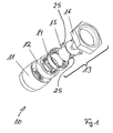
- a cable insertion device 10 has a multi-part construction and comprises at least one base body 11, a sealing body 12 and a pressure body 13.
- the pressure body 13 is formed from three assemblies, namely a pressure disk 14, a pressure plug 15 and a pressure nut 16
- the main body 11, the pressure disk 14, the pressure plug 15 and the pressure nut 16 are made of a relatively stiff, non-elastic material.
- the sealing body 12, however, is made of a deformable and thus elastic material.
- the main body 11 (see FIG. 4), the sealing body 12 (see FIG. 5) and the pressure disk 14 (see FIG. 6) of the pressure body 13 each have a central opening 17, 18 or 19. Through these central openings 17 , 18 and 19 of main body 11, sealing body 12 and thrust washer 14, a plurality of optical fiber cables are feasible.
- sealing body 12 and thrust washer 14 close each radially outward slot-like chambers 20, 21 and 22 at.
- the slit-like chambers 20, 21 and 22 respectively open into the central opening 17, 18 and 19.
- Each of the slit-like chambers 20, 21 and 22 serves to receive an optical fiber cable guided therein optical fibers.
- the guided light waveguide cables are in particular prefabricated patch cords.
- Each optical fiber cable is therefore guided in the separate chambers 20, 21 and 22 of the body 11, sealing body 12 and thrust washer 14 and can be carried out to perform installation work individually and independently of the other fiber optic cables from the slit-shaped chambers 20, 21 and 22 and in the central Openings 17, 18 and 19 are introduced.
- each optical fiber cable is guided independently of the other fiber optic cables and independent of the other fiber optic cables handled.
- the sealing body 12 is positioned between the base body 11 and the pressure plate 14 of the pressure body 13.
- the thrust washer 14 engages in the radial direction projecting lugs or projections 23 in recesses 24 within the body 11 a.
- the recesses 24 of the main body 11 are associated with an inner wall of the main body 11. In this way, a rotation between the base body 11 and the pressure plate 14 of the pressure body 13 is provided.
- the pressure plug 15 engages in the assembled state of the cable insertion device 10 according to the invention in the openings 17, 18 and 19 of the base body 11, sealing body 12 and thrust washer 14 a. Furthermore, the pressure plug 15 engages with radially projecting projections 25 in recesses 26 in the region of the pressure plate 14, so as to in turn to ensure a Verwartik. As can be seen in particular from FIG. 6, the projections 23 of the thrust washer 14, which engage in the recesses 24 of the main body 11, and the recesses 26 of the thrust washer 14, in which the projections 25 of the pressure plug 15 engage, are positioned immediately adjacent to one another.
- the outer diameter of the pressure plug 15 is adapted to the inner diameter of the openings 17, 18 and 19 respectively.
- the cable insertion device 10 In the assembled state of the cable insertion device 10 according to the invention further acts a non-illustrated internal thread of the pressure nut 16 with a likewise not-shown external thread of the main body 11 together.
- a non-illustrated internal thread of the pressure nut 16 By increasing screwing of pressure nut 16 and the base body 11, an increasing pressure on the pressure plug 15 and thus the pressure plate 14 and the sealing body 12 is exercised.
- the elastic sealing body 12 deforms and is pressed against the inner wall of the base body 11.
- the entire cable insertion device 10 is sealed and the optical waveguide cables routed in the cable insertion device 10 are relieved of strain.
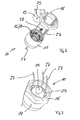
- Fig. 3 shows the cable insertion device 10 according to the invention in the assembled state.
- the pressure plug 15 and the pressure nut 16 release the aligned chambers 20, 21 and 22 of the base body 11, sealing body 12 and thrust washer 14, so that in the chambers 20, 21 and 22 led fiber optic cable can be passed laterally past the pressure plug 15 and through the pressure nut 16.
- Fig. 3 shows a total of three optical fiber cables 27, wherein in each of these optical fiber cable 27, preferably an optical waveguide is guided.
- these optical waveguide cables 27 are, in particular, prefabricated optical waveguide cables, in particular so-called patch cables, which are already equipped with a corresponding plug device 28.
- optical fiber cable 27 can be individually led out of the chambers 20, 21 and 22 and pushed into the central opening 17, 18 and 19 respectively , The led out of the chambers 20, 21 and 22 optical fiber cable 27 are freely displaceable within the openings 17, 18 and 19, so that the installation work can be performed.
- the remaining optical fiber cables 27 remain unaffected.
- the cable entry device 10 is preferably suitable for use on wall distributors.
- the cable insertion device 10 is then attached to the wall distributor over the base body 11, preferably the base body 11 is screwed to a housing of the wall distributor.
- the main body 11 may also be an integral part of the wall distributor, in particular of the housing thereof.
- In the wall distributor to be introduced or be led out of the same optical fiber cable can be performed independently in the cable insertion device according to the invention and intercepted against tensile load.
- individual optical waveguide cables can be handled separately for carrying out installation work, without influencing the other optical waveguide cables routed in the cable insertion device according to the invention.
- twenty-four slot-like chambers 20, 21 and 22 are respectively introduced into the base body 11, the sealing body 12 and the pressure plate 14.
- twenty-four optical fiber cables can be independently guided and handled in the cable insertion device 10 according to the invention.
- stiffening webs 29 and 30 run between the individual slot-like chambers 20 and 22 of base body 11 and pressure disk 14. Stiffening webs 29 and 30 stabilize the shape of base body 11 and pressure disk 14.
Landscapes
- Physics & Mathematics (AREA)
- General Physics & Mathematics (AREA)
- Optics & Photonics (AREA)
- Light Guides In General And Applications Therefor (AREA)
- Electric Cable Installation (AREA)
- Investigating Materials By The Use Of Optical Means Adapted For Particular Applications (AREA)
Description
- Die vorliegende Erfindung betrifft eine Kabeleinführvorrichtung einer Verteilereinrichtung für Lichtwellenleiterkabel gemäß dem Oberbegriff des Anspruchs 1. Des weiteren betrifft die Erfindung eine Verteilereinrichtung mit einer derartigen Kabeleinführvorrichtung gemäß dem Oberbegriff des Anspruchs 9.
- Beim Aufbau von Lichtwellenleiterkabel-Netzwerken werden Verteilereinrichtungen zur Handhabung von Lichtwellenleiterkabein und von in den Lichtwellenleiterkabeln geführten Lichtwellenleitern für die Gewährleistung einer strukturierten Verkabelung benötigt. Bei derartigen Verteilereinrichtungen kann es sich zum Beispiel um Verteilerschränke oder Wandverteiler oder auch Kabelmuffen handeln.
- Eine Anforderung, die an solche Verteilereinrichtungen gestellt wird, ist eine maximale Bestückung derselben bei hoher Packungsdichte und gleichzeitiger geringfügiger mechanischer Beanspruchung der Lichtwellenleiterkabel und der in den Lichtwellenleiterkabeln geführten Lichtwellenleiter. Die in solchen Verteilereinrichtungen handzuhabenden Lichtwellenleiter müssen stressfrei über die Lichtwellenleiterkabel an die Verteilereinrichtungen herangeführt, in dieselbe eingeführt sowie aus derselben herausgeführt werden, wobei im Bereich einer Einführstelle bzw. einer Ausführstelle der Lichtwellenleiterkabel in die bzw. aus der Verteilereinrichtung sogenannte Kabeleinführvorrichtungen zum Einsatz kommen.
- Eine Kabeleinführvorrichtung gemäß dem Oberbegriff des Anspruchs 1 ist aus der
US-A-6 150 608 bekannt. Hinsichtlich weiteren Standes der Technik wird verwiesen aufUS-A-4 795 230 undFR-A-2 563 385 - Hiervon ausgehend liegt der vorliegenden Erfindung das Problem zu Grunde, eine neuartige Kabeleinführvorrichtung einer Verteilereinrichtung zu schaffen. Dieses Problem wird durch eine Kabeleinführvorrichtung mit den Merkmalen des Anspruchs 1 gelöst. Erfindungsgemäß weisen der Grundkörper und der Dichtkörper und eine Druckscheibe des Druckkörpers jeweils eine mittige Öffnung auf, wobei der Grundkörper und der Dichtkörper und die Druckscheibe radial außen anschließend an die jeweilige Öffnung mehrere schlitzartige Kammern zur Aufnahme jeweils eines Lichtwellenleiterkabels aufweisen, wobei die Kammern in die mittige Öffnung münden.
- Mit der erfindungsgemäßen Kabeleinführvorrichtung ist es möglich, gleichzeitig mehrere Lichtwellenleiterkabel in einer einzigen Kabeleinführvorrichtung zu führen, wobei dann, wenn eines dieser Lichtwellenleiterkabel zum Beispiel zur Ausführung von Installationsarbeiten oder Wartungsarbeiten bewegt werden muss, die übrigen Lichtwellenleiterkabel hiervon unbeeinflusst bleiben. Mit der erfindungsgemäßen Kabeleinführvorrichtung ist es demnach möglich, an einzelnen in der Kabeleinführvorrichtung geführten Lichtwellenleiterkabeln gezielt Arbeiten vorzunehmen und gleichzeitig dafür Sorge zu tragen, dass die übrigen Lichtwellenleiterkabel hiervon nicht beeinflusst werden. Dies erhöht einerseits die Sicherheit bei der Handhabung der Kabel und reduziert andererseits die mechanischen Belastungen auf die Lichtwellenleiter, die in den Lichtwellenleiterkabeln geführt sind.
- Nach einer bevorzugten Weiterbildung der Erfindung weist der Druckkörper einen mehrteiligen Aufbau auf, zumindest umfassend die Druckscheibe, einen Druckstopfen und eine Druckmutter. Der Grundkörper, der Dichtkörper und die Druckscheibe des Druckkörpers verfügen jeweils über die mittigen Öffnungen, wobei radial außen anschließend an die jeweilige Öffnung der Grundkörper, der Dichtkörper und die Druckscheibe jeweils mehrere schlitzartige Kammern zur Aufnahme jeweils eines Lichtwellenleiterkabels aufweisen, und wobei die Kammern in die mittige Öffnung münden.
- In zusammengebautem Zustand ist der Dichtkörper zwischen dem Grundkörper und der Druckscheibe positioniert, und die Druckmutter ist derart mit dem Grundkörper verschraubt, dass der Druckstopfen über die Druckscheibe einen Druck auf den Dichtkörper ausübt, sodass sich der Dichtkörper verformt und so eine Abdichtung der Kabeleinführvorrichtung sowie eine Zugentlastung der Lichtwellenleiterkabel erzielt wird.
- Bevorzugte Weiterbildungen der Erfindung ergeben sich aus den Unteransprüchen und der nachfolgenden Beschreibung. Ein Ausführungsbeispiel wird, ohne hierauf beschränkt zu sein, anhand der Zeichnung näher erläutert. In der Zeichnung zeigt:
- Fig. 1:
- eine erfindungsgemäße Kabeleinführvorrichtung für Lichtwellenleiterkabel in einer perspektivischen Explosionsdarstellung;
- Fig. 2:
- die erfindungsgemäße Kabeleinführvorrichtung gemäß Fig. 1 zusammen mit vorkonfektionierten Lichtwellenleiterkabeln in einer Darstellung analog zu Fig. 1;
- Fig. 3:
- die erfindungsgemäße Kabeleinführvorrichtung gemäß Fig. 1 zusammen mit vorkonfektionierten Lichtwellenleiterkabeln in einer perspektivischen Zusammenbaudarstellung;
- Fig. 4:
- einen Grundkörper der erfindungsgemäßen Kabeleinführvorrichtung in perspektivischer Alleindarstellung;
- Fig. 5:
- einen Dichtkörper der erfindungsgemäßen Kabeleinführvorrichtung in perspektivischer Alleindarstellung; und
- Fig. 6:
- eine Druckscheibe eines Druckkörpers der erfindungsgemäßen Kabeleinführvorrichtung in perspektivischer Alleindarstellung.
- Nachfolgend wird ein Ausführungsbeispiel einer erfindungsgemäßen Kabeleinführvorrichtung unter Bezugnahme auf Fig. 1 bis 6 in größerem Detail beschrieben.
- Eine erfindungsgemäße Kabeleinführvorrichtung 10 verfügt über einen mehrteiligen Aufbau und umfasst zumindest einen Grundkörper 11, einen Dichtkörper 12 sowie einen Druckkörper 13. Gemäß Fig. 1 ist der Druckkörper 13 aus drei Baugruppen gebildet, nämlich aus einer Druckscheibe 14, einem Druckstopfen 15 und einer Druckmutter 16. Der Grundkörper 11, die Druckscheibe 14, der Druckstopfen 15 sowie die Druckmutter 16 sind aus einem relativ steifen, nichtelastischen Material gefertigt. Der Dichtkörper 12 hingegen ist aus einem verformbaren und damit elastischen Werkstoff hergestellt.
- Der Grundkörper 11 (siehe Fig.4), der Dichtkörper 12 (siehe Fig. 5) sowie die Druckscheibe 14 (siehe Fig. 6) des Druckkörpers 13 verfügen jeweils über eine mittige Öffnung 17, 18 bzw. 19. Durch diese mittigen Öffnungen 17, 18 bzw. 19 von Grundkörper 11, Dichtkörper 12 bzw. Druckscheibe 14 sind mehrere Lichtwellenleiterkabel führbar. An die Öffnungen 17, 18 und 19 von Grundkörper 11, Dichtkörper 12 sowie Druckscheibe 14 schließen sich jeweils radial außen schlitzartige Kammern 20, 21 bzw. 22 an. Die schlitzartigen Kammern 20, 21 bzw. 22 münden jeweils in die mittige Öffnung 17, 18 bzw. 19. Jede der schlitzartigen Kammern 20, 21 bzw. 22 dient der Aufnahme eines Lichtwellenleiterkabels mit darin geführten Lichtwellenleitern. Bei den geführten Lichtwellenleitekabeln handelt es sich insbesondere um vorkonfektionierte Patchkabel. Jedes Lichtwellenleiterkabel wird demnach in dem separaten Kammern 20, 21 und 22 von Grundkörper 11, Dichtkörper 12 und Druckscheibe 14 geführt und kann zur Ausführung von Installationsarbeiten individuell und unabhängig von den anderen Lichtwellenleiterkabeln aus den schlitzförmigen Kammern 20, 21 und 22 herausgeführt und in die mittigen Öffnungen 17, 18 bzw. 19 einführt werden.
- Insofern ist jedes Lichtwellenleiterkabel unabhängig von den anderen Lichtwellenleiterkabeln geführt und unabhängig von den anderen Lichtwellenleiterkabeln handhabbar.
- Wie insbesondere Fig. 1 entnommen werden kann, ist in einem zusammengebauten Zustand der Kabeleinführvorrichtung 10 der Dichtkörper 12 zwischen dem Grundkörper 11 und der Druckscheibe 14 des Druckkörpers 13 positioniert. In diesem zusammengebauten Zustand greift die Druckscheibe 14 mit in radialer Richtung vorstehenden Nasen bzw. Vorsprüngen 23 in Ausnehmungen 24 innerhalb des Grundkörpers 11 ein. Die Ausnehmungen 24 des Grundkörpers 11 sind einer Innenwand des Grundkörpers 11 zugeordnet. Auf diese Art und Weise wird ein Verdrehschutz zwischen dem Grundkörper 11 und der Druckscheibe 14 des Druckkörpers 13 bereitgestellt. Im zusammengebauten Zustand sind die Kammern 20, 21 und 22 von Grundkörper 11, Dichtkörper 12 und Druckscheibe 14 zueinander fluchtend ausgerichtet, so dass ein handzuhabendes Lichtwellenleiterkabel gleichzeitig in einer Kammer 20 des Grundkörpers, in einer Kammer 21 des Dichtkörpers 12 und in einer Kammer 22 der Druckscheibe 14 geführt ist. Ebenso fluchten im zusammengebauten Zustand die Öffnungen 17, 18 und 19 von Grundkörper 11, Dichtkörper 12 und Druckscheibe 14.
- Wie insbesondere Fig. 1 entnommen werden kann, greift der Druckstopfen 15 in zusammengebautem Zustand der erfindungsgemäßen Kabeleinführvorrichtung 10 in die Öffnungen 17, 18 und 19 von Grundkörper 11, Dichtkörper 12 sowie Druckscheibe 14 ein. Weiterhin greift der Druckstopfen 15 mit radial vorstehenden Vorsprüngen 25 in Ausnehmungen 26 im Bereich der Druckscheibe 14 ein, um so wiederum einen Verdrehschutz zu gewährleisten. Wie insbesondere Fig. 6 entnommen werden kann, sind die Vorsprünge 23 der Druckscheibe 14, die in die Ausnehmungen 24 des Grundkörpers 11 eingreifen, sowie die Ausnehmungen 26 der Druckscheibe 14, in welche die Vorsprünge 25 des Druckstopfens 15 eingreifen, unmittelbar benachbart zueinander positioniert. Da in montiertem Zustand alle in der Kabeleinführvorrichtung 10 geführten Lichtwellenleiterkabel aus den mittigen Öffnungen 17, 18 bzw. 19 herausbewegt und in die schlitzartigen Kammern 20, 21 bzw. 22 eingeführt sind, ist der Außendurchmesser des Druckstopfens 15 an den Innendurchmesser der Öffnungen 17, 18 bzw. 19 angepasst.
- In zusammengebautem Zustand der erfindungsgemäßen Kabeleinführvorrichtung 10 wirkt des weiteren ein nicht-dargestelltes Innengewinde der Druckmutter 16 mit einem ebenfalls nicht-dargestellten Außengewinde des Grundkörpers 11 zusammen. Durch zunehmendes Verschrauben von Druckmutter 16 sowie Grundkörper 11 wird ein zunehmender Druck auf den Drucksstopfen 15 und damit die Druckscheibe 14 und den Dichtkörper 12 ausgeübt. Dabei verformt sich der elastische Dichtkörper 12 und wird gegen die innere Wand des Grundkörpers 11 gedrückt. Durch die sich dabei ausbildende Zwangsverformung des Dichtkörpers 12 wird die gesamte Kabeleinführvorrichtung 10 abgedichtet und die in der Kabeleinführvorrichtung 10 geführten Lichtwellenleiterkabel werden zugentlastet.
- Fig. 3 zeigt die erfindungsgemäße Kabeleinführvorrichtung 10 in zusammengebautem Zustand. Wie Fig. 3 entnommen werden kann, geben in zusammengebautem Zustand der Druckstopfen 15 sowie die Druckmutter 16 die fluchtend zueinander ausgerichteten Kammern 20, 21 sowie 22 von Grundkörper 11, Dichtkörper 12 sowie Druckscheibe 14 frei, sodass die in den Kammern 20, 21 und 22 geführten Lichtwellenleiterkabel seitlich an dem Druckstopfen 15 vorbei und durch die Druckmutter 16 hindurchgeführt werden können. Fig. 3 zeigt insgesamt drei Lichtwellenleiterkabel 27, wobei in jedem dieser Lichtwellenleiterkabel 27 vorzugsweise ein Lichtwellenleiter geführt ist. Wie Fig. 2 entnommen werden kann, handelt es sich bei diesen Lichtwellenleiterkabein 27 insbesondere um vorkonfektionierte Lichtwellenleiterkabel, insbesondere um sogenannte Patchkabel, die bereits mit einer entsprechenden Steckereinrichtung 28 ausgerüstet sind.
- Soll nun zum Beispiel an den Lichtwellenleiterkabeln 27 eine Installationsarbeit durchgeführt werden, so wird die Verschraubung zwischen Grundkörper 11 sowie Druckmutter 16 gelöst, die Druckmutter 16 wird vom Grundkörper 11 abgehoben und der Druckstopfen 15 wird im Sinne der Fig. 2 aus der Anordnung herausgenommen. Hierdurch werden die Öffnungen 17, 18 bzw. 19 freigegeben und die in den Kammern 20, 21 bzw. 22 aufgenommenen Lichtwellenleiterkabel 27 können einzeln aus den Kammern 20, 21 bzw. 22 herausgeführt und in die mittige Öffnung 17, 18 bzw. 19 geschoben werden. Die aus den Kammern 20, 21 bzw. 22 herausgeführten Lichtwellenleiterkabel 27 sind innerhalb der Öffnungen 17, 18 bzw. 19 frei verschiebbar, sodass die Installationsarbeiten ausgeführt werden können. Bei Herausführung eines Lichtwellenleiterkabels 27 aus einer entsprechenden Kammer bleiben die übrigen Lichtwellenleiterkabel 27 unbeeinflusst.
- Die erfindungsgemäße Kabeleinführvorrichtung 10 eignet sich bevorzugt zur Verwendung an Wandverteilern. Die Kabeleinführvorrichtung 10 ist dann am Wandverteiler über den Grundkörper 11 befestigt, vorzugsweise ist der Grundkörper 11 mit einem Gehäuse des Wandverteilers verschraubt. Der Grundkörper 11 kann auch integraler Bestandteil des Wandverteilers, insbesondere des Gehäuses desselben, sein. In den Wandverteiler einzuführende bzw. aus demselben herauszuführende Lichtwellenleiterkabel können in der erfindungsgemäßen Kabeleinführvorrichtung unabhängig voneinander geführt sowie gegenüber Zugbelastung abgefangen werden. Weiterhin sind zur Durchführung von Installationsarbeiten einzelne Lichtwellenleiterkabel separat handhabbar, ohne die übrigen in der erfindungsgemäßen Kabeleinführvorrichtung geführten Lichtwellenleiterkabel zu beeinflussen.
- Im gezeigten Ausführungsbeispiel sind in den Grundkörper 11, den Dichtkörper 12 sowie die Druckscheibe 14 jeweils vierundzwanzig schlitzartige Kammern 20, 21 bzw. 22 eingebracht. Im gezeigten Ausführungsbeispiel können demnach vierundzwanzig Lichtwellenleiterkabel unabhängig voneinander in der erfindungsgemäßen Kabeleinführvorrichtung 10 geführt und gehandhabt werden.
- Wie insbesondere Fig. 4 und 6 entnommen werden kann, verlaufen zwischen den einzelnen schlitzartigen Kammern 20 bzw. 22 von Grundkörper 11 sowie Druckscheibe 14 Versteifungsstege 29 bzw. 30. Die Versteifungssteges 29 bzw. 30 stabilisieren die Form von Grundkörper 11 sowie Druckscheibe 14.
-
- 10
- Kabeleinführvorrichtung
- 11
- Grundkörper
- 12
- Dichtkörper
- 13
- Druckkörper
- 14
- Duckscheibe
- 15
- Druckstopfen
- 16
- Druckmutter
- 17
- Öffnung
- 18
- Öffnung
- 19
- Öffnung
- 20
- Kammer
- 21
- Kammer
- 22
- Kammer
- 23
- Vorsprung
- 24
- Ausnehmung
- 25
- Vorsprung
- 26
- Ausnehmung
- 27
- Lichtwellenleiterkabel
- 28
- Steckereinrichtung
- 29
- Versteifungssteg
- 30
- Versteifungssteg
Claims (9)
- Kabeleinführvorrichtung einer Verteilereinrichtung für Lichtwellenleiterkabel, um Lichtwellenleiterkabel mit in denselben geführten Lichtwellenleitern in die Verteilereinrichtung einzuführen bzw. aus derselben herauszuführen, mit einem mehrteiligen Aufbau zumindest umfassend einen Grundkörper (11), einen Dichtkörper (12) und einen Druckkörper (13), wobei der Grundkörper (11) und der Dichtkörper (12) und der Druckkörper (13) axial angeordnet sind und derart ausgebildet sind, dass in der Kabeleinführvorrichtung mehrere Lichtwellenleiterkabel (27) unabhängig voneinander derart handhabbar sind, dass bei Handhabung eines der Lichtwellenleiterkabel die anderen Lichtwellenleiterkabel unbeeinflusst bleiben, dadurch gekennzeichnet, dass der Grundkörper (11) und der Dichtkörper (12) und eine Druckscheibe (14) des Druckkörpers (13) jeweils eine mittige Öffnung (17, 18, 19) aufweisen, und dass der Grundkörper (11) und der Dichtkörper (12) und die Druckscheibe (14) radial außen anschließend an die jeweilige Öffnung (17, 18, 19) mehrere schlitzartige Kammern (20, 21, 22) zur Aufnahme jeweils eines Lichtwellenleiterkabels (27) aufweisen, wobei die Kammern (20, 21, 22) in die mittige Öffnung (17, 18, 19) münden, so dass die in den Kammern (20, 21, 22) aufgenommenen Lichtwellenleiterkabel (27) zur Durchführung von Installationsarbeiten einzeln aus den Kammern (20, 21, 22) herausgeführt und in die mittige Öffnung (17, 18, 19) geschoben werden können.
- Kabeleinführvorrichtung nach Anspruch 1, dadurch gekennzeichnet, dass der Druckkörper (13) einen mehrteiligen Aufbau aufweist, zumindest umfassend eine Druckscheibe (14), einen Druckstopfen (15) und eine Druckmutter (16).
- Kabeleinführvorrichtung nach Anspruch 1 oder 2, dadurch gekennzeichnet, dass ein Druckstopfen (15) des Druckkörpers (13) in die mittige Öffnung (17, 18, 19) von Druckscheibe (14), Dichtkörper (12) und vorzugsweise auch Grundkörper (11) einführbar ist.
- Kabeleinführvorrichtung nach einem oder mehreren der Ansprüche 2 bis 4, dadurch gekennzeichnet, dass der Druckmutter (16) des Druckkörpers (13) ein Innengewinde zugeordnet ist, welches mit einem dem Grundkörper (11) zugeordneten Außengewinde zusammenwirkt.
- Kabeleinführvorrichtung nach Anspruch 4, dadurch gekennzeichnet, dass die Druckmutter (16) des Druckkörpers (13) derart mit dem Grundkörper (11) verschraubbar ist, dass mit zunehmender Verschraubung der Druckstopfen (15) über die Druckscheibe (14) einen zunehmenden Druck auf den Dichtkörper (12) ausübt, sodass der Dichtkörper (12) verformt wird und so eine Abdichtung der Kabeleinführvorrichtung und eine Zugentlastung der Lichtwellenleiterkabel bereitstellt.
- Kabeleinführvorrichtung nach einem oder mehreren der Ansprüche 1 bis 5, dadurch gekennzeichnet, dass der Grundkörper (11) an einer innenliegenden Wand Ausnehmungen (24) aufweist, in welche in zusammengebautem Zustand die Druckscheibe (14) des Druckkörpers (13) zur Bereitstellung eines Verdrehschutzes mit entsprechenden Vorsprüngen (23) eingreift, wobei in zusammengebautem Zustand der Dichtkörper (12) zwischen dem Grundkörper (11) und der Druckscheibe (14) positioniert ist.
- Kabeleinführvorrichtung nach einem oder mehreren der Ansprüche 1 bis 6, dadurch gekennzeichnet, dass die Druckscheibe (14) des Druckkörpers (13) Ausnehmungen (26) aufweist, in welche in zusammengebautem Zustand der Druckstopfen (15) des Druckkörpers (13) mit entsprechenden Vorsprüngen (25) zur Bereitstellung eines Verdrehschutzes eingreift.
- Kabeleinführvorrichtung nach einem oder mehreren der Ansprüche 1 bis 7, dadurch gekennzeichnet, dass in zusammengebautem Zustand der Druckstopfen (15) und die Druckmutter (16) die von dem Grundkörper (11), dem Dichtkörper (12) und der Druckscheibe (14) begrenzten Kammern (17, 18, 19) derart freigeben, dass die in den Kammern (17, 18, 19) aufgenommenen Lichtwellenleiterkabel (17) seitlich neben dem Druckstopfen (15) vorbeiführbar sind.
- Verteilereinrichtung für Lichtwellenleiterkabel bzw. für in den Lichtwellenleiterkabeln geführte Lichtwellenleiter, insbesondere Wandverteiler, mit mindestens einer Kabeleinführvorrichtung, um Lichtwellenleiterkabel mit in denselben geführten Lichtwellenleitern in die Verteilereinrichtung einzuführen bzw. aus derselben herauszuführen, dadurch gekennzeichnet, dass die oder jede Kabeleinführvorrichtung (10) nach einem oder mehreren der Ansprüche 1 bis 8 ausgebildet ist.
Applications Claiming Priority (2)
| Application Number | Priority Date | Filing Date | Title |
|---|---|---|---|
| DE202004003962U DE202004003962U1 (de) | 2004-03-11 | 2004-03-11 | Kabeleinführvorrichtung einer Verteilereinrichtung für Lichtwellenleiterkabel und Verteilereinrichtung mit einer Kabeleinführvorrichtung |
| PCT/EP2005/000846 WO2005088374A1 (de) | 2004-03-11 | 2005-01-28 | Kabeleinführvorrichtung einer verteilereinrichtung für lichtwellenleiterkabel und verteilereinrichtung mit einer kabeleinführvorrichtung |
Publications (2)
| Publication Number | Publication Date |
|---|---|
| EP1723457A1 EP1723457A1 (de) | 2006-11-22 |
| EP1723457B1 true EP1723457B1 (de) | 2007-12-12 |
Family
ID=34530494
Family Applications (1)
| Application Number | Title | Priority Date | Filing Date |
|---|---|---|---|
| EP05701234A Expired - Lifetime EP1723457B1 (de) | 2004-03-11 | 2005-01-28 | Kabeleinführvorrichtung einer verteilereinrichtung für lichtwellenleiterkabel und verteilereinrichtung mit einer kabeleinführvorrichtung |
Country Status (5)
| Country | Link |
|---|---|
| EP (1) | EP1723457B1 (de) |
| AT (1) | ATE381035T1 (de) |
| DE (2) | DE202004003962U1 (de) |
| ES (1) | ES2298995T3 (de) |
| WO (1) | WO2005088374A1 (de) |
Families Citing this family (2)
| Publication number | Priority date | Publication date | Assignee | Title |
|---|---|---|---|---|
| CN101452098B (zh) * | 2007-10-31 | 2010-07-14 | 宁波东方电缆股份有限公司 | 光电复合海缆的修理接头 |
| BR112013029736A2 (pt) | 2011-05-24 | 2017-01-17 | Corning Cable Sys Llc | arruela de olhal porta três cabos |
Family Cites Families (7)
| Publication number | Priority date | Publication date | Assignee | Title |
|---|---|---|---|---|
| FR2563385B3 (fr) * | 1984-04-19 | 1986-04-11 | Lienart Jean Pierre | Manchon de protection pour la suspension de faisceaux de cables relativement fragiles |
| FR2597616B1 (fr) * | 1986-04-17 | 1988-08-05 | Telecommunications Sa | Dispositif et procede d'epanouissement de fibres optiques sortant d'un cable a raccorder |
| US5315684A (en) * | 1991-06-12 | 1994-05-24 | John Mezzalingua Assoc. Inc. | Fiber optic cable end connector |
| DE9300623U1 (de) * | 1993-01-19 | 1993-03-25 | OSI Kommunikations- und Systemtechnik GmbH, 8873 Ichenhausen | Bau- und Montagesatz für Lichtleiterübertragungsstrecken in Datenverarbeitungsanlagen |
| DE4417152A1 (de) * | 1994-05-17 | 1995-11-23 | Siemens Ag | Schrumpfbare Mehrfachkabeleinführung |
| PE69897A1 (es) * | 1996-05-02 | 1997-11-05 | Raychem Sa Nv | Cierre para sellar una abertura |
| US6488317B1 (en) * | 2000-02-01 | 2002-12-03 | Avaya Technology Corp. | Cable strain relief adapter with gel sealing grommet |
-
2004
- 2004-03-11 DE DE202004003962U patent/DE202004003962U1/de not_active Expired - Lifetime
-
2005
- 2005-01-28 ES ES05701234T patent/ES2298995T3/es not_active Expired - Lifetime
- 2005-01-28 AT AT05701234T patent/ATE381035T1/de not_active IP Right Cessation
- 2005-01-28 EP EP05701234A patent/EP1723457B1/de not_active Expired - Lifetime
- 2005-01-28 DE DE502005002225T patent/DE502005002225D1/de not_active Expired - Lifetime
- 2005-01-28 WO PCT/EP2005/000846 patent/WO2005088374A1/de not_active Ceased
Also Published As
| Publication number | Publication date |
|---|---|
| EP1723457A1 (de) | 2006-11-22 |
| WO2005088374A1 (de) | 2005-09-22 |
| DE202004003962U1 (de) | 2005-04-28 |
| ES2298995T3 (es) | 2008-05-16 |
| DE502005002225D1 (de) | 2008-01-24 |
| ATE381035T1 (de) | 2007-12-15 |
Similar Documents
| Publication | Publication Date | Title |
|---|---|---|
| EP2005547B1 (de) | Dichtungskörper einer kabelmuffe | |
| EP1656720B1 (de) | Abfangvorrichtung für optische kabel sowie kabelmuffe | |
| EP2005230B1 (de) | Dichtungskörper einer kabelmuffe | |
| EP2901195B1 (de) | Kabelkontaktierungswitterungsschutz | |
| EP2251729B1 (de) | Kabelmuffe mit Kabelabdichtvorrichtung | |
| EP0608517A1 (de) | Gehäuse für passive optische Komponenten | |
| DE9206511U1 (de) | Verzweiger für Lichtleitfaser-Kabel | |
| DE202013012284U1 (de) | Kabelabdichtungseinheit mit mehreren Abdichtungsmodulen | |
| DE60101402T2 (de) | Randverklebte aber teilbare faseroptische Bandkabel | |
| DE102008004576A1 (de) | Schutz- und Führungsvorrichtung für ein Kabel oder dergleichen | |
| DE69832128T2 (de) | Gehäuse für Kabelverbindung | |
| EP1723457B1 (de) | Kabeleinführvorrichtung einer verteilereinrichtung für lichtwellenleiterkabel und verteilereinrichtung mit einer kabeleinführvorrichtung | |
| EP2198335B1 (de) | Vorrichtung zur abfangung von lichtwellenleiterkabeln | |
| DE102019121480A1 (de) | Verbindungsbrücke sowie System zur Führung von Lichtwellenleitern | |
| EP0904618B1 (de) | Schaltvorrichtung wie schütze sowie verfahren zur bereitstellung solcher schaltvorrichtung | |
| DE29920298U1 (de) | Führung und Umlenkung für Lichtwellenleiter | |
| DE69718070T2 (de) | Verbindung für faseroptische kabel | |
| AT3404U1 (de) | Führung und umlenkung für lichtwellenleiter | |
| DE3603616A1 (de) | Vorrichtung zur aufteilung mehrfasriger lichtwellenleiterkabel mit integrierter zugentlastung | |
| EP3072196B1 (de) | Kabelbefestigungsvorrichtung | |
| DE102017108605A1 (de) | Strangdurchführungssystem und Verfahren zur Montage | |
| EP4495652A1 (de) | Kassettenhalter für spleisskassetten | |
| DE8812943U1 (de) | Schutzeinrichtung für einen Lichtwellenleiterverbinder | |
| DE29916731U1 (de) | Kabelführungs-, Halte- und Schutzelement zum Halten eines Lichtwellenleiterkabels | |
| DE4040528A1 (de) | Vorrichtung zur speicherung von ueberlaengen von lichtleitfasern |
Legal Events
| Date | Code | Title | Description |
|---|---|---|---|
| PUAI | Public reference made under article 153(3) epc to a published international application that has entered the european phase |
Free format text: ORIGINAL CODE: 0009012 |
|
| 17P | Request for examination filed |
Effective date: 20060818 |
|
| AK | Designated contracting states |
Kind code of ref document: A1 Designated state(s): AT BE BG CH CY CZ DE DK EE ES FI FR GB GR HU IE IS IT LI LT LU MC NL PL PT RO SE SI SK TR |
|
| 17Q | First examination report despatched |
Effective date: 20070115 |
|
| DAX | Request for extension of the european patent (deleted) | ||
| GRAP | Despatch of communication of intention to grant a patent |
Free format text: ORIGINAL CODE: EPIDOSNIGR1 |
|
| GRAS | Grant fee paid |
Free format text: ORIGINAL CODE: EPIDOSNIGR3 |
|
| GRAA | (expected) grant |
Free format text: ORIGINAL CODE: 0009210 |
|
| AK | Designated contracting states |
Kind code of ref document: B1 Designated state(s): AT BE BG CH CY CZ DE DK EE ES FI FR GB GR HU IE IS IT LI LT LU MC NL PL PT RO SE SI SK TR |
|
| REG | Reference to a national code |
Ref country code: GB Ref legal event code: FG4D Free format text: NOT ENGLISH |
|
| REG | Reference to a national code |
Ref country code: CH Ref legal event code: EP |
|
| REG | Reference to a national code |
Ref country code: IE Ref legal event code: FG4D Free format text: LANGUAGE OF EP DOCUMENT: GERMAN |
|
| REF | Corresponds to: |
Ref document number: 502005002225 Country of ref document: DE Date of ref document: 20080124 Kind code of ref document: P |
|
| GBT | Gb: translation of ep patent filed (gb section 77(6)(a)/1977) |
Effective date: 20080225 |
|
| PG25 | Lapsed in a contracting state [announced via postgrant information from national office to epo] |
Ref country code: SE Free format text: LAPSE BECAUSE OF FAILURE TO SUBMIT A TRANSLATION OF THE DESCRIPTION OR TO PAY THE FEE WITHIN THE PRESCRIBED TIME-LIMIT Effective date: 20080312 |
|
| REG | Reference to a national code |
Ref country code: ES Ref legal event code: FG2A Ref document number: 2298995 Country of ref document: ES Kind code of ref document: T3 |
|
| PG25 | Lapsed in a contracting state [announced via postgrant information from national office to epo] |
Ref country code: FI Free format text: LAPSE BECAUSE OF FAILURE TO SUBMIT A TRANSLATION OF THE DESCRIPTION OR TO PAY THE FEE WITHIN THE PRESCRIBED TIME-LIMIT Effective date: 20071212 Ref country code: SI Free format text: LAPSE BECAUSE OF FAILURE TO SUBMIT A TRANSLATION OF THE DESCRIPTION OR TO PAY THE FEE WITHIN THE PRESCRIBED TIME-LIMIT Effective date: 20071212 Ref country code: LT Free format text: LAPSE BECAUSE OF FAILURE TO SUBMIT A TRANSLATION OF THE DESCRIPTION OR TO PAY THE FEE WITHIN THE PRESCRIBED TIME-LIMIT Effective date: 20071212 Ref country code: NL Free format text: LAPSE BECAUSE OF FAILURE TO SUBMIT A TRANSLATION OF THE DESCRIPTION OR TO PAY THE FEE WITHIN THE PRESCRIBED TIME-LIMIT Effective date: 20071212 Ref country code: PL Free format text: LAPSE BECAUSE OF FAILURE TO SUBMIT A TRANSLATION OF THE DESCRIPTION OR TO PAY THE FEE WITHIN THE PRESCRIBED TIME-LIMIT Effective date: 20071212 |
|
| NLV1 | Nl: lapsed or annulled due to failure to fulfill the requirements of art. 29p and 29m of the patents act | ||
| BERE | Be: lapsed |
Owner name: CCS TECHNOLOGY, INC. Effective date: 20080131 |
|
| PG25 | Lapsed in a contracting state [announced via postgrant information from national office to epo] |
Ref country code: CZ Free format text: LAPSE BECAUSE OF FAILURE TO SUBMIT A TRANSLATION OF THE DESCRIPTION OR TO PAY THE FEE WITHIN THE PRESCRIBED TIME-LIMIT Effective date: 20071212 Ref country code: IS Free format text: LAPSE BECAUSE OF FAILURE TO SUBMIT A TRANSLATION OF THE DESCRIPTION OR TO PAY THE FEE WITHIN THE PRESCRIBED TIME-LIMIT Effective date: 20080412 |
|
| ET | Fr: translation filed | ||
| PG25 | Lapsed in a contracting state [announced via postgrant information from national office to epo] |
Ref country code: SK Free format text: LAPSE BECAUSE OF FAILURE TO SUBMIT A TRANSLATION OF THE DESCRIPTION OR TO PAY THE FEE WITHIN THE PRESCRIBED TIME-LIMIT Effective date: 20071212 Ref country code: RO Free format text: LAPSE BECAUSE OF FAILURE TO SUBMIT A TRANSLATION OF THE DESCRIPTION OR TO PAY THE FEE WITHIN THE PRESCRIBED TIME-LIMIT Effective date: 20071212 Ref country code: MC Free format text: LAPSE BECAUSE OF NON-PAYMENT OF DUE FEES Effective date: 20080131 |
|
| PG25 | Lapsed in a contracting state [announced via postgrant information from national office to epo] |
Ref country code: PT Free format text: LAPSE BECAUSE OF FAILURE TO SUBMIT A TRANSLATION OF THE DESCRIPTION OR TO PAY THE FEE WITHIN THE PRESCRIBED TIME-LIMIT Effective date: 20080512 |
|
| REG | Reference to a national code |
Ref country code: IE Ref legal event code: FD4D |
|
| PLBE | No opposition filed within time limit |
Free format text: ORIGINAL CODE: 0009261 |
|
| STAA | Information on the status of an ep patent application or granted ep patent |
Free format text: STATUS: NO OPPOSITION FILED WITHIN TIME LIMIT |
|
| PG25 | Lapsed in a contracting state [announced via postgrant information from national office to epo] |
Ref country code: DK Free format text: LAPSE BECAUSE OF FAILURE TO SUBMIT A TRANSLATION OF THE DESCRIPTION OR TO PAY THE FEE WITHIN THE PRESCRIBED TIME-LIMIT Effective date: 20071212 Ref country code: IE Free format text: LAPSE BECAUSE OF FAILURE TO SUBMIT A TRANSLATION OF THE DESCRIPTION OR TO PAY THE FEE WITHIN THE PRESCRIBED TIME-LIMIT Effective date: 20071212 |
|
| 26N | No opposition filed |
Effective date: 20080915 |
|
| PG25 | Lapsed in a contracting state [announced via postgrant information from national office to epo] |
Ref country code: GR Free format text: LAPSE BECAUSE OF FAILURE TO SUBMIT A TRANSLATION OF THE DESCRIPTION OR TO PAY THE FEE WITHIN THE PRESCRIBED TIME-LIMIT Effective date: 20080313 Ref country code: EE Free format text: LAPSE BECAUSE OF FAILURE TO SUBMIT A TRANSLATION OF THE DESCRIPTION OR TO PAY THE FEE WITHIN THE PRESCRIBED TIME-LIMIT Effective date: 20071212 |
|
| PG25 | Lapsed in a contracting state [announced via postgrant information from national office to epo] |
Ref country code: BE Free format text: LAPSE BECAUSE OF NON-PAYMENT OF DUE FEES Effective date: 20080131 |
|
| PG25 | Lapsed in a contracting state [announced via postgrant information from national office to epo] |
Ref country code: BG Free format text: LAPSE BECAUSE OF FAILURE TO SUBMIT A TRANSLATION OF THE DESCRIPTION OR TO PAY THE FEE WITHIN THE PRESCRIBED TIME-LIMIT Effective date: 20080312 Ref country code: AT Free format text: LAPSE BECAUSE OF NON-PAYMENT OF DUE FEES Effective date: 20080128 |
|
| PG25 | Lapsed in a contracting state [announced via postgrant information from national office to epo] |
Ref country code: CY Free format text: LAPSE BECAUSE OF FAILURE TO SUBMIT A TRANSLATION OF THE DESCRIPTION OR TO PAY THE FEE WITHIN THE PRESCRIBED TIME-LIMIT Effective date: 20071212 |
|
| REG | Reference to a national code |
Ref country code: CH Ref legal event code: PL |
|
| PG25 | Lapsed in a contracting state [announced via postgrant information from national office to epo] |
Ref country code: CH Free format text: LAPSE BECAUSE OF NON-PAYMENT OF DUE FEES Effective date: 20090131 Ref country code: LI Free format text: LAPSE BECAUSE OF NON-PAYMENT OF DUE FEES Effective date: 20090131 |
|
| PGFP | Annual fee paid to national office [announced via postgrant information from national office to epo] |
Ref country code: ES Payment date: 20100126 Year of fee payment: 6 |
|
| PGFP | Annual fee paid to national office [announced via postgrant information from national office to epo] |
Ref country code: FR Payment date: 20100205 Year of fee payment: 6 Ref country code: IT Payment date: 20100126 Year of fee payment: 6 |
|
| PGFP | Annual fee paid to national office [announced via postgrant information from national office to epo] |
Ref country code: GB Payment date: 20100125 Year of fee payment: 6 Ref country code: TR Payment date: 20100107 Year of fee payment: 6 |
|
| PG25 | Lapsed in a contracting state [announced via postgrant information from national office to epo] |
Ref country code: HU Free format text: LAPSE BECAUSE OF FAILURE TO SUBMIT A TRANSLATION OF THE DESCRIPTION OR TO PAY THE FEE WITHIN THE PRESCRIBED TIME-LIMIT Effective date: 20080613 Ref country code: LU Free format text: LAPSE BECAUSE OF NON-PAYMENT OF DUE FEES Effective date: 20080128 |
|
| GBPC | Gb: european patent ceased through non-payment of renewal fee |
Effective date: 20110128 |
|
| REG | Reference to a national code |
Ref country code: FR Ref legal event code: ST Effective date: 20110930 |
|
| PG25 | Lapsed in a contracting state [announced via postgrant information from national office to epo] |
Ref country code: FR Free format text: LAPSE BECAUSE OF NON-PAYMENT OF DUE FEES Effective date: 20110131 |
|
| PG25 | Lapsed in a contracting state [announced via postgrant information from national office to epo] |
Ref country code: GB Free format text: LAPSE BECAUSE OF NON-PAYMENT OF DUE FEES Effective date: 20110128 |
|
| PG25 | Lapsed in a contracting state [announced via postgrant information from national office to epo] |
Ref country code: IT Free format text: LAPSE BECAUSE OF NON-PAYMENT OF DUE FEES Effective date: 20110128 |
|
| REG | Reference to a national code |
Ref country code: ES Ref legal event code: FD2A Effective date: 20120220 |
|
| PG25 | Lapsed in a contracting state [announced via postgrant information from national office to epo] |
Ref country code: ES Free format text: LAPSE BECAUSE OF NON-PAYMENT OF DUE FEES Effective date: 20110129 |
|
| PG25 | Lapsed in a contracting state [announced via postgrant information from national office to epo] |
Ref country code: TR Free format text: LAPSE BECAUSE OF NON-PAYMENT OF DUE FEES Effective date: 20110128 |
|
| PGFP | Annual fee paid to national office [announced via postgrant information from national office to epo] |
Ref country code: DE Payment date: 20150128 Year of fee payment: 11 |
|
| REG | Reference to a national code |
Ref country code: DE Ref legal event code: R119 Ref document number: 502005002225 Country of ref document: DE |
|
| PG25 | Lapsed in a contracting state [announced via postgrant information from national office to epo] |
Ref country code: DE Free format text: LAPSE BECAUSE OF NON-PAYMENT OF DUE FEES Effective date: 20160802 |