EP1723873B1 - Arbeitsplatte für industrielle Caterings-Küchen - Google Patents
Arbeitsplatte für industrielle Caterings-Küchen Download PDFInfo
- Publication number
- EP1723873B1 EP1723873B1 EP06114266A EP06114266A EP1723873B1 EP 1723873 B1 EP1723873 B1 EP 1723873B1 EP 06114266 A EP06114266 A EP 06114266A EP 06114266 A EP06114266 A EP 06114266A EP 1723873 B1 EP1723873 B1 EP 1723873B1
- Authority
- EP
- European Patent Office
- Prior art keywords
- flat
- flat plate
- worktop
- resting
- ground
- Prior art date
- Legal status (The legal status is an assumption and is not a legal conclusion. Google has not performed a legal analysis and makes no representation as to the accuracy of the status listed.)
- Expired - Lifetime
Links
Images
Classifications
-
- A—HUMAN NECESSITIES
- A47—FURNITURE; DOMESTIC ARTICLES OR APPLIANCES; COFFEE MILLS; SPICE MILLS; SUCTION CLEANERS IN GENERAL
- A47B—TABLES; DESKS; OFFICE FURNITURE; CABINETS; DRAWERS; GENERAL DETAILS OF FURNITURE
- A47B77/00—Kitchen cabinets
- A47B77/02—General layout, e.g. relative arrangement of compartments, working surface or surfaces, supports for apparatus
- A47B77/022—Work tops
-
- A—HUMAN NECESSITIES
- A47—FURNITURE; DOMESTIC ARTICLES OR APPLIANCES; COFFEE MILLS; SPICE MILLS; SUCTION CLEANERS IN GENERAL
- A47B—TABLES; DESKS; OFFICE FURNITURE; CABINETS; DRAWERS; GENERAL DETAILS OF FURNITURE
- A47B47/00—Cabinets, racks or shelf units, characterised by features related to dismountability or building-up from elements
- A47B47/0008—Three-dimensional corner connectors, the legs thereof being received within hollow, elongated frame members
-
- F—MECHANICAL ENGINEERING; LIGHTING; HEATING; WEAPONS; BLASTING
- F16—ENGINEERING ELEMENTS AND UNITS; GENERAL MEASURES FOR PRODUCING AND MAINTAINING EFFECTIVE FUNCTIONING OF MACHINES OR INSTALLATIONS; THERMAL INSULATION IN GENERAL
- F16B—DEVICES FOR FASTENING OR SECURING CONSTRUCTIONAL ELEMENTS OR MACHINE PARTS TOGETHER, e.g. NAILS, BOLTS, CIRCLIPS, CLAMPS, CLIPS OR WEDGES; JOINTS OR JOINTING
- F16B12/00—Jointing of furniture or the like, e.g. hidden from exterior
- F16B12/44—Leg joints; Corner joints
-
- F—MECHANICAL ENGINEERING; LIGHTING; HEATING; WEAPONS; BLASTING
- F16—ENGINEERING ELEMENTS AND UNITS; GENERAL MEASURES FOR PRODUCING AND MAINTAINING EFFECTIVE FUNCTIONING OF MACHINES OR INSTALLATIONS; THERMAL INSULATION IN GENERAL
- F16B—DEVICES FOR FASTENING OR SECURING CONSTRUCTIONAL ELEMENTS OR MACHINE PARTS TOGETHER, e.g. NAILS, BOLTS, CIRCLIPS, CLAMPS, CLIPS OR WEDGES; JOINTS OR JOINTING
- F16B12/00—Jointing of furniture or the like, e.g. hidden from exterior
- F16B12/44—Leg joints; Corner joints
- F16B12/52—Metal leg connections
-
- F—MECHANICAL ENGINEERING; LIGHTING; HEATING; WEAPONS; BLASTING
- F16—ENGINEERING ELEMENTS AND UNITS; GENERAL MEASURES FOR PRODUCING AND MAINTAINING EFFECTIVE FUNCTIONING OF MACHINES OR INSTALLATIONS; THERMAL INSULATION IN GENERAL
- F16B—DEVICES FOR FASTENING OR SECURING CONSTRUCTIONAL ELEMENTS OR MACHINE PARTS TOGETHER, e.g. NAILS, BOLTS, CIRCLIPS, CLAMPS, CLIPS OR WEDGES; JOINTS OR JOINTING
- F16B12/00—Jointing of furniture or the like, e.g. hidden from exterior
- F16B12/44—Leg joints; Corner joints
- F16B2012/446—Leg joints; Corner joints with three-dimensional corner element, the legs thereof being inserted in hollow frame members
Definitions
- the present invention relates to a worktop for industrial catering kitchens.
- Worktops for industrial catering kitchens are normally formed by flat supporting and stiffening frame of essentially rectangular shape arranged at a predetermined height from the ground, by four legs resting on the ground fastened to the flat supporting frame at the four vertexes of the same, and by an upper horizontal top stably fastened to the supporting frame and integrally covering the same. e.g. as disclosed in GB 1441547 .
- the flat frame consists of a rectangular cornice formed by four square section tubular bars made of stainless steel and head-welded one to the other, and by a series of internal stiffening crosspieces which connect together the tubular bars defining the two larger sides of the rectangular, while each of the four legs resting on the ground is formed by a square section tubular bar of stainless steel whose upper end is rigidly fastened to the rectangular cornice by means of screws, rivets or welding.
- the flat frame may also be provided with a rectangular Formica, chipboard or MDF (standing for "Middle Density Fibreboard”) panel horizontally fastened over the rectangular metal cornice.
- MDF Middle Density Fibreboard
- the upper top is instead made of a rectangular stainless steel tray which has four sides of height essentially equal to the thickness of the rectangular cornice and is dimensioned so as to be fitted in reversed position on the rectangular cornice, so as to completely cover it.
- the present invention relates to the manufacturing of a worktop for industrial catering kitchens comprising a flat supporting frame of essentially rectangular shape and which extends in horizontal position to a pre-established height from the ground, four legs resting on the ground fastened to the flat frame at the four vertexes of the same, and finally an upper horizontal top stably fastened onto the flat supporting frame;
- said worktop being characterised in that said flat supporting frame comprises a flat plate of essentially rectangular shape which has four side borders appropriately folded so as to define the four lateral sides of the flat frame, and four angular elements which are positioned at the four vertexes of the rectangle defining the external perimeter of the flat plate; each angular element being provided with a resting base which is adapted to be abuttedly arranged on the flat plate at a vertex of the same and to be immovably entrapped underneath the two side borders of the flat plate there converging, and with a fastening hub which overhangingly protrudes from the resting base and is shaped so as to
- the worktop 1 is essentially formed by a flat supporting and stiffening frame 2 of essentially rectangular shape and which is horizontally arranged at a predetermined height from the ground, by four legs 3 resting on the ground fastened to the flat supporting frame 2 at the four vertexes of the same, and finally by an upper horizontal top 4 stably fastened to the supporting frame 2 and integrally covering the same.
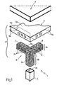
- the flat frame 2 essentially consists of a flat metal plate 5 of essentially rectangular shape which has four side borders folded in an essentially C-shape or O-shape so as to define the four sides of the flat frame 2, and by four angular elements 6 which are positioned at the four vertexes of the rectangular defining the external perimeter of the flat plate 5, and are entrapped underneath the four side borders of the flat plate 5 so as to be rigidly and immovably fastened to the latter.
- each angular element 6 is provided with a resting base 6a to the plate which is adapted to be abuttedly arranged on the flat plate 5 at a vertex of the same and to be entrapped underneath the two side borders of the flat plate 5 there converging, and with a fastening hub 6b which overhangingly protrudes from the resting base 6a in a direction essentially perpendicular to the laying plane of the flat frame 2, and is shaped so as to be engaged by plastic deformation inside with an appropriate central hole 3a obtained on the upper end of the legs 3 resting on the ground.
- each of the four legs 3 resting on the ground is essentially formed by a straight square section tubular bar preferably, but not necessarily, of stainless steel, and the fastening hub 6b is adapted to be engaged by plastic deformation inside the central cavity 3a of the square section tubular bar.
- the four legs 3 resting on the ground may be made of other metallic material.
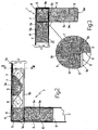
- the flat metal plate 5 consists of a flat plate which presents a central portion 5a of rectangular shape whose peripheral edge defines the external perimeter of the flat plate 5 and the flat frame 2, and four flat appendixes which overhangingly protrude from the four sides of the central portion 5a and are adapted to be folded on themselves essentially C-shaped or O-shaped so as to define, on the four sides of the central portion 5a, as many boxed stiffening crosspieces of the flat plate 5.
- the two flat appendixes 5b which overhangingly protrude from the two longer sides of the central portion 5a are adapted to be folded on themselves essentially O-shaped so as to form two stiffening crosspieces of essentially square tubular section which define the longer sides of the flat plate 5 and of the flat frame 2, while the two flat appendixes 5c which overhangingly protrude from the two shorter sides of the central portion 5a are adapted to be folded on themselves essentially C-shaped so as to form two boxed C-section stiffening crosspieces which define the shorter sides of the flat plate 5 and of the flat frame 2.
- each of them is formed by three complex section straight beams which overhangingly protrude from a same central nucleus maintaining themselves coaxial to as many essentially and reciprocally orthogonal longitudinal reference axis.
- two of the three beams of the angular element 6, below indicated by numbers 7 and 8 are arranged according to an L-configuration, extend on the laying plane of the flat frame 2 parallelly to the central portion 5a of the flat plate 5, and are profiled so as to form a flat surface with which the entire angular element 6 is abuttedly arranged on the surface of the central portion 5a of the flat plate 5.
- the beams 7 and 8 define the resting base 6a of the angular element 6.
- beam 7 has a transversal section whose shape is complementary to that of the boxed stiffening crosspiece which forms the longer side of the flat plate 5 and of the flat frame 2
- beam 8 has a transversal section whose shape is complementary to that of the boxed stiffening crosspiece which forms the shorter side of the flat plate 5 and of the flat frame 2, so that the two beams 7 and 8 of the angular element 6 may be wrapped and entrapped inside said boxed stiffening crosspieces 5, when the flat appendixes 5b and 5c of the flat plate 5 are folded on themselves by chamfering to form said boxed stiffening crosspieces.
- the beams 7 and 8 have a square section.
- the third beam of the angular element 6, below indicated by number 9, overhangingly protrudes from the joint zone between the two beams 7 and 8, on the opposite side of the flat resting surface of the central portion 5a, and is shaped so as to be engaged by plastic deformation inside the central hole 3a obtained on the upper end of the legs 3 resting on the ground, therefore defining the fastening hub 6b of the angular element 6.
- beam 9 has an H-transversal section which approximates by excess the dimensions of the central cavity 3a of the square section tubular metallic bar which forms each leg 3, and is further provided with a fastening tongue 10 which protrudes from the central core 9a of the beam 9 in a direction essentially perpendicular to the longitudinal axis of the beam, and has a length so as to locally protrude outside the shape of the beam 9.
- the tongue 10 is also structured so as to elastically bend when the leg 3 resting on the ground is forcefully keyed onto the beam 9, i.e. to the fastening hub 6b of the angular element 6, and then to drive itself onto the internal surface of the leg 3 so as to rigidly lock the leg 3 on the angular element 6.
- beam 9 extends perpendicularly to the laying plane of the flat frame 2.
- the two beams 7 and 8 which form the resting base 6a of each angular element 6 are finally provided with specific windows or through openings 11 for fastening inside which some portions of the four flat appendixes 5b, 5c of the flat plate 5 are adapted to be wedged by cold plastic deformation.
- each of them is made by moulding of polyamide resin filled with fibreglass in a percentage by weight comprised between 10% and 50% and preferably, but not necessarily, equal to 30%.
- the horizontal top 4 finally consists of a rectangular tray preferably but not necessarily of stainless steel, which has the four sides of height essentially equal to the thickness of the four boxed stiffening crosspieces of the flat plate 5, i.e. the thickness of the four sides of the flat frame 2, and is dimensioned so as to be fitted on the flat plate 5 in reversed position, so as to cover it completely.
- the horizontal top 4 is made of stainless steel as the four resting legs 3 on the ground and the flat plate 5, and is fastened to the flat plate 5 by means of a layer of glue interposed between the two elements.
- the flat supporting frame 2 is obtained from a simple flat stainless steel plate or other metallic material by means of a series of cold pressing and bending operations, with considerably reduced manufacturing costs with respect to the current solutions.
- the particular structure of the flat frame 2 also offers the possibility of fitting the legs 3 resting on the ground directly in the place of use extremely rapidly and without the need for particular tools, thus allowing to considerably reduce shipping costs.
Landscapes
- Engineering & Computer Science (AREA)
- General Engineering & Computer Science (AREA)
- Mechanical Engineering (AREA)
- Floor Finish (AREA)
- Devices For Warming Or Keeping Food Or Tableware Hot (AREA)
- Table Devices Or Equipment (AREA)
- Sink And Installation For Waste Water (AREA)
- Assembled Shelves (AREA)
- Handcart (AREA)
- Table Equipment (AREA)
Claims (12)
- Arbeitsplatte (1) für Großküchen mit einem flachen Stützrahmen (2), der im Wesentlichen rechteckig ist und sich in horizontaler Position zu einer vorbestimmten Höhe vom Boden erstreckt, vier Beinen (3), die auf dem Boden stehen und an den vier Ecken des flachen Rahmens (2) an diesem befestigt sind, und schließlich einer oberen horizontalen Platte (4), die stabil auf dem flachen Stützrahmen (2) befestigt ist, wobei die Arbeitsplatte (1) dadurch gekennzeichnet ist, dass der flache Stützrahmen (2) eine flache, im Wesentlichen rechteckige Platte (5) mit vier Seitenrändern (5b, 5c), die angemessen geklappt sind, um die vier lateralen Seiten des flachen Rahmens (2) zu bilden, und vier winkelförmige Elemente (6) aufweist, die an den vier Ecken des den Außenumfang der flachen Platte (5) definierenden Rechtecks positioniert sind, wobei jedes winkelförmige Element (6) mit einer Aufliegebasis (6a), die geeignet ist, anschlagmäßig an der flachen Platte (5) an einer ihrer Ecken angeordnet zu werden und unter den beiden Seitenrändern (5b, 5c) der flachen Platte (5), die dort zusammenlaufen, unbeweglich gefangen zu sein, und mit einer Befestigungsnabe (6b) versehen ist, die von der Aufliegebasis (6a) überhängend vorsteht und so geformt ist, dass sie durch plastische Verformung in ein vorgesehenes Loch (3a) eingreift, das sich am oberen Ende der auf dem Boden stehenden Beine (3) befindet.
- Arbeitsplatte nach Anspruch 1, dadurch gekennzeichnet, dass die flache Platte (5) einen im Wesentlichen rechteckigen mittleren Abschnitt (5a) aufweist, dessen Umfangsrand den Außenumfang des flachen Rahmens (2) definiert, und durch vier flache Fortsätze (5b, 5c), die von den vier Seiten des mittleren Abschnitts (5a) überhängend vorstehen und im Wesentlichen C-förmig oder 0-förmig umgeklappt sind, um an den vier Seiten des mittleren Abschnitts (5a) die gleiche Anzahl Einbau-Versteifungsquerstücke zu definieren, die die Seitenschalen des flachen Rahmens (2) bilden.
- Arbeitsplatte nach Anspruch 2, dadurch gekennzeichnet, dass mindestens ein winkelförmiges Element (6) einen ersten (7), einen zweiten (8) und einen dritten geraden Balken (9) mit komplexem Querschnitt aufweist, die von demselben mittleren Kern überhängend vorstehen und sich zur gleichen Anzahl gegenseitig im Wesentlichen orthogonaler Längsbezugsachsen koaxial halten, wobei der erste (7) und der zweite Balken (8) in einer L-Konfiguration angeordnet sind, so dass sie anschlagsmäßig am mittleren Abschnitt (5a) der flachen Platte (5) angeordnet sind, und auch geeignet sind, in den Einbau-Versteifungsquerstücken eingeschlossen und durch Abfasen gefangen zu sein, die die Seitenschalen des flachen Rahmens (2) bilden, wenn die flachen Fortsätze (5b, 5c) der flachen Platte (5) umgeklappt sind und die Einbau-Versteifungsquerstücke bilden.
- Arbeitsplatte nach Anspruch 3, dadurch gekennzeichnet, dass der dritte Balken (9) von der Fugenzone zwischen dem ersten (7) und dem zweiten Balken (8) auf der gegenüberliegenden Seite des mittleren Abschnitts (5a) überhängend vorsteht und so geformt ist, dass er durch plastische Verformung in das Loch (3a) eingreift, das sich am oberen Ende des auf dem Boden stehenden Beins (3) befindet.
- Arbeitsplatte nach Anspruch 4, dadurch gekennzeichnet, dass der dritte Balken (9) des winkelförmigen Elements (6) einen Querschnitt hat, der etwas größer ist als die Abmessungen des Lochs (3a), das sich am oberen Ende des auf dem Boden stehenden Beins (3) befindet.
- Arbeitsplatte nach Anspruch 4 oder 5, dadurch gekennzeichnet, dass der dritte Balken (9) des winkelförmigen Elements (6) mit einer Befestigungszunge (10) versehen ist, die örtlich außen von der Kontur des dritten Balkens (9) vorsteht und so konfiguriert ist, dass sie sich elastisch biegt, wenn das Bein (3) hart auf den dritten Balken (9) verkeilt wird, und sich anschließend auf die Innenfläche des Beins (3) schiebt, um es starr in seiner Position zu arretieren.
- Arbeitsplatte nach einem der vorhergehenden Ansprüche, dadurch gekennzeichnet, dass mindestes ein auf dem Boden stehendes Bein (3) durch eine rohrförmige Stange (3) aus Metall mit quadratischem Querschnitt gebildet ist.
- Arbeitsplatte nach Anspruch 7, dadurch gekennzeichnet, dass die rohrförmige Stange (3) aus Metall mit quadratischem Querschnitt aus Edelstahl hergestellt ist.
- Arbeitsplatte nach einem der vorhergehenden Ansprüche, dadurch gekennzeichnet, dass die horizontale Platte (4) eine im Wesentlichen rechteckige Schale (4) mit vier Seiten umfasst, deren Höhe der Dicke der vier Einbau-Versteifungsquerstücke der flachen Platte (5) im Wesentlichen entspricht, wobei die Platte (4) so bemessen ist, dass sie in umgekehrter Position auf die flache Platte (5) verkeilt wird.
- Arbeitsplatte nach Anspruch 9, dadurch gekennzeichnet, dass die Schale (4) aus Edelstahl hergestellt ist.
- Arbeitsplatte nach einem der vorhergehenden Ansprüche, dadurch gekennzeichnet, dass mindestens ein winkelförmiges Element (6) aus Kunststoffmaterial hergestellt ist.
- Arbeitsplatte nach Anspruch 11, dadurch gekennzeichnet, dass das winkelförmige Element (6) durch Formen von glasfasergefülltem Polyamidharz hergestellt wird.
Applications Claiming Priority (1)
| Application Number | Priority Date | Filing Date | Title |
|---|---|---|---|
| IT000342A ITTO20050342A1 (it) | 2005-05-19 | 2005-05-19 | Tavolo da lavoro per cucine da ristorazione industriale |
Publications (3)
| Publication Number | Publication Date |
|---|---|
| EP1723873A2 EP1723873A2 (de) | 2006-11-22 |
| EP1723873A3 EP1723873A3 (de) | 2007-01-17 |
| EP1723873B1 true EP1723873B1 (de) | 2008-07-16 |
Family
ID=36940294
Family Applications (1)
| Application Number | Title | Priority Date | Filing Date |
|---|---|---|---|
| EP06114266A Expired - Lifetime EP1723873B1 (de) | 2005-05-19 | 2006-05-19 | Arbeitsplatte für industrielle Caterings-Küchen |
Country Status (5)
| Country | Link |
|---|---|
| EP (1) | EP1723873B1 (de) |
| AT (1) | ATE401017T1 (de) |
| DE (1) | DE602006001778D1 (de) |
| ES (1) | ES2309906T3 (de) |
| IT (1) | ITTO20050342A1 (de) |
Families Citing this family (1)
| Publication number | Priority date | Publication date | Assignee | Title |
|---|---|---|---|---|
| DE202016103477U1 (de) * | 2016-06-30 | 2017-10-05 | Grass Gmbh | Vorrichtung zur Einteilung eines Innenraums eines bewegbaren Möbelteils und Möbel mit einer solchen Vorrichtung |
Family Cites Families (4)
| Publication number | Priority date | Publication date | Assignee | Title |
|---|---|---|---|---|
| GB1441547A (en) * | 1974-05-08 | 1976-07-07 | Sebel Ltd | Metal table frames |
| GB2034177A (en) * | 1978-10-13 | 1980-06-04 | Seymour B | Work tables |
| FR2576498A1 (fr) * | 1985-01-25 | 1986-08-01 | Finot Jean | Pietement pour meuble, notamment pour table de travail |
| EP0233387A1 (de) * | 1986-01-20 | 1987-08-26 | Silk Cut Flowers Limited | Knotenpunkt |
-
2005
- 2005-05-19 IT IT000342A patent/ITTO20050342A1/it unknown
-
2006
- 2006-05-19 AT AT06114266T patent/ATE401017T1/de not_active IP Right Cessation
- 2006-05-19 DE DE602006001778T patent/DE602006001778D1/de not_active Expired - Fee Related
- 2006-05-19 ES ES06114266T patent/ES2309906T3/es not_active Expired - Lifetime
- 2006-05-19 EP EP06114266A patent/EP1723873B1/de not_active Expired - Lifetime
Also Published As
| Publication number | Publication date |
|---|---|
| EP1723873A3 (de) | 2007-01-17 |
| EP1723873A2 (de) | 2006-11-22 |
| DE602006001778D1 (de) | 2008-08-28 |
| ATE401017T1 (de) | 2008-08-15 |
| ITTO20050342A1 (it) | 2006-11-20 |
| ES2309906T3 (es) | 2008-12-16 |
Similar Documents
| Publication | Publication Date | Title |
|---|---|---|
| US11291301B2 (en) | Modular flat-pack apparatus for customizable cabinetry framing | |
| US11672336B2 (en) | Modular tube frame cabinet system | |
| US7874185B2 (en) | Washing machine and base system and method of making the same | |
| KR200492567Y1 (ko) | 테이블 프레임 결합 구조체 | |
| US2806515A (en) | Heavy duty chair | |
| US5865129A (en) | Knock-down table | |
| KR101322621B1 (ko) | 침대 프레임 구조 | |
| US10595632B2 (en) | Furniture frame structural system with interlocking members | |
| KR102474820B1 (ko) | 조립식 수납장 | |
| EP1723873A2 (de) | Arbeitsplatte für industrielle Caterings-Küchen | |
| KR102196132B1 (ko) | 조립식 작업대 | |
| KR20090061167A (ko) | 마감부재를 고정하기 위한 레일지지대가 구비된 붙박이장 | |
| US3299840A (en) | Furniture connection | |
| JP5288604B2 (ja) | システムキッチン | |
| KR102022027B1 (ko) | 조립식 선반 | |
| EP3513682B1 (de) | Modularer stützfuss zum tragen eines möbelstücks und verfahren zu dessen realisierung | |
| KR200470612Y1 (ko) | 조립식 테이블 | |
| CN203182402U (zh) | 具有金属补强件的塑胶层板及使用该塑胶层板的层架 | |
| US3174815A (en) | Cabinet corner joint | |
| KR20070021681A (ko) | 조립식 다단 조리대 | |
| KR20170001736U (ko) | 작업대의 선반 조립 구조 | |
| JP4852445B2 (ja) | 脚部用継手、および、該脚部用継手を用いた家具。 | |
| KR200423076Y1 (ko) | 식탁용 테이블 | |
| CN218999778U (zh) | 支撑强化结构、桌子及置物架 | |
| KR101325276B1 (ko) | 테이블 |
Legal Events
| Date | Code | Title | Description |
|---|---|---|---|
| PUAI | Public reference made under article 153(3) epc to a published international application that has entered the european phase |
Free format text: ORIGINAL CODE: 0009012 |
|
| AK | Designated contracting states |
Kind code of ref document: A2 Designated state(s): AT BE BG CH CY CZ DE DK EE ES FI FR GB GR HU IE IS IT LI LT LU LV MC NL PL PT RO SE SI SK TR |
|
| AX | Request for extension of the european patent |
Extension state: AL BA HR MK YU |
|
| PUAL | Search report despatched |
Free format text: ORIGINAL CODE: 0009013 |
|
| AK | Designated contracting states |
Kind code of ref document: A3 Designated state(s): AT BE BG CH CY CZ DE DK EE ES FI FR GB GR HU IE IS IT LI LT LU LV MC NL PL PT RO SE SI SK TR |
|
| AX | Request for extension of the european patent |
Extension state: AL BA HR MK YU |
|
| 17P | Request for examination filed |
Effective date: 20070711 |
|
| AKX | Designation fees paid |
Designated state(s): AT BE BG CH CY CZ DE DK EE ES FI FR GB GR HU IE IS IT LI LT LU LV MC NL PL PT RO SE SI SK TR |
|
| GRAP | Despatch of communication of intention to grant a patent |
Free format text: ORIGINAL CODE: EPIDOSNIGR1 |
|
| GRAS | Grant fee paid |
Free format text: ORIGINAL CODE: EPIDOSNIGR3 |
|
| GRAA | (expected) grant |
Free format text: ORIGINAL CODE: 0009210 |
|
| AK | Designated contracting states |
Kind code of ref document: B1 Designated state(s): AT BE BG CH CY CZ DE DK EE ES FI FR GB GR HU IE IS IT LI LT LU LV MC NL PL PT RO SE SI SK TR |
|
| REG | Reference to a national code |
Ref country code: GB Ref legal event code: FG4D |
|
| REG | Reference to a national code |
Ref country code: CH Ref legal event code: EP |
|
| REF | Corresponds to: |
Ref document number: 602006001778 Country of ref document: DE Date of ref document: 20080828 Kind code of ref document: P |
|
| REG | Reference to a national code |
Ref country code: IE Ref legal event code: FG4D |
|
| REG | Reference to a national code |
Ref country code: ES Ref legal event code: FG2A Ref document number: 2309906 Country of ref document: ES Kind code of ref document: T3 |
|
| NLV1 | Nl: lapsed or annulled due to failure to fulfill the requirements of art. 29p and 29m of the patents act | ||
| PG25 | Lapsed in a contracting state [announced via postgrant information from national office to epo] |
Ref country code: LT Free format text: LAPSE BECAUSE OF FAILURE TO SUBMIT A TRANSLATION OF THE DESCRIPTION OR TO PAY THE FEE WITHIN THE PRESCRIBED TIME-LIMIT Effective date: 20080716 Ref country code: IS Free format text: LAPSE BECAUSE OF FAILURE TO SUBMIT A TRANSLATION OF THE DESCRIPTION OR TO PAY THE FEE WITHIN THE PRESCRIBED TIME-LIMIT Effective date: 20081116 Ref country code: NL Free format text: LAPSE BECAUSE OF FAILURE TO SUBMIT A TRANSLATION OF THE DESCRIPTION OR TO PAY THE FEE WITHIN THE PRESCRIBED TIME-LIMIT Effective date: 20080716 |
|
| PG25 | Lapsed in a contracting state [announced via postgrant information from national office to epo] |
Ref country code: PT Free format text: LAPSE BECAUSE OF FAILURE TO SUBMIT A TRANSLATION OF THE DESCRIPTION OR TO PAY THE FEE WITHIN THE PRESCRIBED TIME-LIMIT Effective date: 20081216 Ref country code: AT Free format text: LAPSE BECAUSE OF FAILURE TO SUBMIT A TRANSLATION OF THE DESCRIPTION OR TO PAY THE FEE WITHIN THE PRESCRIBED TIME-LIMIT Effective date: 20080716 Ref country code: LV Free format text: LAPSE BECAUSE OF FAILURE TO SUBMIT A TRANSLATION OF THE DESCRIPTION OR TO PAY THE FEE WITHIN THE PRESCRIBED TIME-LIMIT Effective date: 20080716 Ref country code: BG Free format text: LAPSE BECAUSE OF FAILURE TO SUBMIT A TRANSLATION OF THE DESCRIPTION OR TO PAY THE FEE WITHIN THE PRESCRIBED TIME-LIMIT Effective date: 20081016 Ref country code: FI Free format text: LAPSE BECAUSE OF FAILURE TO SUBMIT A TRANSLATION OF THE DESCRIPTION OR TO PAY THE FEE WITHIN THE PRESCRIBED TIME-LIMIT Effective date: 20080716 Ref country code: SI Free format text: LAPSE BECAUSE OF FAILURE TO SUBMIT A TRANSLATION OF THE DESCRIPTION OR TO PAY THE FEE WITHIN THE PRESCRIBED TIME-LIMIT Effective date: 20080716 |
|
| PG25 | Lapsed in a contracting state [announced via postgrant information from national office to epo] |
Ref country code: BE Free format text: LAPSE BECAUSE OF FAILURE TO SUBMIT A TRANSLATION OF THE DESCRIPTION OR TO PAY THE FEE WITHIN THE PRESCRIBED TIME-LIMIT Effective date: 20080716 |
|
| PG25 | Lapsed in a contracting state [announced via postgrant information from national office to epo] |
Ref country code: DK Free format text: LAPSE BECAUSE OF FAILURE TO SUBMIT A TRANSLATION OF THE DESCRIPTION OR TO PAY THE FEE WITHIN THE PRESCRIBED TIME-LIMIT Effective date: 20080716 Ref country code: EE Free format text: LAPSE BECAUSE OF FAILURE TO SUBMIT A TRANSLATION OF THE DESCRIPTION OR TO PAY THE FEE WITHIN THE PRESCRIBED TIME-LIMIT Effective date: 20080716 |
|
| PLBE | No opposition filed within time limit |
Free format text: ORIGINAL CODE: 0009261 |
|
| STAA | Information on the status of an ep patent application or granted ep patent |
Free format text: STATUS: NO OPPOSITION FILED WITHIN TIME LIMIT |
|
| PG25 | Lapsed in a contracting state [announced via postgrant information from national office to epo] |
Ref country code: RO Free format text: LAPSE BECAUSE OF FAILURE TO SUBMIT A TRANSLATION OF THE DESCRIPTION OR TO PAY THE FEE WITHIN THE PRESCRIBED TIME-LIMIT Effective date: 20080716 Ref country code: SK Free format text: LAPSE BECAUSE OF FAILURE TO SUBMIT A TRANSLATION OF THE DESCRIPTION OR TO PAY THE FEE WITHIN THE PRESCRIBED TIME-LIMIT Effective date: 20080716 Ref country code: CZ Free format text: LAPSE BECAUSE OF FAILURE TO SUBMIT A TRANSLATION OF THE DESCRIPTION OR TO PAY THE FEE WITHIN THE PRESCRIBED TIME-LIMIT Effective date: 20080716 |
|
| 26N | No opposition filed |
Effective date: 20090417 |
|
| PGFP | Annual fee paid to national office [announced via postgrant information from national office to epo] |
Ref country code: ES Payment date: 20090526 Year of fee payment: 4 |
|
| PGFP | Annual fee paid to national office [announced via postgrant information from national office to epo] |
Ref country code: DE Payment date: 20090528 Year of fee payment: 4 Ref country code: FR Payment date: 20090518 Year of fee payment: 4 |
|
| PGFP | Annual fee paid to national office [announced via postgrant information from national office to epo] |
Ref country code: IT Payment date: 20090531 Year of fee payment: 4 |
|
| PG25 | Lapsed in a contracting state [announced via postgrant information from national office to epo] |
Ref country code: MC Free format text: LAPSE BECAUSE OF NON-PAYMENT OF DUE FEES Effective date: 20090531 |
|
| PG25 | Lapsed in a contracting state [announced via postgrant information from national office to epo] |
Ref country code: SE Free format text: LAPSE BECAUSE OF FAILURE TO SUBMIT A TRANSLATION OF THE DESCRIPTION OR TO PAY THE FEE WITHIN THE PRESCRIBED TIME-LIMIT Effective date: 20081016 |
|
| REG | Reference to a national code |
Ref country code: IE Ref legal event code: MM4A |
|
| PG25 | Lapsed in a contracting state [announced via postgrant information from national office to epo] |
Ref country code: IE Free format text: LAPSE BECAUSE OF NON-PAYMENT OF DUE FEES Effective date: 20090519 |
|
| PG25 | Lapsed in a contracting state [announced via postgrant information from national office to epo] |
Ref country code: PL Free format text: LAPSE BECAUSE OF FAILURE TO SUBMIT A TRANSLATION OF THE DESCRIPTION OR TO PAY THE FEE WITHIN THE PRESCRIBED TIME-LIMIT Effective date: 20080716 |
|
| PG25 | Lapsed in a contracting state [announced via postgrant information from national office to epo] |
Ref country code: GR Free format text: LAPSE BECAUSE OF FAILURE TO SUBMIT A TRANSLATION OF THE DESCRIPTION OR TO PAY THE FEE WITHIN THE PRESCRIBED TIME-LIMIT Effective date: 20081017 |
|
| REG | Reference to a national code |
Ref country code: CH Ref legal event code: PL |
|
| GBPC | Gb: european patent ceased through non-payment of renewal fee |
Effective date: 20100519 |
|
| REG | Reference to a national code |
Ref country code: FR Ref legal event code: ST Effective date: 20110131 |
|
| PG25 | Lapsed in a contracting state [announced via postgrant information from national office to epo] |
Ref country code: CH Free format text: LAPSE BECAUSE OF NON-PAYMENT OF DUE FEES Effective date: 20100531 Ref country code: LI Free format text: LAPSE BECAUSE OF NON-PAYMENT OF DUE FEES Effective date: 20100531 |
|
| PG25 | Lapsed in a contracting state [announced via postgrant information from national office to epo] |
Ref country code: IT Free format text: LAPSE BECAUSE OF NON-PAYMENT OF DUE FEES Effective date: 20100519 |
|
| PG25 | Lapsed in a contracting state [announced via postgrant information from national office to epo] |
Ref country code: DE Free format text: LAPSE BECAUSE OF NON-PAYMENT OF DUE FEES Effective date: 20101201 Ref country code: LU Free format text: LAPSE BECAUSE OF NON-PAYMENT OF DUE FEES Effective date: 20090519 |
|
| PG25 | Lapsed in a contracting state [announced via postgrant information from national office to epo] |
Ref country code: FR Free format text: LAPSE BECAUSE OF NON-PAYMENT OF DUE FEES Effective date: 20100531 |
|
| PG25 | Lapsed in a contracting state [announced via postgrant information from national office to epo] |
Ref country code: HU Free format text: LAPSE BECAUSE OF FAILURE TO SUBMIT A TRANSLATION OF THE DESCRIPTION OR TO PAY THE FEE WITHIN THE PRESCRIBED TIME-LIMIT Effective date: 20090117 |
|
| REG | Reference to a national code |
Ref country code: ES Ref legal event code: FD2A Effective date: 20110711 |
|
| PG25 | Lapsed in a contracting state [announced via postgrant information from national office to epo] |
Ref country code: GB Free format text: LAPSE BECAUSE OF NON-PAYMENT OF DUE FEES Effective date: 20100519 Ref country code: ES Free format text: LAPSE BECAUSE OF NON-PAYMENT OF DUE FEES Effective date: 20110629 |
|
| PG25 | Lapsed in a contracting state [announced via postgrant information from national office to epo] |
Ref country code: TR Free format text: LAPSE BECAUSE OF FAILURE TO SUBMIT A TRANSLATION OF THE DESCRIPTION OR TO PAY THE FEE WITHIN THE PRESCRIBED TIME-LIMIT Effective date: 20080716 |
|
| PG25 | Lapsed in a contracting state [announced via postgrant information from national office to epo] |
Ref country code: ES Free format text: LAPSE BECAUSE OF NON-PAYMENT OF DUE FEES Effective date: 20100520 Ref country code: CY Free format text: LAPSE BECAUSE OF FAILURE TO SUBMIT A TRANSLATION OF THE DESCRIPTION OR TO PAY THE FEE WITHIN THE PRESCRIBED TIME-LIMIT Effective date: 20080716 |