EP1723882B1 - Elektrische Gewürzmühle - Google Patents
Elektrische Gewürzmühle Download PDFInfo
- Publication number
- EP1723882B1 EP1723882B1 EP06290364A EP06290364A EP1723882B1 EP 1723882 B1 EP1723882 B1 EP 1723882B1 EP 06290364 A EP06290364 A EP 06290364A EP 06290364 A EP06290364 A EP 06290364A EP 1723882 B1 EP1723882 B1 EP 1723882B1
- Authority
- EP
- European Patent Office
- Prior art keywords
- actuator
- electric
- motor
- electric circuit
- spice mill
- Prior art date
- Legal status (The legal status is an assumption and is not a legal conclusion. Google has not performed a legal analysis and makes no representation as to the accuracy of the status listed.)
- Expired - Lifetime
Links
Images

Classifications
-
- A—HUMAN NECESSITIES
- A47—FURNITURE; DOMESTIC ARTICLES OR APPLIANCES; COFFEE MILLS; SPICE MILLS; SUCTION CLEANERS IN GENERAL
- A47J—KITCHEN EQUIPMENT; COFFEE MILLS; SPICE MILLS; APPARATUS FOR MAKING BEVERAGES
- A47J42/00—Coffee mills; Spice mills
- A47J42/02—Coffee mills; Spice mills having grinding cones
- A47J42/06—Coffee mills; Spice mills having grinding cones mechanically driven
-
- A—HUMAN NECESSITIES
- A47—FURNITURE; DOMESTIC ARTICLES OR APPLIANCES; COFFEE MILLS; SPICE MILLS; SUCTION CLEANERS IN GENERAL
- A47J—KITCHEN EQUIPMENT; COFFEE MILLS; SPICE MILLS; APPARATUS FOR MAKING BEVERAGES
- A47J42/00—Coffee mills; Spice mills
- A47J42/38—Parts or details
- A47J42/44—Automatic starting or stopping devices; Warning devices
-
- A—HUMAN NECESSITIES
- A47—FURNITURE; DOMESTIC ARTICLES OR APPLIANCES; COFFEE MILLS; SPICE MILLS; SUCTION CLEANERS IN GENERAL
- A47J—KITCHEN EQUIPMENT; COFFEE MILLS; SPICE MILLS; APPARATUS FOR MAKING BEVERAGES
- A47J42/00—Coffee mills; Spice mills
- A47J42/38—Parts or details
- A47J42/46—Driving mechanisms; Coupling to drives
Definitions
- the present invention relates to an electric spice mill comprising a power unit with first and second electric circuits.
- US Patent 6,830,205 entitled Electric Pepper Mill issued on December 14, 2004 discloses an electric pepper mill comprising a motor; batteries; a conducting element movable between an action position when the pepper mill is inverted, wherein it closes a circuit consisting of the motor and the batteries and a non-action position when the pepper mill is upright, wherein the circuit is opened; and a cover being capable of connecting the batteries together in a first position, and being out of electrical contact with the batteries when turned to a second position; whereby when the cover is in the first position, the motor is powered by the batteries, and in turns, the pepper mill works to grind pepper when the mill is inverted, and the pepper mill stops working when it is in the upright position. Due to the high current thought the circuit, sparks may be generated by the conducting element each time it closes the circuit and there is a need to provide an electric spice mill comprising a power unit that reduces the likelihood of generating such sparks.
- US Patent 5,675,228 entitled Methods and Apparatus for Controlling Energization of a Motor issued on October 7, 1997 discloses a control apparatus for controlling the energization of a motor of a juicer.
- the juicer has a motor casing substantially enclosing the motor, a rotor shaft extending from the motor through the motor casing and having a cutter secured thereto, the cutter being substantially enclosed within a cover having an outlet, an appliance attachment including a shroud configured to be secured to the cover so that the shroud substantially surrounds the outlet, and a magnet secured to the attachment.
- the apparatus comprises a condition responsive switch which substantially prevents energization of the motor until at least one predetermined condition has been satisfied; one predetermined condition being that the appliance attachment be substantially properly secured to the juicer.
- the condition responsive switch comprises a magnet actuated switch mounted with respect to the motor casing so that when the shroud and cover are substantially properly secured with respect to the motor casing, the magnet actuated switch transitions from a first state to a second state.
- the invention provides an electric spice mill comprising: (a) a main body for receiving spice corns; (b) a motor mounted in said main body; (c) a grinding unit for grinding the spice corns, said grinding unit being coupled to said motor, said motor being operative to drive said grinding unit; and (d) a power unit coupled to said motor, said power unit comprising: (i) first and second electric circuits, said first electric circuit comprising first and second contacts and said second electric circuit comprising said motor; (ii) a switch in electrical contact with said first and second electric circuits, and wherein said first electric circuit further comprises a resistor positioned between said first contact and said switch; (iii) a first actuator being a metallic ball movable between first and second positions and capable of opening and closing said first contact, wherein, in said first position, said metallic ball prevents current flow in said first electric circuit and, in said second position, said metallic ball allows a first current to flow in said first electric circuit and said switch is responsive to said first current in said
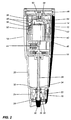
- an electric spice mill 10 has a main body 12 for receiving a power unit 14 and the spice (pepper, salt, etc.) corns to be ground.
- the main body 12 may comprise a top housing 16, a bottom housing 18 and an intermediate shell 20, which may be transparent for allowing a user to see the remaining corns in the spice mill 10. Note that terms such as “top” and “bottom” are used herein when referring to the spice mill 10 in the generally upright position shown in Figure 1 .
- the intermediate shell 20 is slidingly fitted in the bottom housing 18 while the top housing 16 is mounted at one end of the intermediate shell 20.
- the power unit 14 has a casing 40 for receiving a motor 42 connected to a shaft 28 via a transmission unit 44.
- a cover 46 is mounted on the bottom housing 18.
- the top housing 16 receives a grinding unit 22, which has an outer grinding member 24 and an inner grinding member 26 mounted on the shaft 28.
- the inner grinding member 26 has teeth on its outer side and a hole in which the shaft 28 passes.
- the outer grinding member 24 has teeth on its inner side and is fixedly mounted in the bottom housing 18 such that it cannot move or rotate. Hence, the inner grinding member 26 can rotate relative to the outer grinding member 24 for grinding the spice corns when driven by the motor 42 via the shaft 28.
- the inner grinding member 26 is located between a knob 30 and a spring 32 that abuts at one end against small protrusions 34 provided on the shaft 28.
- the knob 30 has an internal threaded portion 36 registering with a threaded portion 38 provided on the shaft 28. It is understood that the distance between the outer and inner grinding members 24, 26 may be adjusted by turning the knob 30. Specifically, by turning the knob 30 in the clockwise direction, the inner grinding member 26 moves closer to the outer grinding member 24, and by turning the knob 30 in the counter-clockwise direction, the inner grinding member 26 moves away from the outer grinding member 24. Hence, the user can choose the desired size of spice particles by turning the knob 30.
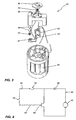
- the power unit 14 has first and second actuators 48, 50 and also comprises a first contact 52 and a first biasing element 54 mounted between the first actuator 48 and first contact 52; and a second contact 56 and a second biasing element 58 mounted between the second actuator 50 and second contact 56.
- the first actuator 48 is a metallic ball as shown in Figures 1 to 3
- the second actuator 50 may be a push button as shown in Figures 1 to 3 and the biasing element 58 may be a spring and the biasing element 54 is a spring as shown in Figures 1 to 3 .
- the power unit 14 also comprises batteries 60 connected to the motor 42. All these components are connected to a switch 62, which is in contact with first and second electric circuits 66, 68 such that the second electric circuit 68 is controlled by the first electric circuit 66.
- the first actuator 48 is capable of opening and closing the first contact 52 located in the first electric circuit 66
- the second actuator 50 is capable of opening and closing the second contact 56 located in the first electric circuit 66
- the first electric circuit 66 also comprises a resistor 64 located between the second contact 56 and switch 62.
- the switch 62 may be a transistor such as a NPN silicon power transistor TIP41C with the following maximum values: a continuous collector current of 6A, a peak collector current of 10A, and a collector-emitter voltage of 100V.
- the batteries 60 and motor 42 are located in the second electric circuit 68.
- the first actuator 48 is movable between a first position wherein the pepper mill is in a generally upright position, as shown in Figure 1 , and a second position wherein the pepper mill is in an upside down, position, as shown in Figure 2 .
- the second position corresponds to a position of the spice mill 10 wherein the user inverts the spice mill 10 such that ground spice particulars can exit from the spice mill 10. In that sense, the second position may correspond to a position wherein the spice mill 10 is inverted at 45° for example.
- the power unit 14 has a first biasing element 54 located between the first actuator 48 and the first contact 52 for absorbing the first actuator 48 such that the first contact 52 is only closed once when the spice mill 10 is moved to the second position.
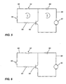
- the first actuator 48 contacts the first contact 52, the first contact 52 is closed as shown in Figure 5 and the first actuator 48 therefore allows a first current i to flow in the first electric circuit 66 and the switch 62 is then responsive to the first current i to allow a second current I to flow in the second electric circuit 68 such that the grinding unit 22 is driven by the motor 42.
- the first and second currents i, I have respective amperages Ai, AI wherein Ai is smaller that AI and the resistor 64 may have a resistance of 8 ohms to 22 ohms.
- Ai is smaller that AI
- the resistor 64 may have a resistance of 8 ohms to 22 ohms.
- the power unit 14 also comprises a second actuator 50 is capable of opening and closing the second contact 56 located in the first electric circuit 66 as shown in Figures 4 to 6 .
- the second actuator 50 may be a push button accessible by the user.
- the second actuator 50 may be a push button that is pressed when the cover 46 is mounted on the main body 12. In that way, because the second actuator 50 is pressed when the cover 46 is mounted on the main body 12, the second actuator 50 contacts the second contact 56 closing it as shown in Figures 4 and 5 .
- the second contact 56 is opened as shown in Figure 6 , and no current flows into the switch 62.
- the cover may also be turnable between first and second positions, wherein, in the first position, the cover presses the second actuator 50 for closing the second contact 52, and in the second position, the cover frees the second actuator 50 for opening the second contact 52.
- the second actuator 50 is pressed for closing the first contact 56.
- the first actuator 48 contacts the first contact 52 such that the first contact 52 is closed. Because both first and second contacts 52, 56 are closed as shown in Figure 5 , a first current i will flow in the first electric circuit 66 and into the switch 62, which will then allow a second electric current I to flow into the second electric circuit 68 and the motor 42, the current I being sufficient such that the grinding unit 22 is driven by the motor 42.
- the spice mill 10 is turned to the first position so that the first actuator 48 is away from the first contact 52, thereby opening the first electric circuit 66, once again preventing flow of current into the switch 62 which in turns does not allow sufficient current flow into the motor 42 to drive the grinding unit 22.
- the cover 46 is removed from the bottom housing 18 of the spice mill 10. Because the second actuator 50 will be depressed once the cover 46 is removed, the second contact 56 will then be opened as shown in Figure 6 and the motor 42 will not receive sufficient current flow to drive the grinding unit 22, irrespective of which position of the spice mill 10 is moved to.
- the power unit 14 is afterwards removed from the main body 12 and the user may then add spice corns into the main body 12.
- the user can mount the power unit 14 on the shaft 28 and the second contact 56 will only be closed when the cover 46 will be mounted again on the bottom housing 18 of the spice mill 10. Then, when the spice mill 10 is turned to the second position, the first actuator 48 contacts the first contact 52 such that the first contact 52 is closed. Because both first and second contacts 52, 56 are closed, a first current i will flow in the first electric circuit 66 and into the switch 62, which will then allow a second electric current I to flow into the second electric circuit 68 and the motor 42, the current I being sufficient such that the grinding unit 22 is driven by the motor 42.
Landscapes
- Engineering & Computer Science (AREA)
- Mechanical Engineering (AREA)
- Food Science & Technology (AREA)
- Seasonings (AREA)
- Food-Manufacturing Devices (AREA)
- Carbon And Carbon Compounds (AREA)
Claims (11)
- Elektrische Gewürzmühle (10) mit:(a) einem Hauptkörper (12) zur Aufnahme von Gewürzkörnern;(b) einem in dem Hauptkörper angebrachten Motor (42);(c) eine Mahleinheit (22) zum Mahlen der Gewürzkörner, wobei die Mahleinheit mit dem Motor verbunden ist und der Motor dazu eingerichtet ist, die Mahleinheit anzutreiben; und(d) einer mit dem Motor verbundenen Antriebseinheit (14),
wobei die Gewürzmühle dadurch gekennzeichnet ist, dass die Antriebseinheit umfasst:(i) eine erste und eine zweite elektrische Schaltung (66, 68), wobei die erste elektrische Schaltung einen ersten und einen zweiten Kontakt (52, 56) umfasst und die zweite elektrische Schaltung (68) den Motor umfasst;(ii) einen Schalter (62), der in elektrischem Kontakt mit der ersten und der zweiten Schaltung steht, wobei die erste elektrische Schaltung ferner einen zwischen dem ersten Kontakt und dem Schalter angeordneten Widerstand (64) umfasst;(iii) einen ersten Aktuator (48), der ein Metallball ist, welcher zwischen einer ersten und einer zweiten Position bewegbar und dazu in der Lage ist, den ersten Kontakt zu öffnen und zu schließen, wobei der Metallball in der ersten Position einen Stromfluss in der ersten elektrischen Schaltung verhindert und der Metallball in der zweiten Position ermöglicht, dass in der ersten elektrischen Schaltung ein erster Strom fließt, und der Schalter in Reaktion auf den ersten Strom in der ersten elektrischen Schaltung ermöglicht, dass in der zweiten elektrischen Schaltung ein zweiter Strom fließt, so dass die Mahleinheit von dem Motor angetrieben wird, und wobei der erste und der zweite Strom eine entsprechende erste und zweite Stromstärke haben, wobei die erste Stromstärke kleiner ist als die zweite Stromstärke; und(iv) eine Feder (54) zwischen dem Metallball und dem ersten Kontakt;und dadurch, dass sie einen zweiten Aktuator (50) umfasst, der dazu in der Lage ist, den zweiten Kontakt (56) zu öffnen und zu schließen, wobei der zweite Aktuator zwischen einer ersten und einer zweiten Position bewegbar ist, und wobei der zweite Aktuator in der ersten Position einen Stromfluss in der ersten elektrischen Schaltung (66) verhindert und der zweite Aktuator in der zweiten Position ermöglicht; dass in der ersten elektrischen Schaltung ein erster Strom fließt. - Elektrische Gewürzmühle nach Anspruch 1,
bei der die erste Stromstärke weniger als 10% der zweiten Stromstärke beträgt. - Elektrische Gewürzmühle nach Anspruch 1 oder 2,
bei der die Mahleinheit (22) über eine Welle (28) mit dem Motor (42) verbunden ist und ein an dem Hauptkörper angebrachtes äußeres Mahlelement (24) sowie ein an einem Ende der Welle angebrachtes inneres Mahlelement (26) umfasst. - Elektrische Gewürzmühle nach einem der Ansprüche 1 bis 3,
bei der der Schalter (62) einen Transistor umfasst. - Elektrische Gewürzmühle nach einem der Ansprüche 1 bis 4,
bei der der Widerstand (64) einen Widerstand zwischen 8 Ohm und 22 Ohm hat. - Elektrische Gewürzmühle nach einem der Ansprüche 1 bis 5,
bei der der Motor (42) unabhängig von der Position, in die die Gewürzmühle bewegt wird, nicht ausreichend Strom erhält, um die Mahleinheit (22) anzutreiben, wenn sich der zweite Aktuator (50) in der ersten Position befindet. - Elektrische Gewürzmühle nach einem der Ansprüche 1 bis 6,
bei der der zweite Aktuator (50) für einen Anwender zugänglich ist. - Elektrische Gewürzmühle nach Anspruch 7,
bei der sich der zweite Aktuator (50) in der zweiten Position befindet, wenn er von einem Anwender gedrückt wird. - Elektrische Gewürzmühle nach einem der Ansprüche 1 bis 6,
die ferner eine Abdeckung (46) umfasst, die an einem Ende des Hauptkörpers benachbart zu dem zweiten Aktuator (50) angebracht ist, wobei sich der zweite Aktuator in der zweiten Position befindet, wenn die Abdeckung an dem Hauptkörper befestigt ist. - Elektrische Gewürzmühle nach einem der Ansprüche 1 bis 6,
die ferner eine Abdeckung (46) umfasst, die an einem Ende des Hauptkörpers benachbart zu dem zweiten Aktuator (50) angebracht ist, wobei sich der zweite Aktuator in der ersten Position befindet, wenn sich die Abdeckung in einer erste Position befindet, und wobei sich der zweite Aktuator in der zweiten Position befindet, wenn sich die Abdeckung in einer zweiten Position befindet. - Elektrische Gewürzmühle nach einem der Ansprüche 1 bis 6,
die ferner eine Abdeckung (46) umfasst, die an einem Ende des Hauptkörpers angebracht ist, wobei der zweite Aktuator (50) ein für einen Anwender zugänglicher Druckknopf ist, und wobei sich der Druckknopf in der zweiten Position befindet, wenn er von dem Anwender gedrückt wird.
Applications Claiming Priority (1)
| Application Number | Priority Date | Filing Date | Title |
|---|---|---|---|
| US11/131,759 US7293728B2 (en) | 2005-05-18 | 2005-05-18 | Electric spice mill |
Publications (2)
| Publication Number | Publication Date |
|---|---|
| EP1723882A1 EP1723882A1 (de) | 2006-11-22 |
| EP1723882B1 true EP1723882B1 (de) | 2009-08-19 |
Family
ID=36922089
Family Applications (1)
| Application Number | Title | Priority Date | Filing Date |
|---|---|---|---|
| EP06290364A Expired - Lifetime EP1723882B1 (de) | 2005-05-18 | 2006-03-02 | Elektrische Gewürzmühle |
Country Status (7)
| Country | Link |
|---|---|
| US (1) | US7293728B2 (de) |
| EP (1) | EP1723882B1 (de) |
| CN (1) | CN1864609A (de) |
| AT (1) | ATE439786T1 (de) |
| AU (1) | AU2006200495A1 (de) |
| CA (1) | CA2532760C (de) |
| DE (1) | DE602006008522D1 (de) |
Cited By (1)
| Publication number | Priority date | Publication date | Assignee | Title |
|---|---|---|---|---|
| EP4382010A1 (de) * | 2022-12-07 | 2024-06-12 | Stefan Eckstein | Kaffeemühle und verfahren zur bedienerfreundlichen fixierung eines mahlwerkes einer solchen |
Families Citing this family (15)
| Publication number | Priority date | Publication date | Assignee | Title |
|---|---|---|---|---|
| US7380737B2 (en) * | 2006-03-22 | 2008-06-03 | Duo Yeu Metal. Col, Ltd. | Electric seasoning mill |
| FR2912634B1 (fr) * | 2007-02-16 | 2009-05-08 | Yienn Lih Entpr Co Ltd | Moulin a poivre electrique |
| GB2447962B (en) * | 2007-03-29 | 2011-08-31 | Yienn Lih Entpr Co Ltd | Electric pepper mill |
| US7874505B1 (en) * | 2007-08-31 | 2011-01-25 | Food Equipment Technologies Company, Inc. | Food grinder with electronically adjustable grind settings, tooless disassembly |
| WO2009047590A1 (en) | 2007-10-12 | 2009-04-16 | Bich Francois | Grinding system, grinding mill for such grinding system and reload cartridge for such grinding system. |
| USD618519S1 (en) | 2008-11-26 | 2010-06-29 | Pi-Design Ag | Condiment mill |
| CN201775519U (zh) * | 2010-08-19 | 2011-03-30 | 张国平 | 一种电动研磨器 |
| USD674672S1 (en) * | 2011-08-18 | 2013-01-22 | Koziol Ideas For Friends Gmbh | Peppermill |
| WO2013106840A1 (en) * | 2012-01-12 | 2013-07-18 | Roberts Daniel James Jr | Spice mill with interchangeable spice containers |
| TWM464117U (zh) * | 2012-12-26 | 2013-11-01 | Yienn Lih Entpr Co Ltd | 電動調味品研磨器 |
| US10694774B2 (en) * | 2016-02-03 | 2020-06-30 | Michael Beck | Automatic grinder |
| US10405700B2 (en) * | 2016-03-09 | 2019-09-10 | Chung-Jen Pai | Grinder |
| CN107321438A (zh) * | 2017-07-14 | 2017-11-07 | 宾信国际有限公司 | 电动磨茶机 |
| USD893961S1 (en) * | 2018-07-26 | 2020-08-25 | Peugeot Saveurs | Spice mill |
| USD873629S1 (en) * | 2018-07-26 | 2020-01-28 | Peugeot Saveurs | Spice mill |
Family Cites Families (9)
| Publication number | Priority date | Publication date | Assignee | Title |
|---|---|---|---|---|
| US3734417A (en) * | 1971-07-20 | 1973-05-22 | J Russell | Electric pepper mill |
| US3912941A (en) * | 1974-04-15 | 1975-10-14 | Thomas M Passarella | Isolation circuit for arc reduction in a dc circuit |
| US4307808A (en) * | 1975-12-03 | 1981-12-29 | Johnson Laurence J | Apparatus for refining herbage |
| US5134255A (en) * | 1991-03-18 | 1992-07-28 | Aerodyne Controls Corporation | Miniature acceleration switch |
| US5675228A (en) | 1995-12-18 | 1997-10-07 | General Electric Company | Methods and apparatus for controlling energization of a motor |
| US6443377B1 (en) | 2001-02-27 | 2002-09-03 | Shun-I Cheng | Pepper mill |
| US6443378B1 (en) | 2001-03-20 | 2002-09-03 | James Huang | Pepper mill |
| US6830205B2 (en) * | 2003-02-11 | 2004-12-14 | Duo Yeu Metal Co., Ltd. | Electric pepper mill |
| US7077347B1 (en) * | 2005-06-02 | 2006-07-18 | Duo Yeu Metal Co., Ltd. | Electric pepper mill |
-
2005
- 2005-05-18 US US11/131,759 patent/US7293728B2/en not_active Expired - Fee Related
-
2006
- 2006-01-11 CA CA002532760A patent/CA2532760C/en not_active Expired - Fee Related
- 2006-02-06 AU AU2006200495A patent/AU2006200495A1/en not_active Abandoned
- 2006-03-02 AT AT06290364T patent/ATE439786T1/de not_active IP Right Cessation
- 2006-03-02 EP EP06290364A patent/EP1723882B1/de not_active Expired - Lifetime
- 2006-03-02 DE DE602006008522T patent/DE602006008522D1/de not_active Expired - Lifetime
- 2006-04-28 CN CNA2006100766745A patent/CN1864609A/zh active Pending
Cited By (1)
| Publication number | Priority date | Publication date | Assignee | Title |
|---|---|---|---|---|
| EP4382010A1 (de) * | 2022-12-07 | 2024-06-12 | Stefan Eckstein | Kaffeemühle und verfahren zur bedienerfreundlichen fixierung eines mahlwerkes einer solchen |
Also Published As
| Publication number | Publication date |
|---|---|
| CA2532760C (en) | 2009-04-14 |
| US7293728B2 (en) | 2007-11-13 |
| AU2006200495A1 (en) | 2006-12-07 |
| EP1723882A1 (de) | 2006-11-22 |
| CN1864609A (zh) | 2006-11-22 |
| US20060261197A1 (en) | 2006-11-23 |
| DE602006008522D1 (de) | 2009-10-01 |
| CA2532760A1 (en) | 2006-11-18 |
| ATE439786T1 (de) | 2009-09-15 |
Similar Documents
| Publication | Publication Date | Title |
|---|---|---|
| CA2532760C (en) | Electric spice mill | |
| US11198229B2 (en) | Hair clippers with flexing electrically adjustable blades | |
| US7604191B2 (en) | Grinder | |
| EP1449471B1 (de) | Verbesserung in einer elektrischen Pfeffermühle | |
| CA3090654C (en) | Electronic grinder | |
| EP0201161B1 (de) | Haushaltsmühle | |
| US9460869B2 (en) | Electric hand tool with activation indication device | |
| US6966507B2 (en) | Electric coffee grinder | |
| EP3554419A1 (de) | Munddusche mit magnetischer befestigung | |
| US20030131480A1 (en) | Hair clipper with turbo-cutting mode | |
| US5455886A (en) | Electrical implement with variable speed control | |
| US20180098493A1 (en) | Powered spool line winding mechanism for string trimmer | |
| JP3890091B2 (ja) | 遮断器 | |
| US6700340B2 (en) | Control circuit for a coffee grinder | |
| CN213551360U (zh) | 一种集成式开关装置以及料理机 | |
| EP3308622B1 (de) | Angetriebene spulenleitungsaufwickeleinrichtung für fadenschneider | |
| CN109821623B (zh) | 电子研磨器 | |
| GB2447962A (en) | Electric pepper mill | |
| CN210299473U (zh) | 一种带振动娱乐功能的香烟盒 | |
| US20260061646A1 (en) | Electric hair cutting device with blade adjustment mechanism | |
| US20250091191A1 (en) | Power tool with multiple actuator configurations | |
| JP6641251B2 (ja) | ダイヤル装置、およびこれを用いた回路遮断器 | |
| CN120155896A (zh) | 电动工具 | |
| JP6601027B2 (ja) | 調理器 | |
| JPH03272528A (ja) | 車両用ハンドルスイッチ |
Legal Events
| Date | Code | Title | Description |
|---|---|---|---|
| PUAI | Public reference made under article 153(3) epc to a published international application that has entered the european phase |
Free format text: ORIGINAL CODE: 0009012 |
|
| AK | Designated contracting states |
Kind code of ref document: A1 Designated state(s): AT BE BG CH CY CZ DE DK EE ES FI FR GB GR HU IE IS IT LI LT LU LV MC NL PL PT RO SE SI SK TR |
|
| AX | Request for extension of the european patent |
Extension state: AL BA HR MK YU |
|
| 17P | Request for examination filed |
Effective date: 20061219 |
|
| 17Q | First examination report despatched |
Effective date: 20070222 |
|
| AKX | Designation fees paid |
Designated state(s): AT BE BG CH CY CZ DE DK EE ES FI FR GB GR HU IE IS IT LI LT LU LV MC NL PL PT RO SE SI SK TR |
|
| GRAP | Despatch of communication of intention to grant a patent |
Free format text: ORIGINAL CODE: EPIDOSNIGR1 |
|
| GRAS | Grant fee paid |
Free format text: ORIGINAL CODE: EPIDOSNIGR3 |
|
| GRAA | (expected) grant |
Free format text: ORIGINAL CODE: 0009210 |
|
| AK | Designated contracting states |
Kind code of ref document: B1 Designated state(s): AT BE BG CH CY CZ DE DK EE ES FI FR GB GR HU IE IS IT LI LT LU LV MC NL PL PT RO SE SI SK TR |
|
| REG | Reference to a national code |
Ref country code: GB Ref legal event code: FG4D |
|
| REG | Reference to a national code |
Ref country code: CH Ref legal event code: EP |
|
| REG | Reference to a national code |
Ref country code: IE Ref legal event code: FG4D |
|
| REF | Corresponds to: |
Ref document number: 602006008522 Country of ref document: DE Date of ref document: 20091001 Kind code of ref document: P |
|
| LTIE | Lt: invalidation of european patent or patent extension |
Effective date: 20090819 |
|
| PG25 | Lapsed in a contracting state [announced via postgrant information from national office to epo] |
Ref country code: SE Free format text: LAPSE BECAUSE OF FAILURE TO SUBMIT A TRANSLATION OF THE DESCRIPTION OR TO PAY THE FEE WITHIN THE PRESCRIBED TIME-LIMIT Effective date: 20090819 Ref country code: LT Free format text: LAPSE BECAUSE OF FAILURE TO SUBMIT A TRANSLATION OF THE DESCRIPTION OR TO PAY THE FEE WITHIN THE PRESCRIBED TIME-LIMIT Effective date: 20090819 Ref country code: IS Free format text: LAPSE BECAUSE OF FAILURE TO SUBMIT A TRANSLATION OF THE DESCRIPTION OR TO PAY THE FEE WITHIN THE PRESCRIBED TIME-LIMIT Effective date: 20091219 Ref country code: ES Free format text: LAPSE BECAUSE OF FAILURE TO SUBMIT A TRANSLATION OF THE DESCRIPTION OR TO PAY THE FEE WITHIN THE PRESCRIBED TIME-LIMIT Effective date: 20091130 Ref country code: FI Free format text: LAPSE BECAUSE OF FAILURE TO SUBMIT A TRANSLATION OF THE DESCRIPTION OR TO PAY THE FEE WITHIN THE PRESCRIBED TIME-LIMIT Effective date: 20090819 Ref country code: AT Free format text: LAPSE BECAUSE OF FAILURE TO SUBMIT A TRANSLATION OF THE DESCRIPTION OR TO PAY THE FEE WITHIN THE PRESCRIBED TIME-LIMIT Effective date: 20090819 |
|
| NLV1 | Nl: lapsed or annulled due to failure to fulfill the requirements of art. 29p and 29m of the patents act | ||
| PG25 | Lapsed in a contracting state [announced via postgrant information from national office to epo] |
Ref country code: NL Free format text: LAPSE BECAUSE OF FAILURE TO SUBMIT A TRANSLATION OF THE DESCRIPTION OR TO PAY THE FEE WITHIN THE PRESCRIBED TIME-LIMIT Effective date: 20090819 Ref country code: SI Free format text: LAPSE BECAUSE OF FAILURE TO SUBMIT A TRANSLATION OF THE DESCRIPTION OR TO PAY THE FEE WITHIN THE PRESCRIBED TIME-LIMIT Effective date: 20090819 Ref country code: PL Free format text: LAPSE BECAUSE OF FAILURE TO SUBMIT A TRANSLATION OF THE DESCRIPTION OR TO PAY THE FEE WITHIN THE PRESCRIBED TIME-LIMIT Effective date: 20090819 Ref country code: LV Free format text: LAPSE BECAUSE OF FAILURE TO SUBMIT A TRANSLATION OF THE DESCRIPTION OR TO PAY THE FEE WITHIN THE PRESCRIBED TIME-LIMIT Effective date: 20090819 |
|
| PG25 | Lapsed in a contracting state [announced via postgrant information from national office to epo] |
Ref country code: BG Free format text: LAPSE BECAUSE OF FAILURE TO SUBMIT A TRANSLATION OF THE DESCRIPTION OR TO PAY THE FEE WITHIN THE PRESCRIBED TIME-LIMIT Effective date: 20091119 Ref country code: CY Free format text: LAPSE BECAUSE OF FAILURE TO SUBMIT A TRANSLATION OF THE DESCRIPTION OR TO PAY THE FEE WITHIN THE PRESCRIBED TIME-LIMIT Effective date: 20090819 Ref country code: PT Free format text: LAPSE BECAUSE OF FAILURE TO SUBMIT A TRANSLATION OF THE DESCRIPTION OR TO PAY THE FEE WITHIN THE PRESCRIBED TIME-LIMIT Effective date: 20091221 |
|
| PG25 | Lapsed in a contracting state [announced via postgrant information from national office to epo] |
Ref country code: EE Free format text: LAPSE BECAUSE OF FAILURE TO SUBMIT A TRANSLATION OF THE DESCRIPTION OR TO PAY THE FEE WITHIN THE PRESCRIBED TIME-LIMIT Effective date: 20090819 Ref country code: DK Free format text: LAPSE BECAUSE OF FAILURE TO SUBMIT A TRANSLATION OF THE DESCRIPTION OR TO PAY THE FEE WITHIN THE PRESCRIBED TIME-LIMIT Effective date: 20090819 Ref country code: CZ Free format text: LAPSE BECAUSE OF FAILURE TO SUBMIT A TRANSLATION OF THE DESCRIPTION OR TO PAY THE FEE WITHIN THE PRESCRIBED TIME-LIMIT Effective date: 20090819 Ref country code: RO Free format text: LAPSE BECAUSE OF FAILURE TO SUBMIT A TRANSLATION OF THE DESCRIPTION OR TO PAY THE FEE WITHIN THE PRESCRIBED TIME-LIMIT Effective date: 20090819 |
|
| PG25 | Lapsed in a contracting state [announced via postgrant information from national office to epo] |
Ref country code: SK Free format text: LAPSE BECAUSE OF FAILURE TO SUBMIT A TRANSLATION OF THE DESCRIPTION OR TO PAY THE FEE WITHIN THE PRESCRIBED TIME-LIMIT Effective date: 20090819 |
|
| PLBE | No opposition filed within time limit |
Free format text: ORIGINAL CODE: 0009261 |
|
| STAA | Information on the status of an ep patent application or granted ep patent |
Free format text: STATUS: NO OPPOSITION FILED WITHIN TIME LIMIT |
|
| PG25 | Lapsed in a contracting state [announced via postgrant information from national office to epo] |
Ref country code: BE Free format text: LAPSE BECAUSE OF FAILURE TO SUBMIT A TRANSLATION OF THE DESCRIPTION OR TO PAY THE FEE WITHIN THE PRESCRIBED TIME-LIMIT Effective date: 20090819 |
|
| 26N | No opposition filed |
Effective date: 20100520 |
|
| PG25 | Lapsed in a contracting state [announced via postgrant information from national office to epo] |
Ref country code: MC Free format text: LAPSE BECAUSE OF NON-PAYMENT OF DUE FEES Effective date: 20100331 Ref country code: GR Free format text: LAPSE BECAUSE OF FAILURE TO SUBMIT A TRANSLATION OF THE DESCRIPTION OR TO PAY THE FEE WITHIN THE PRESCRIBED TIME-LIMIT Effective date: 20091120 |
|
| REG | Reference to a national code |
Ref country code: CH Ref legal event code: PL |
|
| GBPC | Gb: european patent ceased through non-payment of renewal fee |
Effective date: 20100302 |
|
| REG | Reference to a national code |
Ref country code: FR Ref legal event code: ST Effective date: 20101130 |
|
| PG25 | Lapsed in a contracting state [announced via postgrant information from national office to epo] |
Ref country code: FR Free format text: LAPSE BECAUSE OF NON-PAYMENT OF DUE FEES Effective date: 20100331 Ref country code: IE Free format text: LAPSE BECAUSE OF NON-PAYMENT OF DUE FEES Effective date: 20100302 |
|
| PG25 | Lapsed in a contracting state [announced via postgrant information from national office to epo] |
Ref country code: LI Free format text: LAPSE BECAUSE OF NON-PAYMENT OF DUE FEES Effective date: 20100331 Ref country code: CH Free format text: LAPSE BECAUSE OF NON-PAYMENT OF DUE FEES Effective date: 20100331 |
|
| PGFP | Annual fee paid to national office [announced via postgrant information from national office to epo] |
Ref country code: DE Payment date: 20100929 Year of fee payment: 5 |
|
| PG25 | Lapsed in a contracting state [announced via postgrant information from national office to epo] |
Ref country code: IT Free format text: LAPSE BECAUSE OF FAILURE TO SUBMIT A TRANSLATION OF THE DESCRIPTION OR TO PAY THE FEE WITHIN THE PRESCRIBED TIME-LIMIT Effective date: 20090819 Ref country code: GB Free format text: LAPSE BECAUSE OF NON-PAYMENT OF DUE FEES Effective date: 20100302 |
|
| PG25 | Lapsed in a contracting state [announced via postgrant information from national office to epo] |
Ref country code: DE Free format text: LAPSE BECAUSE OF NON-PAYMENT OF DUE FEES Effective date: 20111001 |
|
| REG | Reference to a national code |
Ref country code: DE Ref legal event code: R119 Ref document number: 602006008522 Country of ref document: DE Effective date: 20111001 |
|
| PG25 | Lapsed in a contracting state [announced via postgrant information from national office to epo] |
Ref country code: LU Free format text: LAPSE BECAUSE OF NON-PAYMENT OF DUE FEES Effective date: 20100302 Ref country code: HU Free format text: LAPSE BECAUSE OF FAILURE TO SUBMIT A TRANSLATION OF THE DESCRIPTION OR TO PAY THE FEE WITHIN THE PRESCRIBED TIME-LIMIT Effective date: 20100220 |
|
| PG25 | Lapsed in a contracting state [announced via postgrant information from national office to epo] |
Ref country code: TR Free format text: LAPSE BECAUSE OF FAILURE TO SUBMIT A TRANSLATION OF THE DESCRIPTION OR TO PAY THE FEE WITHIN THE PRESCRIBED TIME-LIMIT Effective date: 20090819 |