EP1723893A2 - Vorrichtung zur Abgabe von Waschmittel, insbesondere für eine Geschirrspülmaschine - Google Patents
Vorrichtung zur Abgabe von Waschmittel, insbesondere für eine Geschirrspülmaschine Download PDFInfo
- Publication number
- EP1723893A2 EP1723893A2 EP06113918A EP06113918A EP1723893A2 EP 1723893 A2 EP1723893 A2 EP 1723893A2 EP 06113918 A EP06113918 A EP 06113918A EP 06113918 A EP06113918 A EP 06113918A EP 1723893 A2 EP1723893 A2 EP 1723893A2
- Authority
- EP
- European Patent Office
- Prior art keywords
- lid
- support structure
- axis
- receptacle
- closed position
- Prior art date
- Legal status (The legal status is an assumption and is not a legal conclusion. Google has not performed a legal analysis and makes no representation as to the accuracy of the status listed.)
- Granted
Links
Images



Classifications
-
- A—HUMAN NECESSITIES
- A47—FURNITURE; DOMESTIC ARTICLES OR APPLIANCES; COFFEE MILLS; SPICE MILLS; SUCTION CLEANERS IN GENERAL
- A47L—DOMESTIC WASHING OR CLEANING; SUCTION CLEANERS IN GENERAL
- A47L15/00—Washing or rinsing machines for crockery or tableware
- A47L15/42—Details
- A47L15/44—Devices for adding cleaning agents; Devices for dispensing cleaning agents, rinsing aids or deodorants
- A47L15/4409—Devices for adding cleaning agents; Devices for dispensing cleaning agents, rinsing aids or deodorants by tipping containers or opening their lids, e.g. with the help of a programmer
Definitions
- This invention concerns a device for distributing a washing agent, in particular for a dishwasher provided with a front door oscillating around a substantially horizontal axis.
- One purpose of this invention is to propose a distributor device which is simple and economical to realize, ergonomically improved, and with safe and reliable operation.
- a device for distributing a washing agent comprising a support structure intended to be fixed to the internal face of the abovementioned door and in which a tub receptacle is defined, operatively turned towards the inside of the machine and suitable for holding a quantity of washing agent, a lid guided in a sliding manner in said structure and manually displaceable, against the action of elastic means of recall, from an open position to a closed position of said receptacle, respectively distant from and close to said axis; and means of retention associated with the lid and suitable for retaining it in the closed position, against the action of said means of recall; the means of recall being fitted in the support structure at one side of said receptacle different from the one closest to said axis and being de-activatable by means of an electrically controlled actuator device, as well as by means of a manually activated release element which is also mounted moveably in the support structure at one side of said receptacle different from the side closest to said axis.
- the abovementioned manually activated release element is fitted moveably in the support structure in a lateral position relative to the path of the lid.
- FIG. 1 As a whole 1 in figure 1 indicates a dishwasher of a type known per se.
- the machine 1 comprises a casing 2, with a substantially parallelepiped form, in which is defined a washing chamber 3 accessible through a front opening face 4 in the casing 2 with which a closing door 5 is associated.
- the door 5 is articulated to the structure of the machine 1 in correspondence with a horizontal axis A-A, at its bottom horizontal side.
- the door 5 is therefore capable of assuming a vertical position in which it recloses the washing chamber 3, and a lowered position, shown in figure 1, in which it permits easy access to a distributor device for washing agents indicated as a whole as 10.
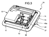
- the distributor device 10 is mounted in the internal face of the door 5 of the machine 1.
- this distributor device 10 is of the type known as integrated, i.e. comprising a single support structure or body 11, in which both a distributor device 12 for a liquid, solid or powder washing agent, and a distributor device 13 for a rinsing or brightening agent are realized.
- the invention is not moreover limited to the implementation of the washing agent distributor device in integrated form with an adjacent distributor device for a rinsing agent.
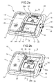
- the shaped body 11 of the washing agent distributor device 12 has two facing walls or sides 14 and 15, with a convex arched external profile. Defined between these facing walls or sides 14, 15 is a lowered area 16 (figures 2a and 2b) in the part of which closest to the A-A axis of articulation of the door is a concave receptacle 17, essentially in the manner of a tub, with an inlet 18 bordered by an edge in relief 19 (figures 2a, 9 and 10).
- the receptacle 17 is intended to hold a quantity of the washing agent which must be distributed during the washing stage of a dishwasher operating cycle.
- the distributor device 12 also comprises a lid 20, mounted in a sliding form between the lateral walls or sides 14 and 15 of the body 11, in a guided manner along an arched trajectory, essentially on a generally cylindrical surface.
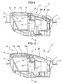
- the lid 20 is mobile in particular from a receptacle 17 open or uncovered position, shown in figures 2a, 4, 6 and 9, to a closed position of this receptacle 17, shown in figures 2b, 8 and 10.
- a hollow 20a usable as a receptacle for holding a quantity of detergent for use in a prewash stage in the dishwasher operating cycle.
- the lid 20 can be moved manually, against the action of elastic means of recall described below, from the open position to the closed position of the receptacle 17, along a substantially curvilinear path, at right angles to the horizontal axis A-A of oscillation of the door 5 of the dishwasher.
- the closed and open positions of the lid 20 are situated at vertically different levels.
- the lid 20 carries out a rotation essentially from the top to the bottom.
- the lid 20 has a respective pair of sliding formations in the manner of protruding pegs 23, 24, staggered with respect to one another along the operating displacement direction of the same with respect to the body 11.
- These grooves are arched, in such a way that they are capable of permitting the displacement of the lid 20 substantially according to an arched trajectory, as has already been said above.
- annular sealing gasket intended, when the lid is in the closed position, to couple with tightness with the edge 12 of the inlet of the tub receptacle 17.
- the guide grooves 25 and 26 are shaped in such a way that their ends operatively nearest the A-A axis of the door 5 of the dishwasher have a sharp deviation of direction 25a at their terminal part.
- the arrangement is such that when the front sliding formations 23 of the lid enter and then pass the deviation of direction 25a of the associated guide grooves 25, the lid 20 carries out a sharp oscillation in its approach to the edge 19 of the washing agent receptacle 17.
- a shaped element indicated as a whole by 30 is mounted revolving around an axis B-B in the structure 11.
- the end of the element 30 turned to the lid 20 has a protruding terminal appendix 31, essentially shaped in L form.
- a recess 32 the cross section of which is essentially in V form, or dihedral, between two walls 33 and 34 essentially parallel to the B-B axis.
- the revolving shaped element 30 also has a transversally protruding appendix or wing 35 (figures 7 and 8) capable of cooperating, in a manner which will be better described below, with a mobile element 36 of an electrically controlled actuator 37.
- the actuator 37 comprises a solenoid or bobbin 38 (figure 7), the excitation of which is capable of provoking an axial displacement of the nucleus 36.
- the latter is coupled with the appendix or wing 35 of the shaped revolving element 30, in such a way that a translation by it (towards the left when looking at figure 7) is capable of provoking a rotation of the element 30 (clockwise when looking at figure 7, anticlockwise when looking at figure 8).
- the shaped terminal element 31 of the revolving element 30 is capable of cooperating with the lid 20 to retain the latter in the closed position, as shown in figure 10.
- the user can make the lid 20 move from the open position (figure 9) to the closed position (figure 10) manually by sliding it along the guide grooves 25.
- the lid 20 (which up to this point had been able to slide without interfering with the formation 31 of the element 30) performs a certain displacement in the direction of the receptacle 17 and the revolving element 30 of a sufficient magnitude to allow that when a part 20b (figures 9 and 10) of its rear edge descends it gets stuck on said formation 31 of the revolving element 30. In this condition, the lid 20 is retained in the closed position.
- an elastic device such as a spring working by torsion, which tends to keep it in the position illustrated in figure 10, the terminal formation 31 of which is suitable for keeping the lid 20 in the closed position.
- the revolving element 30 is capable of being made to revolve around the axis B-B and therefore to leave the position according to figures 8 and 10, following excitation of the electrically controlled actuator 37: in this case the rotation of the element 30 causes a displacement of its terminal formation 31, moving away from the receptacle 17.
- the lid 20 follows this displacement of the terminal appendix 31 of the revolving element 30: initially the lid 20 remains retained, however, by the formation 31 in any case until, having passed the terminal part 25a of the guide grooves 25, the lid 20 moves away from the receptacle 17 to a sufficient extent to permit its bottom edge 20b to clear the abovementioned formation 31 of the element 30. Under the action of elastic means of recall, the lid 20 can then return itself to the open position shown in figure 9.
- the release of the lid 20 from the terminal appendix 31 of the revolving element 30 can also be provoked by a release element indicated overall as 40 in figures 2a, 2b, 4-6 and 8.
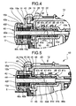
- the release element 40 comprises a head 40a with an essentially cylindrical outer peripheral shell 40b, in which a plurality of openings 40c is obtained (figures 4 and 5).
- Extending from the head 40a is an integral cylindrical axial rod 40d, a terminal distal part 40e of which with a reduced cross section extends into the recess 32 of the revolving element 30, as can be seen in particular in figure 8, in a facing relationship with the wall 33 of this recess.
- respective appendices 15a protruding laterally from the wall 15 of the support body 11 extend with a certain axial play in the openings 40c of the head 40a of the release element.
- These appendices are provided with respective end teeth 15b, with an inclined profile, capable of engaging themselves by snapping into the abovementioned openings 40c.
- the appendices 15a extend between the external shell 40b of the head 40 and a further internal cylindrical shell 40f, coaxial with the first.
- the arrangement described above is such that the release element 40 is axially translatable relative to the support body or structure 11, but is blocked angularly with respect to it.
- the shank or rod 40d of the release element 40 extends to the inside of a shaped tubular body indicated as a whole by 41.
- this body has an initial end part 41a, with an increased diameter, which extends in a revolving manner inside a cylindrical passage 42 in the wall or side 15 of the support body or casing 11.
- the body 41 also comprises a second part 41b, with a relatively reduced diameter, which extends in a revolving manner, but with quite a narrow coupling, in an inner tubular formation 43 of the body 11 of the distributor device.
- a helical spring 44 is arranged between the head 40a of the release element 40 and the part 41a of the tubular body 41.
- This spring 44 works both as a compression spring, and as a torsion spring: on one side this tends to press the release element 40 to the axial position shown in figure 4, as well as to a predetermined angular position.
- the part 41b of the tubular body 41 has two end annular grooves 41c externally, and an intermediate spiral-form groove 41d.
- a viscous material for example a lubricating grease, intended during operation to counter the relative rotation of the body 41 inside this formation.
- the purpose of the arrangement of this viscous material is to create a dampening or deceleration effect on the movement of the lid 20 from the closed position to the open position, with a view to the reduction of operating noise.
- the element 41 adjacent to the shoulder defined between its parts 41a and 41b, has a toothing 45 (figures 4, 5 and 8) which meshes with a corresponding arched rack 46 realized in the bottom part of the side 21 of the lid 20 (in particular see figure 8).
- the arrangement is such that when the user displaces the lid from the open position (figure 2a) to the closed position (figure 2b), the rack 46 of this lid causes a rotation of the tubular body 41. Following this rotation, the helical spring 44 is torsion-loaded.
- the lid 20 Having reached the closed position (figure 2b), the lid 20 is held there following the engagement of its edge 20b with the terminal appendix 31 of the revolving element 30 (figure 10), as already described above.
- the spring 44 then stays torsionally preloaded.
- this release element 40 passes from the axial position of figure 4 to the axial position of figure 5: the spring 44 is also compression-loaded, and the shank 40e of the release element, acting on the surface 33 of the revolving element 30 (figure 8) provokes a rotation of the latter, and this is followed by the release of the lid 20 from the appendix 31 of the element 30, as already better described above, and the return of the lid 20 to the open position (figure 2a and 9) under the action of the spring 44 which discharges its own torsional preload.
- the displacement of the lid 20 towards the open position is effectively commanded by the tubular body 41 which is driven in rotation by the spring 44, and by the toothing 45 of the latter which is coupled with the rack 46 of the lid.
- the input into its seat of the abovementioned viscous material can be realized conveniently through two passages 47 and 48 provided in the wall of the tubular formation 43, and then subsequently closed tight, for example by means of a sealing material, or by heat-sealing.
- One of these passages is used in effect for inputting viscous material into the seat, while the other permits the air to escape.
- the release element 40 can be realized in such a way as to be able to rotate around its axis in the manner of a knob, relatively to the support structure 11 of the distributor device, to provoke a corresponding rotation of the revolving element 30 around the axis B-B and therefore determine the release of the lid 20 from the closed position.
Landscapes
- Washing And Drying Of Tableware (AREA)
Priority Applications (1)
| Application Number | Priority Date | Filing Date | Title |
|---|---|---|---|
| PL06113918T PL1723893T3 (pl) | 2005-05-16 | 2006-05-15 | Urządzenie do rozprowadzania środka myjącego, w szczególności do zmywarki |
Applications Claiming Priority (1)
| Application Number | Priority Date | Filing Date | Title |
|---|---|---|---|
| IT000331A ITTO20050331A1 (it) | 2005-05-16 | 2005-05-16 | Dispositivo per l'erogazione di un agente di lavaggio, particolarmente pe una macchina lavastoviglie |
Publications (3)
| Publication Number | Publication Date |
|---|---|
| EP1723893A2 true EP1723893A2 (de) | 2006-11-22 |
| EP1723893A3 EP1723893A3 (de) | 2007-11-28 |
| EP1723893B1 EP1723893B1 (de) | 2009-12-02 |
Family
ID=36942857
Family Applications (1)
| Application Number | Title | Priority Date | Filing Date |
|---|---|---|---|
| EP06113918A Not-in-force EP1723893B1 (de) | 2005-05-16 | 2006-05-15 | Vorrichtung zur Abgabe von Waschmittel, insbesondere für eine Geschirrspülmaschine |
Country Status (5)
| Country | Link |
|---|---|
| EP (1) | EP1723893B1 (de) |
| DE (1) | DE602006010760D1 (de) |
| ES (1) | ES2337387T3 (de) |
| IT (1) | ITTO20050331A1 (de) |
| PL (1) | PL1723893T3 (de) |
Cited By (7)
| Publication number | Priority date | Publication date | Assignee | Title |
|---|---|---|---|---|
| WO2007116354A3 (en) * | 2006-04-07 | 2007-12-21 | Elbi Int Spa | Device for dispensing a washing agent in a washing machine, particularly a dishwasher |
| WO2008080799A1 (en) * | 2006-12-29 | 2008-07-10 | Arcelik Anonim Sirketi | A dishwasher |
| EP1989988A1 (de) * | 2007-05-09 | 2008-11-12 | Elbi International SPA | Spendervorrichtung für ein Wasch- und/oder Spülmittel in einem Geschirrspüler mit verbessertem Mechanismus für manuelle Öffnung |
| EP2138088A1 (de) * | 2008-06-26 | 2009-12-30 | CANDY S.p.A. | Abgabevorrichtung für Reinigungsmitteltabletten für Geschirrspülmaschine |
| CN102665521A (zh) * | 2009-12-02 | 2012-09-12 | 埃尔比国际有限公司 | 用于在清洗机特别是洗碗机中分配洗涤剂的分配机 |
| US20140196754A1 (en) * | 2013-01-14 | 2014-07-17 | Bsh Home Appliances Corporation | Dispenser optimization for easier closing |
| EP3335615A1 (de) * | 2016-12-15 | 2018-06-20 | Illinois Tool Works Inc. | Geschirrspülmittelspender mit verringerter lärmentwicklung |
Families Citing this family (1)
| Publication number | Priority date | Publication date | Assignee | Title |
|---|---|---|---|---|
| CN110604530B (zh) * | 2018-06-15 | 2022-10-04 | 青岛海尔洗碗机有限公司 | 一种用于洗碗机的洗涤剂添加器及洗碗机 |
Family Cites Families (5)
| Publication number | Priority date | Publication date | Assignee | Title |
|---|---|---|---|---|
| US3419190A (en) * | 1966-10-27 | 1968-12-31 | Gen Electric | Treating agent dispensing means for automatic washing machine |
| DE19548105A1 (de) * | 1995-12-21 | 1997-06-26 | Bosch Siemens Hausgeraete | Vorrichtung zur Zugabe von Reinigungsmitteln, insbesondere für Geschirrspülmaschinen |
| ITTO20010078A1 (it) * | 2001-01-26 | 2002-07-26 | Eltek Spa | Dispositivo dispensatore di agenti di lavaggio per una macchina di lavaggio domestica, in particolare una lavastoviglie. |
| ITTO20010204U1 (it) * | 2001-10-31 | 2003-04-30 | Elbi Int Spa | Dispositivo erogatore di detersivo,particolarmente per una macchina lavastoviglie. |
| ITTO20011103A1 (it) * | 2001-11-26 | 2003-05-26 | Eltek Spa | Dispositivo dispensatore, particolarmente per macchine lavastoviglie. |
-
2005
- 2005-05-16 IT IT000331A patent/ITTO20050331A1/it unknown
-
2006
- 2006-05-15 ES ES06113918T patent/ES2337387T3/es active Active
- 2006-05-15 EP EP06113918A patent/EP1723893B1/de not_active Not-in-force
- 2006-05-15 DE DE602006010760T patent/DE602006010760D1/de active Active
- 2006-05-15 PL PL06113918T patent/PL1723893T3/pl unknown
Cited By (13)
| Publication number | Priority date | Publication date | Assignee | Title |
|---|---|---|---|---|
| US8499773B2 (en) | 2006-04-07 | 2013-08-06 | Elbi International S.P.A. | Device for dispensing a washing agent in a washing machine, particularly a dishwasher |
| WO2007116354A3 (en) * | 2006-04-07 | 2007-12-21 | Elbi Int Spa | Device for dispensing a washing agent in a washing machine, particularly a dishwasher |
| WO2008080799A1 (en) * | 2006-12-29 | 2008-07-10 | Arcelik Anonim Sirketi | A dishwasher |
| EP1989988A1 (de) * | 2007-05-09 | 2008-11-12 | Elbi International SPA | Spendervorrichtung für ein Wasch- und/oder Spülmittel in einem Geschirrspüler mit verbessertem Mechanismus für manuelle Öffnung |
| EP2138088A1 (de) * | 2008-06-26 | 2009-12-30 | CANDY S.p.A. | Abgabevorrichtung für Reinigungsmitteltabletten für Geschirrspülmaschine |
| CN102665521B (zh) * | 2009-12-02 | 2015-11-25 | 埃尔比国际有限公司 | 用于在清洗机中分配洗涤剂的分配机 |
| CN102665521A (zh) * | 2009-12-02 | 2012-09-12 | 埃尔比国际有限公司 | 用于在清洗机特别是洗碗机中分配洗涤剂的分配机 |
| US20140196754A1 (en) * | 2013-01-14 | 2014-07-17 | Bsh Home Appliances Corporation | Dispenser optimization for easier closing |
| US9474435B2 (en) * | 2013-01-14 | 2016-10-25 | Bsh Home Appliances Corporation | Dispenser optimization for easier closing |
| DE102013226985B4 (de) | 2013-01-14 | 2023-02-02 | BSH Hausgeräte GmbH | Reinigungsmittelzugabe mit vereinfachter Schließfunktion |
| EP3335615A1 (de) * | 2016-12-15 | 2018-06-20 | Illinois Tool Works Inc. | Geschirrspülmittelspender mit verringerter lärmentwicklung |
| US20180168423A1 (en) * | 2016-12-15 | 2018-06-21 | Illinois Tool Works Inc. | Dishwasher Detergent Dispenser with Reduced Noise |
| US10660500B2 (en) | 2016-12-15 | 2020-05-26 | Illinois Tool Works Inc. | Dishwasher detergent dispenser with reduced noise |
Also Published As
| Publication number | Publication date |
|---|---|
| EP1723893A3 (de) | 2007-11-28 |
| ITTO20050331A1 (it) | 2006-11-17 |
| DE602006010760D1 (de) | 2010-01-14 |
| EP1723893B1 (de) | 2009-12-02 |
| PL1723893T3 (pl) | 2010-04-30 |
| ES2337387T3 (es) | 2010-04-23 |
Similar Documents
| Publication | Publication Date | Title |
|---|---|---|
| EP2506751B1 (de) | Waschmittelspender für eine haushaltwaschmaschine, insbesondere eine geschirrspülmaschine | |
| KR101064697B1 (ko) | 도어용 힌지장치 | |
| EP2405790B1 (de) | Maschine zur zubereitung von getränken durch aufgiessen unter verwendung von patronen | |
| KR101343915B1 (ko) | 가전 제품 도어의 싱글 힌지 댐핑 장치 | |
| EP1723893B1 (de) | Vorrichtung zur Abgabe von Waschmittel, insbesondere für eine Geschirrspülmaschine | |
| JP6611828B2 (ja) | 家具用ヒンジ | |
| US20060226750A1 (en) | Refrigerator having home bar | |
| KR102401707B1 (ko) | 세탁기 | |
| EP2007268A2 (de) | Vorrichtung zur ausgabe eines waschmittels in einer waschmaschine, insbesondere einer geschirrspülmaschine | |
| EP3592195B1 (de) | Vorrichtung zur abgabe von waschmitteln für eine waschmaschine, insbesondere eine geschirrspülmaschine | |
| CN110279368A (zh) | 分配器和洗涤电器 | |
| SI23269A (sl) | Sestav šarnirja in blažilnika | |
| CN110279369A (zh) | 分配器和洗涤电器 | |
| ITTO20070062U1 (it) | Dispositivo erogatore per un agente di lavaggio e/o di risciacquo, particolarmente per una macchina lavastoviglie e dotato di meccanismo di apertura manuale perfezionato | |
| EP3135180A1 (de) | Geschirrspülmaschine mit einer gel-dosiereinheit | |
| KR102492945B1 (ko) | 도어 자동 개폐 장치 | |
| EP2918215B1 (de) | Geschirrspülmaschine mit Reinigungsmittelspender | |
| KR101756197B1 (ko) | 도어 클로저 | |
| KR101334958B1 (ko) | 냉장고용 물탱크 및 이를 포함하는 제빙장치 | |
| ES2746906T3 (es) | Bisagra, particularmente para un aparato electrodoméstico | |
| EP1920100B1 (de) | Betätigungsorgan und verfahren | |
| JP7319285B2 (ja) | 筐体壁に形成された開口部を覆う覆い板を有する抽出飲料用飲料調製機 | |
| CN217244243U (zh) | 一种洗涤剂分配器及清洗机 | |
| KR102767618B1 (ko) | 가전제품 도어락 장치 | |
| KR20110080020A (ko) | 얼음보관함 어셈블리 및 이를 구비하는 냉장고 |
Legal Events
| Date | Code | Title | Description |
|---|---|---|---|
| PUAI | Public reference made under article 153(3) epc to a published international application that has entered the european phase |
Free format text: ORIGINAL CODE: 0009012 |
|
| AK | Designated contracting states |
Kind code of ref document: A2 Designated state(s): AT BE BG CH CY CZ DE DK EE ES FI FR GB GR HU IE IS IT LI LT LU LV MC NL PL PT RO SE SI SK TR |
|
| AX | Request for extension of the european patent |
Extension state: AL BA HR MK YU |
|
| RIN1 | Information on inventor provided before grant (corrected) |
Inventor name: MARONE, GIUSEPPE |
|
| PUAL | Search report despatched |
Free format text: ORIGINAL CODE: 0009013 |
|
| AK | Designated contracting states |
Kind code of ref document: A3 Designated state(s): AT BE BG CH CY CZ DE DK EE ES FI FR GB GR HU IE IS IT LI LT LU LV MC NL PL PT RO SE SI SK TR |
|
| AX | Request for extension of the european patent |
Extension state: AL BA HR MK YU |
|
| 17P | Request for examination filed |
Effective date: 20080528 |
|
| 17Q | First examination report despatched |
Effective date: 20080620 |
|
| AKX | Designation fees paid |
Designated state(s): DE ES FR PL TR |
|
| GRAP | Despatch of communication of intention to grant a patent |
Free format text: ORIGINAL CODE: EPIDOSNIGR1 |
|
| GRAS | Grant fee paid |
Free format text: ORIGINAL CODE: EPIDOSNIGR3 |
|
| GRAA | (expected) grant |
Free format text: ORIGINAL CODE: 0009210 |
|
| AK | Designated contracting states |
Kind code of ref document: B1 Designated state(s): DE ES FR PL TR |
|
| REF | Corresponds to: |
Ref document number: 602006010760 Country of ref document: DE Date of ref document: 20100114 Kind code of ref document: P |
|
| REG | Reference to a national code |
Ref country code: ES Ref legal event code: FG2A Ref document number: 2337387 Country of ref document: ES Kind code of ref document: T3 |
|
| REG | Reference to a national code |
Ref country code: PL Ref legal event code: T3 |
|
| PLBE | No opposition filed within time limit |
Free format text: ORIGINAL CODE: 0009261 |
|
| STAA | Information on the status of an ep patent application or granted ep patent |
Free format text: STATUS: NO OPPOSITION FILED WITHIN TIME LIMIT |
|
| 26N | No opposition filed |
Effective date: 20100903 |
|
| PGFP | Annual fee paid to national office [announced via postgrant information from national office to epo] |
Ref country code: TR Payment date: 20140501 Year of fee payment: 9 Ref country code: ES Payment date: 20140526 Year of fee payment: 9 |
|
| PGFP | Annual fee paid to national office [announced via postgrant information from national office to epo] |
Ref country code: PL Payment date: 20140403 Year of fee payment: 9 |
|
| PGFP | Annual fee paid to national office [announced via postgrant information from national office to epo] |
Ref country code: DE Payment date: 20140731 Year of fee payment: 9 |
|
| PGFP | Annual fee paid to national office [announced via postgrant information from national office to epo] |
Ref country code: FR Payment date: 20140602 Year of fee payment: 9 |
|
| REG | Reference to a national code |
Ref country code: DE Ref legal event code: R119 Ref document number: 602006010760 Country of ref document: DE |
|
| REG | Reference to a national code |
Ref country code: FR Ref legal event code: ST Effective date: 20160129 |
|
| PG25 | Lapsed in a contracting state [announced via postgrant information from national office to epo] |
Ref country code: DE Free format text: LAPSE BECAUSE OF NON-PAYMENT OF DUE FEES Effective date: 20151201 |
|
| PG25 | Lapsed in a contracting state [announced via postgrant information from national office to epo] |
Ref country code: FR Free format text: LAPSE BECAUSE OF NON-PAYMENT OF DUE FEES Effective date: 20150601 |
|
| REG | Reference to a national code |
Ref country code: ES Ref legal event code: FD2A Effective date: 20160629 |
|
| PG25 | Lapsed in a contracting state [announced via postgrant information from national office to epo] |
Ref country code: ES Free format text: LAPSE BECAUSE OF NON-PAYMENT OF DUE FEES Effective date: 20150516 |
|
| PG25 | Lapsed in a contracting state [announced via postgrant information from national office to epo] |
Ref country code: PL Free format text: LAPSE BECAUSE OF NON-PAYMENT OF DUE FEES Effective date: 20150515 |
|
| PG25 | Lapsed in a contracting state [announced via postgrant information from national office to epo] |
Ref country code: TR Free format text: LAPSE BECAUSE OF NON-PAYMENT OF DUE FEES Effective date: 20150515 |