EP1724001A2 - Equipement de réaction interface liquide/liquide - Google Patents
Equipement de réaction interface liquide/liquide Download PDFInfo
- Publication number
- EP1724001A2 EP1724001A2 EP06009673A EP06009673A EP1724001A2 EP 1724001 A2 EP1724001 A2 EP 1724001A2 EP 06009673 A EP06009673 A EP 06009673A EP 06009673 A EP06009673 A EP 06009673A EP 1724001 A2 EP1724001 A2 EP 1724001A2
- Authority
- EP
- European Patent Office
- Prior art keywords
- liquid
- substrate
- grooves
- liquid interface
- channel
- Prior art date
- Legal status (The legal status is an assumption and is not a legal conclusion. Google has not performed a legal analysis and makes no representation as to the accuracy of the status listed.)
- Withdrawn
Links
Images


Classifications
-
- B—PERFORMING OPERATIONS; TRANSPORTING
- B01—PHYSICAL OR CHEMICAL PROCESSES OR APPARATUS IN GENERAL
- B01L—CHEMICAL OR PHYSICAL LABORATORY APPARATUS FOR GENERAL USE
- B01L3/00—Containers or dishes for laboratory use, e.g. laboratory glassware; Droppers
- B01L3/50—Containers for the purpose of retaining a material to be analysed, e.g. test tubes
- B01L3/502—Containers for the purpose of retaining a material to be analysed, e.g. test tubes with fluid transport, e.g. in multi-compartment structures
- B01L3/5027—Containers for the purpose of retaining a material to be analysed, e.g. test tubes with fluid transport, e.g. in multi-compartment structures by integrated microfluidic structures, i.e. dimensions of channels and chambers are such that surface tension forces are important, e.g. lab-on-a-chip
- B01L3/502769—Containers for the purpose of retaining a material to be analysed, e.g. test tubes with fluid transport, e.g. in multi-compartment structures by integrated microfluidic structures, i.e. dimensions of channels and chambers are such that surface tension forces are important, e.g. lab-on-a-chip characterised by multiphase flow arrangements
- B01L3/502776—Containers for the purpose of retaining a material to be analysed, e.g. test tubes with fluid transport, e.g. in multi-compartment structures by integrated microfluidic structures, i.e. dimensions of channels and chambers are such that surface tension forces are important, e.g. lab-on-a-chip characterised by multiphase flow arrangements specially adapted for focusing or laminating flows
-
- B—PERFORMING OPERATIONS; TRANSPORTING
- B01—PHYSICAL OR CHEMICAL PROCESSES OR APPARATUS IN GENERAL
- B01J—CHEMICAL OR PHYSICAL PROCESSES, e.g. CATALYSIS OR COLLOID CHEMISTRY; THEIR RELEVANT APPARATUS
- B01J19/00—Chemical, physical or physico-chemical processes in general; Their relevant apparatus
- B01J19/0093—Microreactors, e.g. miniaturised or microfabricated reactors
-
- B—PERFORMING OPERATIONS; TRANSPORTING
- B01—PHYSICAL OR CHEMICAL PROCESSES OR APPARATUS IN GENERAL
- B01J—CHEMICAL OR PHYSICAL PROCESSES, e.g. CATALYSIS OR COLLOID CHEMISTRY; THEIR RELEVANT APPARATUS
- B01J19/00—Chemical, physical or physico-chemical processes in general; Their relevant apparatus
- B01J19/24—Stationary reactors without moving elements inside
- B01J19/248—Reactors comprising multiple separated flow channels
- B01J19/249—Plate-type reactors
-
- G—PHYSICS
- G01—MEASURING; TESTING
- G01N—INVESTIGATING OR ANALYSING MATERIALS BY DETERMINING THEIR CHEMICAL OR PHYSICAL PROPERTIES
- G01N1/00—Sampling; Preparing specimens for investigation
- G01N1/28—Preparing specimens for investigation including physical details of (bio-)chemical methods covered elsewhere, e.g. G01N33/50, C12Q
- G01N1/38—Diluting, dispersing or mixing samples
-
- B—PERFORMING OPERATIONS; TRANSPORTING
- B01—PHYSICAL OR CHEMICAL PROCESSES OR APPARATUS IN GENERAL
- B01J—CHEMICAL OR PHYSICAL PROCESSES, e.g. CATALYSIS OR COLLOID CHEMISTRY; THEIR RELEVANT APPARATUS
- B01J2219/00—Chemical, physical or physico-chemical processes in general; Their relevant apparatus
- B01J2219/00781—Aspects relating to microreactors
- B01J2219/00783—Laminate assemblies, i.e. the reactor comprising a stack of plates
-
- B—PERFORMING OPERATIONS; TRANSPORTING
- B01—PHYSICAL OR CHEMICAL PROCESSES OR APPARATUS IN GENERAL
- B01J—CHEMICAL OR PHYSICAL PROCESSES, e.g. CATALYSIS OR COLLOID CHEMISTRY; THEIR RELEVANT APPARATUS
- B01J2219/00—Chemical, physical or physico-chemical processes in general; Their relevant apparatus
- B01J2219/24—Stationary reactors without moving elements inside
- B01J2219/2401—Reactors comprising multiple separate flow channels
- B01J2219/245—Plate-type reactors
- B01J2219/2451—Geometry of the reactor
- B01J2219/2453—Plates arranged in parallel
-
- B—PERFORMING OPERATIONS; TRANSPORTING
- B01—PHYSICAL OR CHEMICAL PROCESSES OR APPARATUS IN GENERAL
- B01J—CHEMICAL OR PHYSICAL PROCESSES, e.g. CATALYSIS OR COLLOID CHEMISTRY; THEIR RELEVANT APPARATUS
- B01J2219/00—Chemical, physical or physico-chemical processes in general; Their relevant apparatus
- B01J2219/24—Stationary reactors without moving elements inside
- B01J2219/2401—Reactors comprising multiple separate flow channels
- B01J2219/245—Plate-type reactors
- B01J2219/2451—Geometry of the reactor
- B01J2219/2456—Geometry of the plates
- B01J2219/2458—Flat plates, i.e. plates which are not corrugated or otherwise structured, e.g. plates with cylindrical shape
-
- B—PERFORMING OPERATIONS; TRANSPORTING
- B01—PHYSICAL OR CHEMICAL PROCESSES OR APPARATUS IN GENERAL
- B01J—CHEMICAL OR PHYSICAL PROCESSES, e.g. CATALYSIS OR COLLOID CHEMISTRY; THEIR RELEVANT APPARATUS
- B01J2219/00—Chemical, physical or physico-chemical processes in general; Their relevant apparatus
- B01J2219/24—Stationary reactors without moving elements inside
- B01J2219/2401—Reactors comprising multiple separate flow channels
- B01J2219/245—Plate-type reactors
- B01J2219/2451—Geometry of the reactor
- B01J2219/2456—Geometry of the plates
- B01J2219/246—Perforated plates
-
- B—PERFORMING OPERATIONS; TRANSPORTING
- B01—PHYSICAL OR CHEMICAL PROCESSES OR APPARATUS IN GENERAL
- B01J—CHEMICAL OR PHYSICAL PROCESSES, e.g. CATALYSIS OR COLLOID CHEMISTRY; THEIR RELEVANT APPARATUS
- B01J2219/00—Chemical, physical or physico-chemical processes in general; Their relevant apparatus
- B01J2219/24—Stationary reactors without moving elements inside
- B01J2219/2401—Reactors comprising multiple separate flow channels
- B01J2219/245—Plate-type reactors
- B01J2219/2476—Construction materials
- B01J2219/2483—Construction materials of the plates
- B01J2219/2485—Metals or alloys
-
- B—PERFORMING OPERATIONS; TRANSPORTING
- B01—PHYSICAL OR CHEMICAL PROCESSES OR APPARATUS IN GENERAL
- B01J—CHEMICAL OR PHYSICAL PROCESSES, e.g. CATALYSIS OR COLLOID CHEMISTRY; THEIR RELEVANT APPARATUS
- B01J2219/00—Chemical, physical or physico-chemical processes in general; Their relevant apparatus
- B01J2219/24—Stationary reactors without moving elements inside
- B01J2219/2401—Reactors comprising multiple separate flow channels
- B01J2219/245—Plate-type reactors
- B01J2219/2476—Construction materials
- B01J2219/2483—Construction materials of the plates
- B01J2219/2487—Ceramics
-
- B—PERFORMING OPERATIONS; TRANSPORTING
- B01—PHYSICAL OR CHEMICAL PROCESSES OR APPARATUS IN GENERAL
- B01J—CHEMICAL OR PHYSICAL PROCESSES, e.g. CATALYSIS OR COLLOID CHEMISTRY; THEIR RELEVANT APPARATUS
- B01J2219/00—Chemical, physical or physico-chemical processes in general; Their relevant apparatus
- B01J2219/24—Stationary reactors without moving elements inside
- B01J2219/2401—Reactors comprising multiple separate flow channels
- B01J2219/245—Plate-type reactors
- B01J2219/2476—Construction materials
- B01J2219/2483—Construction materials of the plates
- B01J2219/2488—Glass
-
- B—PERFORMING OPERATIONS; TRANSPORTING
- B01—PHYSICAL OR CHEMICAL PROCESSES OR APPARATUS IN GENERAL
- B01L—CHEMICAL OR PHYSICAL LABORATORY APPARATUS FOR GENERAL USE
- B01L2200/00—Solutions for specific problems relating to chemical or physical laboratory apparatus
- B01L2200/06—Fluid handling related problems
- B01L2200/0636—Focussing flows, e.g. to laminate flows
-
- B—PERFORMING OPERATIONS; TRANSPORTING
- B01—PHYSICAL OR CHEMICAL PROCESSES OR APPARATUS IN GENERAL
- B01L—CHEMICAL OR PHYSICAL LABORATORY APPARATUS FOR GENERAL USE
- B01L2300/00—Additional constructional details
- B01L2300/08—Geometry, shape and general structure
- B01L2300/0809—Geometry, shape and general structure rectangular shaped
- B01L2300/0816—Cards, e.g. flat sample carriers usually with flow in two horizontal directions
Definitions
- the present invention relates to a liquid/liquid interface reaction equipment in which two kinds of liquids are made to flow at a minute flow rate, the flows of these liquids are made to come together to form a liquid/liquid interface of two-layer flow, and two kinds of liquids are made to react at this liquid/liquid interface.
- This liquid/liquid interface reaction equipment is used in synthesis of, e.g., chemicals, cosmetics, chemical seasonings, and paints.
- fine grooves or holes are formed by machining at the surface of a substrate (chip) that is made of glass, silicon, plastics, ceramics, metals, and the like, and a cover plate is brought in direct contact with the surface of this substrate to cover the grooves, letting the grooves channels of liquids, as well as letting the holes feed ports or collection ports. Further, in the cover plate adhered to the substrate surface, a plurality of through holes in communication with the liquid feed ports and the liquid collection port are formed by machining.
- the channel system consists of two liquid channels through which two kinds of liquids flow individually, and a combined channel in which those two liquid channels are intersected to join.
- liquids are fed individually into respective liquid feed ports with, e.g., a micro-pump, micro-cylinder, or micro-valve.
- Two liquids having been fed into the liquid feed ports flow through respective liquid channels to join on the downstream side. Further, two-layer flow of liquid/liquid interface is formed in the combined channel, and the reaction between two kinds of liquids gets on at this liquid/liquid interface.
- reaction-stopping solution for example, by adding a reaction-stopping solution to these liquids, or cooling the liquids, the reaction is stopped, and the liquid including reaction products is made to flow out from the trailing edge of the combined channel, and to discharge through the liquid collection port.
- the present invention was made in view of the above-described situations, and has an object of providing a liquid/liquid interface reaction equipment with which in the case where different individual channels are made to intersect to join and a laminar flow of liquid/liquid interface is formed in this combined channel to make the reaction of different kinds of liquids, by making an angle at which different individual channels are intersected as small as possible, it is possible to suppress abrupt changes in flow rate or in flow direction when different kinds of liquids are joined, and to prevent the production of solids and thus the occurrence of clogging in the channels.
- the invention as defined in claim 1 is a liquid/liquid interface reaction equipment in which different kinds of liquids are made to flow in different individual channels respectively, the mentioned different individual channels are met each other on the way to form a liquid/liquid interface of laminar flow in a combined channel, and the mentioned different kinds of liquids are reacted with each other at this liquid/liquid interface;
- the liquid/liquid interface reaction equipment being characterized in that there are formed grooves at the front face and the back face of a substrate respectively, and these grooves form the mentioned different individual channels; and that the sum of depth dimensions of each of the mentioned grooves that are formed at the front face and at the back face of the substrate respectively is made larger than a thickness dimension of the substrate; as well as these grooves are intersected in plan view to cause the mentioned different individual channels to meet each other in thickness direction of the substrate.
- the invention as defined in claim 2 is a liquid/liquid interface reaction equipment in which different kinds of liquids are made to flow in different individual channels respectively, the mentioned different individual channels are met each other on the way to form a liquid/liquid interface of laminar flow in a combined channel, and the mentioned different kinds of liquids are reacted with each other at this liquid/liquid interface;
- the liquid/liquid interface reaction equipment being characterized in that there are formed grooves at the front face and the back face of a substrate respectively, and these grooves form the mentioned different individual channels; and that the groove depth of one or both of the mentioned grooves that are formed at the front face and at the back face of the substrate respectively is made to be larger by degrees in downward direction; and these grooves are intersected in thickness direction of the substrate to cause the mentioned different individual channels to meet each other.
- the invention as defined in claim 3 is the liquid/liquid interface reaction equipment according to claim 1 or 2, the liquid/liquid interface reaction equipment being characterized in that plural pieces of the mentioned substrates are stacked to be in direct contact so that said grooves are positioned to be overlapped in plan view between the substrates respectively.
- the invention as defined in claim 4 is the liquid/liquid interface reaction equipment according to claim 3, the liquid/liquid interface reaction equipment being characterized in that at the faces of the adjacent substrates in direct contact, a groove that is formed at the front face of one substrate and a groove that is formed at the back face of the other substrate are intersected on the way to join the individual channel of one substrate and the individual channel of the other substrate.
- the invention as defined in claim 5 is the liquid/liquid interface reaction equipment according to claim 3, the liquid/liquid interface reaction equipment being characterized in that at the faces of the adjacent substrates in direct contact, a groove that is formed at the back face of one substrate and a groove that is formed at the front face of the other substrate are positioned to be overlapped in plan view, as well as a groove that is formed at the front face of one substrate and a groove that is formed at the back face of the other substrate are positioned to be overlapped in plan view.
- the invention as defined in claim 6 is a liquid/liquid interface reaction equipment in which different kinds of liquids are made to flow in different individual channels respectively, the mentioned different individual channels are met each other on the way to form a liquid/liquid interface of laminar flow in a combined channel, and the mentioned different kinds of liquids are reacted with each other at this liquid/liquid interface, the liquid/liquid interface reaction equipment being characterized in that at least one groove is formed at the front face and the back face of a substrate respectively to form the mentioned different individual channels with these grooves; as well as these grooves are intersected to cause the mentioned different individual channels to meet each other in thickness direction of the substrate; and that plural pieces of the mentioned substrates are stacked to be in direct contact so that the mentioned grooves are positioned to be overlapped each other in plan view between the substrates.
- the invention as defined in claim 7 is the liquid/liquid interface reaction equipment according to claim 6, the liquid/liquid interface reaction equipment being characterized in that the sum of depth dimensions of each of the mentioned grooves that are formed at the front face and at the back face of the substrate respectively is made larger than the thickness dimension of the substrate, and the mentioned grooves are intersected in plan view to cause the mentioned different individual channels to meet each other in thickness direction of the substrate.
- the invention as defined in claim 8 is the liquid/liquid interface reaction equipment according to claim 7, the liquid/liquid interface reaction equipment being characterized in that at the faces of the adjacent substrates in direct contact, a groove that is formed at the front face of one substrate and a groove that is formed at the back face of the other substrate are intersected on the way to join an individual channel of one substrate and an individual channel of the other substrate.
- the invention as defined in claim 9 is the liquid/liquid interface reaction equipment according to claim 6, the liquid/liquid interface reaction equipment being characterized in that the groove depth of one or both of the mentioned grooves that are formed at the front face and at the back face of a substrate respectively is made larger by degrees in downward direction, these grooves are intersected in thickness direction of the substrate to cause the mentioned different individual channels to meet each other, and plural pieces of the mentioned substrates are stacked with the front faces and the back faces opposed respectively in alternate order.
- the invention as defined in claim 10 is a liquid/liquid interface reaction equipment in which different kinds of liquids are made to flow in different individual channels respectively, the mentioned different individual channels are met each other on the way to form a liquid/liquid interface of laminar flow in a combined channel, and the mentioned different kinds of liquids are reacted with each other at this liquid/liquid interface, the liquid/liquid interface reaction equipment being characterized in that grooves are formed at one face of two substrates respectively to form the mentioned different individual channels with these grooves, as well as two substrates are brought in direct contact so that the faces at which the grooves are formed are opposed, and these grooves are intersected in plan view to join the mentioned different individual channels; and that plural pieces of substrates in sets of the mentioned two substrates are stacked to be in direct contact.
- the invention as defined in claim 11 is the liquid/liquid interface reaction equipment according to any one of claims 1 through 10, the liquid/liquid interface reaction equipment being characterized in that at least one set of grooves that form different individual channels though which the mentioned different kinds of liquids flow respectively are formed in at least one side of the substrate, each of the mentioned grooves is intersected to cause the mentioned different individual channels to meet each other in one side of the substrate, a liquid/liquid interface of laminar flow is formed in this one side combined channel, and the mentioned different kinds of liquids are reacted with each other at this liquid/liquid interface as well.
- the sum of depth dimensions of each of the grooves that are formed at the front face and at the back face of the substrate respectively is made larger than a thickness dimension of the substrate; and these grooves are intersected in plan view to cause different individual channels of respective channels to meet each other in thickness direction of the substrate. Consequently, being different from the structure in which two grooves that are formed only at the front face of a substrate are intersected in the same plane as in the conventional equipment, an angle at which different individual channels are intersected (angle in a plane orthogonal to a liquid/liquid interface formed by different kinds of liquids being joined) can be substantially 0°
- the groove depth of one or both of the grooves that are formed at the front face and at the back face of the substrate respectively is made to be larger by degrees in downward direction; and these grooves are intersected in thickness direction of the substrate to cause the mentioned different individual channels of respective grooves to meet each other. Consequently, as compared with the structure in which two grooves that are formed only at the front face of the substrate are intersected in the same plane as in the conventional equipment, it is possible to make an angle at which different individual channels are intersected extremely small.
- liquid/liquid interface reaction equipment of the invention according to claim 4, a liquid/liquid interface is formed in a combined channel even between the adjacent substrates in direct contact, and the reaction between different kinds of liquids is made at this liquid/liquid interface. Consequently, it is possible to obtain a large amount of reaction products at one time.
- a groove that is formed at the front face of one of adjacent substrates and a groove that is formed at the back face of the other substrate are intersected at the faces in direct contact, and thus an individual channel of one substrate and an individual channel of the other substrate are joined at the faces in direct contact. Therefore, an angle at which these different individual channels are intersected (angle in a plane orthogonal to a liquid/liquid interface formed by different kinds of liquids being joined) is substantially 0° . As a result, it is possible to suppress abrupt changes in flow rate or in flow direction when different kinds of liquids are joined, and to prevent the production of solids and thus the occurrence of clogging in the channels.
- an angle at which different individual channels are intersected is substantially 0° .
- a groove that is formed at the front face of one of adjacent substrates and a grove that is formed at the back face of the other substrate are intersected at the faces in direct contact, and thus an individual channel of one substrate and an individual channel of the other substrate are joined at the faces in direct contact. Therefore, an angle at which these different individual channels are intersected (angle in a plane orthogonal to a liquid/liquid interface formed by different kinds of liquids being joined) is 0° . As a result, it is possible to suppress abrupt changes in flow rate or in flow direction when different kinds of liquids are joined, and to prevent the production of solids and thus the occurrence of clogging in the channels.
- liquid/liquid interface reaction equipment of the invention In the liquid/liquid interface reaction equipment of the invention according to claim 11, different individual channels meet each other also in one side of a substrate, a liquid/liquid interface of laminar flow is formed in this one side combined channel, and different kinds of liquids are reacted at this liquid/liquid interface as well. As a result, it is possible to obtain a large amount of reaction products at one time.
- Figs. 1 to 4 shows one embodiment according to the invention.
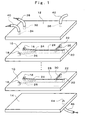
- Fig. 1 is an exploded perspective view showing the schematic construction of main parts of a liquid/liquid interface reaction equipment
- Fig. 2 is a plan view showing a channel construction of a substrate (chip), being a structural element of this equipment.
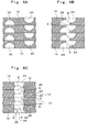
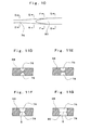
- Figs. 3A, 3B, and 3C are a partially enlarged cross sectional view taken along the arrowed line A-A, partially enlarged cross sectional view taken along the arrowed line B ⁇ B, and partially enlarged cross sectional view taken along the arrowed line C-C of Fig. 2.
- Fig. 4A, 4B, and 4C are partially enlarged cross sectional views in the state in which the substrates are stacked, being the cross sectional views in positions corresponding to along the lines A-A, B-B, and C-C of Fig. 2.
- An essential part of this liquid/liquid reaction equipment is a laminated construction of one or plural pieces of substrates 10 (plural pieces in the illustrated example), an upper cover plate 12 in direct contact with the front face of the substrate 10 (the front face of the substrate in the uppermost position when plural pieces of substrates 10 are stacked as in the illustrated example), and a lower cover plate 14 in direct contact with the back face of the substrate 10 (the back face of the substrate 10 in the lowermost position when plural pieces of substrates 10 are stacked as in the illustrated example).
- the upper cover plate 12 and the substrate 10, between the substrates 10, and the substrate 10 and the lower cover plate 14 are brought in direct contact in the liquid-tight state with each other using fastenings, not shown, forming an integral whole consisting of the upper cover plate 12, plural pieces of substrates 10, and the lower cover plate 14.
- a substrate 10 is made of glass, silicon, plastics, ceramics, metals, and the like. There are formed in the substrate 10 four minute through holes, and these minute through holes act as a first liquid feed port 16, a second liquid feed port 18, a liquid collection port 20, and a reaction stopping solution feed port 22.
- a fine bottomed groove of which one end (leading edge) communicates with the first liquid feed port 16 is formed at the front face of the substrate 10, and this bottomed groove forms a first individual channel 24.
- a fine bottomed groove of which one end (leading edge) communicates with the second liquid feed port 18 is formed at the back face of the substrate 10, and this bottomed groove forms a second individual channel 26.
- the first individual channel 24 and the second individual channel 26 are formed so as to intersect on the way, and to be overlapped each other on the downstream side from the intersection in plan view. Furthermore, the first individual channel 24 and the second individual channel 26 are made to be larger in depth dimension of respective bottomed grooves forming these channels than half the thickness dimension of the substrate 10. Therefore, the sum of depth dimensions of two bottomed grooves is larger than the thickness dimension of the substrate 10.
- the first individual channel 24 and the second individual channel 26 are separate channels independent of each other on the upstream side from the intersection as shown in Fig. 3A. As shown in Fig. 3B, however, the first individual channel 24 and the second individual channel 26 are brought in communication with each other to come together at the intersection, and a communication width comes to be larger by degrees in downstream direction.
- a communication width becomes the maximum on the downstream side from the intersection where the first individual channel 24 and the second individual channel 26 are overlapped with each other in plan view, a through groove is formed with two grooves at the front and back of the substrate 10, and this through groove forms a combined channel 28.
- a trailing edge of this combined channel 28 communicates with the liquid collection port 20.
- a fine bottomed groove of which one end (leading edge) communicates with the reaction stopping solution feed port 22, and of which other end (trailing edge) communicates with the combined channel 28.
- This bottomed groove forms a channel 30 of the reaction stopping solution.
- the first individual channel 24 and the second individual channel 26 of each substrate 10 are separate channels independent of each other on the upstream side from the intersection.
- the first individual channel 24 and the second individual channel 26 are brought in communication with each other to join at each substrate 10, and a communication width comes to be larger by degrees in downstream direction as described above.
- the second individual channel 26 of the substrate 10 on the upper side, and the first individual channel 24 of the substrate 10 on the lower side are brought in communication with each other to join, and a communication width comes to be larger by degrees in downstream direction.
- a communication width comes to be larger by degrees in downstream direction.
- each communication width becomes the maximum, through grooves are formed with two grooves at the front and back of respective substrates 10 are formed, and these through grooves form the combined channels 28 respectively.
- the combined channels 28 are brought in communication with each other between the substrates adjacent to each other in the laminated direction to form a combined channel including a large channel cross section over the entire laminate of plural pieces of substrates 10.
- the upper cover plate 12 and the lower cover plate 14 are made of, e.g., stainless steel or plastics respectively.
- Three minute through holes are formed in the upper cover plate 12. These minute through holes act as a first liquid feed passage 32, a second liquid feed passage 34, and a reaction stopping solution feed passage 36.
- a first liquid feed tube 38, a second liquid feed tube 40, and a reaction stopping solution feed tube 42 are connected in communication respectively.
- the first liquid feed passage 32, the second liquid feed passage 34 and the reaction stopping solution feed passage 36 are brought in communication with the first liquid feed port 16, the second liquid feed port 18, and the reaction stopping solution feed port 22 respectively.
- one minute through hole is formed in the lower cover plate 14, and this minute through hole acts as a liquid discharge passage 44.
- a liquid discharge tube 46 is connected in communication.
- the liquid discharge passage 44 will be brought in communication with the liquid collection port 20 of the substrate 10.
- a first liquid and a second liquid for example, two kinds of an organic solvent and water are put individually into the first liquid feed port 16 and the second liquid feed port 18 of the substrate 10 through the first liquid feed passage 32 and the second liquid feed passage 34 of the upper cover plate 12 respectively using a micro-syringe, micro-pump, micro-valve, or the like.
- the first liquid and the second liquid having been put in respective liquid feed ports 16 and 18 flow in the first individual channel 24 and the second individual channel 26 of the substrate 10 respectively, are joined at the intersection of the first individual channel 24 and the second individual channel 26, and flow in a laminar flow state respectively in the combined channel 28.
- a liquid/liquid interface S of two-layer flow is formed in the combined channel 28, and the reaction between ingredients in the first liquid and ingredients in the second liquid gets on at this liquid/liquid interface S. Furthermore, when plural pieces of substrates 10 are stacked, between the substrates adjacent to each other in the laminated direction, the second liquid flowing in the second individual channel 24 of the upper side substrate 10, and the first liquid flowing in the first individual channel 24 of the lower side substrate 10 are joined at the intersection of the second individual channel 26 and the first individual channel 24, and flow in the laminar flow states respectively in the combined channel 28. As shown in Fig. 4C, then, a liquid/liquid interface S' is formed in the combined channel 28, and the reaction between ingredients in the second liquid and ingredients in the first liquid gets on as well.
- the first individual channel 24 and the second individual channel 26 of the substrate 10 are joined in thickness direction of the substrate 10, so that an angle at which these individual channels 24 and 26 are intersected (angle in a plane orthogonal to the liquid/liquid interface S) is approximately 0° .
- the second individual channel 26 of the upper side substrate 10 and the first individual channel 24 of the lower side substrate 10 are joined in thickness direction of the substrate 10, so that an angle at which these individual channels 26 and 24 are intersected (angle in a plane orthogonal to the liquid/liquid interface S') is 0°. Accordingly, abrupt changes in flow rate or in flow direction when the first and second liquids are joined are suppressed, preventing the production of solids and thus the occurrence of clogging in the channels.
- plural pieces of substrates 10 having the same construction are stacked.
- a substrate 10 including the mentioned construction and a substrate 10' including the construction symmetric with respect to this substrate 10, and plural pieces of these alternately stacked substrates 10 and 10' are stacked to be in direct contact with the front faces thereof and the back faces thereof are opposed to each other.
- liquid/liquid interface reaction equipment of such construction as are shown partially enlarged cross sectional views in positions corresponding to along the lines A-A, B-B, and C-C of Fig. 2 in Figs.
- the second individual channel 26 of the upper side substrate 10 and the second individual channel 26 of the lower side substrate 10' are mutually in communication; and the first individual channel 24 of the upper side substrate 10' and the first individual channel 24 of the lower side substrate 10 are mutually in communication.
- the first individual channel 24' and the second individual channel 26' including double the channel cross-sections respectively.
- the first individual channel 24 and the second individual channel 26, as shown in Fig. 6A are separate channels independent of each other on the upstream side from the intersection; as shown in Fig.
- first individual channel 24 and the second individual channel 26 are intersected at an acute angle in plan view.
- a first individual channel 50 and a second individual channel 52 to be formed in a substrate 48 are formed to be arch-shaped in plan view respectively, and a combined channel 54 is extended in direction of a tangent line of each of the individual channels 50 and 52.
- pressure loss comes to be smaller, thus enabling the smooth interface reaction.
- Reference numerals 56, 58 in Fig. 7 designate a first liquid feed port and a second liquid feed port
- numeral 60 designates a liquid collection port.
- the cross sectional shapes of each of the individual channel 24, 26 are ellipses respectively.
- the cross sectional shapes of the first individual channel 64 and the second individual channel 66 that are formed in a substrate 62 are ovals, or any other cross sectional shape respectively.
- Figs. 9 to 11 show another embodiment according to the invention.
- Fig. 9 is a plan view showing the channel construction of a substrate, being a structural element of the liquid/liquid interface reaction equipment.
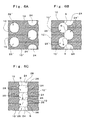
- Fig. 10 is an enlarged plan view of O part of Fig. 9.
- Figs. 11D-11G are a partially enlarged cross sectional view taken along the arrowed line D-D, a partially enlarged cross sectional view taken along the arrowed line E-E, a partially enlarged cross sectional view taken along the arrowed line F-F, and a partially enlarged cross sectional view taken along the arrowed line G-G.
- a substrate 68 of this equipment there are formed three minute through holes acting as a first liquid feed port 70, a second liquid feed port 72, and a liquid collection port 74.
- a first individual channel 76 of a fine bottomed groove of which one end (leading edge) communicates with the first liquid feed port 70 is formed.
- a second individual channel 78 of a fine bottomed groove of which one end (leading edge) communicates with the second liquid feed port 72 is formed.
- the first individual channel 76 and the second individual channel 78 are formed so as to be overlapped each other on the way in plan view.
- first individual channel 76 and the second individual channel 78 are formed so as to be larger in channel cross section in downstream direction at the O part of Fig. 9 as shown in Figs. 10 and Figs. 11D-11G. That is, the bottomed grooves that form the first individual channel 76 and the second individual channel 78 are respectively smaller in depth dimension than half the thickness dimension of the substrate 68 on the upstream side of the O part. However, the depth dimensions (also width dimensions) become larger in downstream direction, and the depth dimensions become larger than half the thickness dimension of the substrate 68 on the downstream side of the O part. Therefore, the sum of depth dimensions of two bottomed grooves becomes larger than the thickness dimension of the substrate 68.
- first individual channel 76 and the second individual channel 78 are separate channels independent of each other on the upstream side of the O part side, as shown in Fig. 11E, the bottoms thereof come closer to each other by degrees in the downstream direction; as shown in Fig. 11F, shortly the bottoms communicate with each other; and as shown in Fig. 11G, a communication width becomes the maximum on the more downstream side of the O part to form a through groove with two grooves at the front and back of the substrate 68, and this through groove forms a combined channel 80.
- the trailing edge of this combined channel 80 communicates with a liquid collection port 60.
- the first liquid and the second liquid having been put in the liquid feed ports 70 and 72 flow separately in the first individual channel 76 and the second individual channel 78 respectively, are joined at the intersection of the first individual channel 76 and the second individual channel 78, and flow in the laminar states respectively in the combine channel 80.
- a liquid/liquid interface S of two-layer flow is formed in the combined channel 80, and the reaction between ingredients in the first liquid and ingredients in the second liquid gets on.
- the first individual channel 76 and the second individual channel 78 are intersected in thickness direction of the substrate 68 to be joined, and the combined channel 80 is formed.
- a substrate 68 including the mentioned construction and a substrate 68' including the construction symmetric with respect to this substrate 168, and that plural pieces of alternately stacked substrates 68 and 68' are stacked to be in direct contact with the front faces thereof and the back faces thereof are opposed to each other respectively.
- liquid/liquid interface reaction equipment of such construction as are shown partially enlarged cross sectional views in positions corresponding to along the lines D-D, E-E, F-F, and G-G of Fig. 10 in Figs.
- Figs. 14 to 17 show a further embodiment according to the invention that includes a construction different from those as mentioned above.
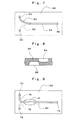
- Fig. 14 is a plan view showing a channel construction of a substrate, being a structural element of the liquid/liquid interface reaction equipment.
- Fig. 15 is a plan view showing the state in which two pieces of substrates are overlapped.
- Figs. 16H, 16I, and 16J are a partially enlarged cross sectional view taken along the arrowed line H-H, a partially enlarged cross sectional view taken along the arrowed line I-I, and a partially enlarged cross sectional view taken along the arrowed line J-J.
- Figs. 17H, 17I, 17J are partially enlarged cross sectional views in the state in which the substrates are stacked, being cross sectional views in positions corresponding to along the line H-H, the line I-I, and the line J-J of Fig. 15.
- two pieces of substrates 82a and 82b are overlapped to form a first individual channel 84, a second individual channel 86, and a combined channel 88.
- both of the substrates 82a and 82b have the same construction, a bottomed groove that is formed at the front face of one substrate 82a forms the first individual channel 84, and a bottomed groove that is formed at the front face of the other substrate 82b forms the second individual channel 86.
- two pieces of substrates 82a and 82b are brought in direct contact with the front faces at which the bottomed grooves are formed opposed to each other to form the combined channel 88.
- first liquid feed port 90 There are formed in one substrate 82a three minute through holes, and these minute through holes act as a first liquid feed port 90, a second liquid feed port 92, and a liquid collection port 94 respectively.
- One end (leading edge) of the first individual channel 84 communicates with the first liquid feed port 90.
- the other substrate 82b three minute through holes, and these minute through holes act as the first liquid feed port 90, the second liquid feed port 92, and the liquid collection port 94 respectively.
- One end (leading edge) of the second individual channel 86 communicates with the second liquid feed port 92.
- the first individual channel 84 and the second individual channel 86 when two pieces of substrates 82a and 82b are brought in direct contact, as shown in Fig.
- the first individual channel 84 and the second individual channel 86 are separate channels independent of each other on the upstream side from the intersection as shown in Fig. 16H.
- the first and second individual channels are brought in communication with each other to join at the intersection, and a communication width comes to be larger by degrees in downstream direction.
- the communication width becomes the maximum to form the combined channel 88. The trailing edge of this combined channel 88 communicates with the liquid collection port 94.
- the first liquid and the second liquid having been put in respective liquid feed ports 90 and 92 flow separately in the first individual channel 84 and the second individual channel 86 respectively; the first individual channel 84 and the second individual channel 86 are intersected in plan view to join; and the first liquid and the second liquid flow in the laminar states respectively in the combined channel 88.
- a liquid/liquid interface S of two-layer flow is formed in the combined channel 88, and the reaction between ingredients in the first liquid and ingredients in the second liquid gets on at this liquid/liquid interface S.
- first individual channel 84 and the second individual channel 86 are joined at the faces where two pieces of substrates 82a and 82b are in direct contact, so that an angle at which both of the individual channels 84 and 86 are intersected (angle in a plan orthogonal to the liquid/liquid interface S) is 0° . Consequently, abrupt changes in flow rate or in flow direction when the first and second liquids are joined are suppressed, preventing the production of solids and thus the occurrence of clogging in the channels.
- plural pieces of substrates can be constructed to stack in direct contact in sets of the substrates 82a and 82b integrally adhered as mentioned above.
- a liquid/liquid interface S of two-layer flow is formed in the combined channel 88 as mentioned above, and the reaction between ingredients in the first liquid and ingredients in the second liquid gets on at this liquid/liquid interface S.
- the first individual channel through which the first liquid flows is formed at the front face of a substrate, and the second individual channel through which the second liquid flows is formed at the back face of the substrate respectively; or the first individual channel through which the first liquid flows is formed at one face on the opposed side of one substrate of one set of substrates to be overlapped each other is formed, and the second individual channel through which the second liquid flows at one face on the opposed side of the other substrate is formed.
- the first individual channel and the second individual channel are made to join in one face of the substrate to from a laminar flow of liquid/liquid interface is formed in this combined channel, and the first liquid and the second liquid are made to react with each other also at this liquid/liquid interface.
- Fig. 18 or 21 Such an embodiment is shown in Fig. 18 or 21.
- Fig. 18 is a plan view showing the channel construction of a substrate (chip), being a structural element of the liquid/liquid interface reaction equipment.
- Figs. 19K, 19L, 19M and 19N, and Figs. 20K, 20L, 20M and 20N are partially enlarged cross sectional views taken along the arrowed line K-K, partially enlarged cross sectional views taken along the arrowed line L-L, partially enlarged cross sectional views taken along the arrowed line M-M, and partially enlarged cross sectional views taken along the arrowed line N-N.
- the first liquid and the second liquid flowing through the channels are shown with different fills.
- Fig. 19K to 19N the first liquid and the second liquid flowing through the channels are shown with different fills.
- Fig. 19K to 19N the first liquid and the second liquid flowing through the channels are shown with different fills.
- Fig. 19K to 19N the first liquid and the second liquid flowing through the channels are shown with different fills.
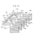
- Fig. 21 is a partially perspective view showing the structure of the channels.
- Fig. 21 omits the illustration of plural pieces of substrates or cover plates to show only the channels, and shows just the channels only at one face (front face) of the substrate to omit the illustration of the channels at the other face (back face) of the substrate.
- This liquid/liquid interface reaction equipment is constructed of one or plural pieces of substrates 100, an upper cover plate, and a lower cover plate, a first liquid feed tube, a second liquid feed tube, and a liquid discharge tube.
- the first liquid feed ports 102a and the second liquid feed ports 102b that are located at the upper half in Fig.
- first liquid feed ports 104a and the second liquid feed ports 104b that are located at the lower half in Fig. 18 are disposed at regular intervals alternately, as well as disposed in reverse order with respect to the first liquid feed ports 102a and the second liquid feed ports 102b at the upper half.
- first individual channels 108a and the second individual channels 108b of fine bottomed grooves of which one ends (leading edges) communicate with the first liquid feed ports 102a and the second liquid feed ports 102b respectively.
- back face of the substrate 100 plural sets (three sets in the illustrated example) of the first individual channels 110a and the second individual channels 110b of fine bottomed grooves of which one ends (leading edges) communicate with the first liquid feed ports 104a and the second liquid feed ports 104b respectively.
- the first individual channels 108a and the second individual channels 108b that are formed on the front face side of the substrate 100, and the first individual channels 110a and the second individual channels 110b that are formed on the back face side of the substrate 100 are disposed so as not to be overlapped at all with each other in plan view. Therefore, as shown in Figs. 19K and 19L, the first individual channels 108a and the second individual channels 108b, and the first individual channels 110a and the second individual channels 110b are separate channels independent of each other. Further, three sets of the first individual channels 108a and the second individual channels 108b that are formed at the front face of the substrate 100 communicate with one front-side combined channel 112 of a wide bottomed groove. Moreover, three sets of the first individual channels 110a and the second individual channels 110b that are formed at the back face of the substrate 100 communicate with one backside combined channel 114 of a wide bottomed groove.
- the front-side combined channel 112 and backside combined channel 114 are formed so as to intersect on the way to be overlapped each other on the downstream side from the intersection thereof. Furthermore, the first individual channels 108a and 110a and the second individual channels 108b and 110b, as well as the front-side combined channel 112 and the backside combined channel 114 are constructed to be larger in depth dimension of each of the bottomed grooves thereof than half the thickness dimension of the substrate 100. Therefore, the sum of depth dimensions of each bottomed groove that is formed at the front face of the substrate 100, and each bottomed groove that is formed at the back face of the substrate 100 is larger than the thickness dimension of the substrate 100.
- the front-side combined channel 112 and the backside combined channel 114 are separate channels independent of each other on the upstream side from the intersection, as shown in Fig. 19M, they are partially in communication with each other to join at the intersection, and a communication width comes to be larger by degrees in downstream direction.
- the communication width becomes the maximum to form a through groove with two groove at the front and back of the substrate 100, and this through groove forms a front-back combined channel 116.
- the trailing edge of this front-back combined channel 116 communicates with a liquid collection port 106.
- the illustration of a reaction stopping solution feed port or a reaction stopping liquid channel, or a cooler as an alternative thereof is omitted.
- first liquid feed ports 102a (104a) and the second liquid feed ports 102b (104b) it is preferable to be of the following channel structure.
- this channel structure for example, as shown in Fig.
- a flat board (not shown) in which a branch channel 118 causing the first liquid to be branched to flow and a branch channel 120 causing the second liquid to be branched to flow are formed respectively, is superimposed on a substrate 100; the first liquid and the second liquid to be fed through a first liquid feed passage 122 and a second liquid feed passage 124 are branched to flow by means of each of the branch channels 118 and 120 respectively; and the first liquid is made to flow from each of the branch channels 118 to each of the first liquid feed ports 102a respectively, as well as the second liquid is made to flow from each of the branch channels 120 to each of the second liquid feed ports 102b respectively.
- the first liquid and the second liquid having been put in the first liquid feed ports 102a and the second liquid feed ports 102b, as shown in Figs. 20K and 20L, flow separately in the first individual channels 108a and the second individual channels 108b respectively, are joined at the portion where the first individual channels 108a and the second individual channels 108b are intersected at an acute angle, and flow in the laminar flow states respectively in the front-side combined channel 112.
- Fig. 20K and 20L flow separately in the first individual channels 108a and the second individual channels 108b respectively, are joined at the portion where the first individual channels 108a and the second individual channels 108b are intersected at an acute angle, and flow in the laminar flow states respectively in the front-side combined channel 112.
- a liquid/liquid interface S1 between the laminar flows is formed in the front-side combined channel 112, and the reaction between ingredients in the first liquid and ingredients in the second liquid gets on at this liquid/liquid interface S1.
- the first liquid and the second liquid having been put in the first liquid feed ports 104a and the second liquid feed ports 104b, as shown in Figs. 20K and 20L, flow separately in the first individual channels 110a and the second individual channels 110b respectively, are joined at the portion where the first individual channels 110a and the second individual channels 110b are intersected at an acute angle, and flow in the laminar flow states respectively in the backside combined channel 114.
- a liquid/liquid interface S2 between the laminar flows is formed in the backside combined channel 114, and the reaction between ingredients in the first liquid and ingredients in the second liquid gets on at this liquid/liquid interface S2.
- first liquid and the second liquid having flowed separately in the laminar flow states in the front-side combined channel 112 and the backside combined channel 114 of the substrate 100 respectively are joined at the portion where the front-side combined channel 112 and the backside combined channel 114 are intersected, and flow in the laminar flow states respectively in the front-back combined channel 116.
- a liquid/liquid interface S3 between the upper and lower laminar flows is formed in the front-back combined channel 116, and the reaction between ingredients in the first liquid and ingredients in the second liquid gets on also at this liquid/liquid interface S3.
- the angle, which the first individual channel 108a makes with the second individual channel 108b on the front side of the substrate, and the angle, which the first individual channel 110a makes with the second individual channel 110b on the backside of the substrate 100 to be as small as possible, abrupt changes in flow rate or in flow direction when both the first and second liquids are joined are suppressed, suppressing the production of solids and thus the occurrence of clogging in the channels.
- the front-side combined channel 112 and the backside combined channel 114 are joined in thickness direction of the substrate 100, so that an angle at which these combined channels 112 and 114 are intersected (angle in a plane orthogonal to a liquid/liquid interface S3) will be substantially 0° . Consequently, abrupt changes in flow rate or in flow direction when both the first and second liquids are joined are suppressed, suppressing the production of solids and thus the occurrence of clogging in the channels.
- the first liquid and the second liquid flow in the laminar flow state respectively in the front-back combined channel 116, and the reaction between ingredients in the first liquid and ingredients in the second liquid is stopped in the vicinity of the trailing end of the front-back combined channel 116. Thereafter, the liquid including reaction products flows out of the trailing edge of the front-back combined channel 116, and is discharged through the liquid collection port 106. Moreover, in this substrate 100, the liquid/liquid interface S3 between upper and lower laminar flows is formed in the front-back combined channel 116; as well as the liquid/liquid interfaces S1 and S2 between laminar flows are formed also in the front-side combined channel and the backside combined channel 114.
Landscapes
- Chemical & Material Sciences (AREA)
- Health & Medical Sciences (AREA)
- Chemical Kinetics & Catalysis (AREA)
- General Health & Medical Sciences (AREA)
- Analytical Chemistry (AREA)
- Organic Chemistry (AREA)
- Immunology (AREA)
- General Physics & Mathematics (AREA)
- Physics & Mathematics (AREA)
- Pathology (AREA)
- Biochemistry (AREA)
- Life Sciences & Earth Sciences (AREA)
- Dispersion Chemistry (AREA)
- Hematology (AREA)
- Clinical Laboratory Science (AREA)
- Physical Or Chemical Processes And Apparatus (AREA)
- Automatic Analysis And Handling Materials Therefor (AREA)
- Micromachines (AREA)
Applications Claiming Priority (2)
| Application Number | Priority Date | Filing Date | Title |
|---|---|---|---|
| JP2005142055 | 2005-05-16 | ||
| JP2006038791A JP2006346671A (ja) | 2005-05-16 | 2006-02-16 | 液液界面反応装置 |
Publications (2)
| Publication Number | Publication Date |
|---|---|
| EP1724001A2 true EP1724001A2 (fr) | 2006-11-22 |
| EP1724001A3 EP1724001A3 (fr) | 2008-01-23 |
Family
ID=36917305
Family Applications (1)
| Application Number | Title | Priority Date | Filing Date |
|---|---|---|---|
| EP06009673A Withdrawn EP1724001A3 (fr) | 2005-05-16 | 2006-05-10 | Equipement de réaction interface liquide/liquide |
Country Status (3)
| Country | Link |
|---|---|
| US (1) | US20060275184A1 (fr) |
| EP (1) | EP1724001A3 (fr) |
| JP (1) | JP2006346671A (fr) |
Cited By (2)
| Publication number | Priority date | Publication date | Assignee | Title |
|---|---|---|---|---|
| EP2384810A4 (fr) * | 2009-01-13 | 2013-10-09 | Kobe Steel Ltd | Réacteur et procédé de fabrication de réacteur |
| EP2377606A4 (fr) * | 2009-01-13 | 2013-10-09 | Kobe Steel Ltd | Réacteur et procédé de fabrication de réacteur |
Families Citing this family (19)
| Publication number | Priority date | Publication date | Assignee | Title |
|---|---|---|---|---|
| US7343784B2 (en) * | 2005-06-28 | 2008-03-18 | Paavo Kinnunen | Method and device for forming a liquid—liquid interface, especially for surface tension measurement |
| JP4686683B2 (ja) * | 2006-05-24 | 2011-05-25 | 国立大学法人京都大学 | 血漿分離用マイクロ流路 |
| JP4970959B2 (ja) * | 2007-01-09 | 2012-07-11 | 株式会社神戸製鋼所 | 反応装置及び反応方法 |
| JP5553428B2 (ja) * | 2008-08-27 | 2014-07-16 | Nsマテリアルズ株式会社 | ペプチドポリマーの製造方法 |
| US8192703B2 (en) | 2009-01-13 | 2012-06-05 | Kobe Steel, Ltd. | Reactor and reacting method |
| US8142741B2 (en) * | 2009-01-13 | 2012-03-27 | Kobe Steel, Ltd. | Reactor and method for manufacturing reactor |
| JP5642488B2 (ja) | 2010-10-04 | 2014-12-17 | 株式会社神戸製鋼所 | 流路構造体 |
| JP2012120962A (ja) * | 2010-12-07 | 2012-06-28 | Kobe Steel Ltd | 流路構造体 |
| JP5547120B2 (ja) * | 2011-03-18 | 2014-07-09 | 株式会社神戸製鋼所 | 流路構造体、流体の混合方法、抽出方法及び反応方法 |
| JP6057251B2 (ja) * | 2011-11-11 | 2017-01-11 | 国立研究開発法人産業技術総合研究所 | 粒子分別装置および粒子分別方法 |
| CN102631959B (zh) * | 2012-04-19 | 2014-09-17 | 南京大学 | 实现血浆持续分离的微流控器件及其分离方法 |
| EP3207980A4 (fr) * | 2014-10-14 | 2018-07-04 | Alps Electric Co., Ltd. | Dispositif de mélange de fluides |
| JP2017148796A (ja) * | 2016-02-24 | 2017-08-31 | 東芝機械株式会社 | マイクロミキサー、マイクロミキサーエレメントおよびその製造方法 |
| JP7196916B2 (ja) * | 2018-06-29 | 2022-12-27 | 株式会社ニコン | 流体デバイス及びシステム |
| JP7070679B2 (ja) * | 2018-06-29 | 2022-05-18 | 株式会社ニコン | 流体デバイス及びシステム並びに混合方法 |
| WO2020100943A1 (fr) * | 2018-11-14 | 2020-05-22 | 国立大学法人 東京大学 | Dispositif de cartouche de dosage |
| US12305153B2 (en) | 2019-05-13 | 2025-05-20 | Newsouth Innovations Pty Limited | Microfluidic device and method of use for cell culture |
| CN112892629B (zh) * | 2021-03-15 | 2022-02-11 | 湖北文理学院 | 微流控芯片及流速控制方法 |
| JP2024117451A (ja) * | 2023-02-17 | 2024-08-29 | 芝浦機械株式会社 | マイクロミキサーおよびマイクロミキサーエレメント |
Family Cites Families (6)
| Publication number | Priority date | Publication date | Assignee | Title |
|---|---|---|---|---|
| ATE235292T1 (de) * | 1994-10-22 | 2003-04-15 | Central Research Lab Ltd | Verfahren und vorichtung fur diffusionsaustausch zwischen nicht mischbare flüssigkeiten |
| DE19511603A1 (de) * | 1995-03-30 | 1996-10-02 | Norbert Dr Ing Schwesinger | Vorrichtung zum Mischen kleiner Flüssigkeitsmengen |
| US5932100A (en) * | 1995-06-16 | 1999-08-03 | University Of Washington | Microfabricated differential extraction device and method |
| DE19536856C2 (de) * | 1995-10-03 | 1997-08-21 | Danfoss As | Mikromischer und Mischverfahren |
| GB9608129D0 (en) * | 1996-04-19 | 1996-06-26 | Central Research Lab Ltd | Method and apparatus for diffusive transfer between immiscible fluids |
| GB9800220D0 (en) * | 1998-01-06 | 1998-03-04 | Central Research Lab Ltd | Method of forming interconnections between channels and chambers |
-
2006
- 2006-02-16 JP JP2006038791A patent/JP2006346671A/ja active Pending
- 2006-05-10 EP EP06009673A patent/EP1724001A3/fr not_active Withdrawn
- 2006-05-16 US US11/434,521 patent/US20060275184A1/en not_active Abandoned
Cited By (3)
| Publication number | Priority date | Publication date | Assignee | Title |
|---|---|---|---|---|
| EP2384810A4 (fr) * | 2009-01-13 | 2013-10-09 | Kobe Steel Ltd | Réacteur et procédé de fabrication de réacteur |
| EP2377606A4 (fr) * | 2009-01-13 | 2013-10-09 | Kobe Steel Ltd | Réacteur et procédé de fabrication de réacteur |
| CN102281941B (zh) * | 2009-01-13 | 2014-12-03 | 株式会社神户制钢所 | 反应装置以及反应装置的制造方法 |
Also Published As
| Publication number | Publication date |
|---|---|
| US20060275184A1 (en) | 2006-12-07 |
| JP2006346671A (ja) | 2006-12-28 |
| EP1724001A3 (fr) | 2008-01-23 |
Similar Documents
| Publication | Publication Date | Title |
|---|---|---|
| EP1724001A2 (fr) | Equipement de réaction interface liquide/liquide | |
| JP3694877B2 (ja) | マイクロ混合器 | |
| US20040037161A1 (en) | Emulsifying method and apparatus | |
| CZ290014B6 (cs) | Deskový výměník tepla | |
| EP2500086B1 (fr) | Structure de canal de flux et procédé de mélange, procédé d'extraction et procédé de réaction pour fluides | |
| KR101324405B1 (ko) | 마이크로 믹서 | |
| JPH11513785A (ja) | プレート熱交換器 | |
| JP3810778B2 (ja) | 平板静止型混合器 | |
| KR101274810B1 (ko) | 유로 구조체, 리액터 및 리액터를 사용한 반응 방법 | |
| JP2006043617A (ja) | マイクロ流体チップ | |
| JP5642488B2 (ja) | 流路構造体 | |
| CN112755867A (zh) | 一种微混合芯片、微混合装置 | |
| US20070081923A1 (en) | Stack type reactor | |
| KR101127051B1 (ko) | 기판 및 이를 포함하는 마이크로 반응기 | |
| JPS5884008A (ja) | 薄膜濾過装置 | |
| EP3677337A1 (fr) | Dispositif de séparation de particules et procédé de production de particules l'utilisant | |
| US11583852B2 (en) | Microfluidic connection and a connecting interface for fluidically interconnecting microfluidic channels | |
| JP3873929B2 (ja) | 液体混合装置 | |
| KR100473504B1 (ko) | 마이크로 믹서 | |
| JP2006255584A (ja) | マイクロリアクタ | |
| JP4478932B2 (ja) | マイクロ混合器 | |
| CN220878921U (zh) | 一种微流控芯片 | |
| JP2004202613A (ja) | マイクロチャンネルチップ | |
| CN221514278U (zh) | 一种错位型三维微混合器 | |
| JP7716883B2 (ja) | 流路装置 |
Legal Events
| Date | Code | Title | Description |
|---|---|---|---|
| PUAI | Public reference made under article 153(3) epc to a published international application that has entered the european phase |
Free format text: ORIGINAL CODE: 0009012 |
|
| AK | Designated contracting states |
Kind code of ref document: A2 Designated state(s): AT BE BG CH CY CZ DE DK EE ES FI FR GB GR HU IE IS IT LI LT LU LV MC NL PL PT RO SE SI SK TR |
|
| AX | Request for extension of the european patent |
Extension state: AL BA HR MK YU |
|
| PUAL | Search report despatched |
Free format text: ORIGINAL CODE: 0009013 |
|
| AK | Designated contracting states |
Kind code of ref document: A3 Designated state(s): AT BE BG CH CY CZ DE DK EE ES FI FR GB GR HU IE IS IT LI LT LU LV MC NL PL PT RO SE SI SK TR |
|
| AX | Request for extension of the european patent |
Extension state: AL BA HR MK YU |
|
| RIC1 | Information provided on ipc code assigned before grant |
Ipc: G01N 1/38 20060101ALN20060907BHEP Ipc: B01J 19/00 20060101ALI20071214BHEP Ipc: B01F 13/00 20060101ALI20071214BHEP Ipc: B01L 3/00 20060101ALI20071214BHEP Ipc: B01F 3/08 20060101AFI20060907BHEP |
|
| AKX | Designation fees paid |
Designated state(s): DE FR GB |
|
| STAA | Information on the status of an ep patent application or granted ep patent |
Free format text: STATUS: THE APPLICATION IS DEEMED TO BE WITHDRAWN |
|
| 18D | Application deemed to be withdrawn |
Effective date: 20080724 |