EP1724006A2 - Dispositif microfluidique - Google Patents
Dispositif microfluidique Download PDFInfo
- Publication number
- EP1724006A2 EP1724006A2 EP06009652A EP06009652A EP1724006A2 EP 1724006 A2 EP1724006 A2 EP 1724006A2 EP 06009652 A EP06009652 A EP 06009652A EP 06009652 A EP06009652 A EP 06009652A EP 1724006 A2 EP1724006 A2 EP 1724006A2
- Authority
- EP
- European Patent Office
- Prior art keywords
- substrate
- micro
- fluidic device
- flow path
- micro fluidic
- Prior art date
- Legal status (The legal status is an assumption and is not a legal conclusion. Google has not performed a legal analysis and makes no representation as to the accuracy of the status listed.)
- Granted
Links
- 239000000758 substrate Substances 0.000 claims abstract description 187
- 238000003825 pressing Methods 0.000 claims abstract description 12
- 239000011521 glass Substances 0.000 claims description 15
- 239000012530 fluid Substances 0.000 claims description 13
- 239000011347 resin Substances 0.000 claims description 9
- 229920005989 resin Polymers 0.000 claims description 9
- 229910052751 metal Inorganic materials 0.000 claims description 8
- 239000002184 metal Substances 0.000 claims description 8
- 239000000839 emulsion Substances 0.000 claims description 7
- 238000005192 partition Methods 0.000 claims description 7
- 239000010409 thin film Substances 0.000 claims description 6
- 229920001971 elastomer Polymers 0.000 claims description 5
- 239000004033 plastic Substances 0.000 claims description 3
- 238000004891 communication Methods 0.000 claims description 2
- 230000005489 elastic deformation Effects 0.000 claims description 2
- 239000007769 metal material Substances 0.000 claims description 2
- 239000007788 liquid Substances 0.000 description 36
- 239000000463 material Substances 0.000 description 12
- 238000007789 sealing Methods 0.000 description 10
- 239000010408 film Substances 0.000 description 9
- 238000005530 etching Methods 0.000 description 6
- 238000003754 machining Methods 0.000 description 6
- 239000004065 semiconductor Substances 0.000 description 5
- 238000001039 wet etching Methods 0.000 description 5
- 230000003247 decreasing effect Effects 0.000 description 4
- 238000002844 melting Methods 0.000 description 4
- 230000008018 melting Effects 0.000 description 4
- 238000000034 method Methods 0.000 description 4
- XUIMIQQOPSSXEZ-UHFFFAOYSA-N Silicon Chemical compound [Si] XUIMIQQOPSSXEZ-UHFFFAOYSA-N 0.000 description 3
- 239000011248 coating agent Substances 0.000 description 3
- 238000009826 distribution Methods 0.000 description 3
- 238000001312 dry etching Methods 0.000 description 3
- 238000007747 plating Methods 0.000 description 3
- 229910052710 silicon Inorganic materials 0.000 description 3
- 239000010703 silicon Substances 0.000 description 3
- 239000000126 substance Substances 0.000 description 3
- 238000000576 coating method Methods 0.000 description 2
- 238000004049 embossing Methods 0.000 description 2
- 238000004519 manufacturing process Methods 0.000 description 2
- 239000004005 microsphere Substances 0.000 description 2
- 238000002156 mixing Methods 0.000 description 2
- 239000003921 oil Substances 0.000 description 2
- 230000002093 peripheral effect Effects 0.000 description 2
- 238000005488 sandblasting Methods 0.000 description 2
- 239000000243 solution Substances 0.000 description 2
- 229910001220 stainless steel Inorganic materials 0.000 description 2
- 239000010935 stainless steel Substances 0.000 description 2
- 238000003756 stirring Methods 0.000 description 2
- 238000004381 surface treatment Methods 0.000 description 2
- 230000002194 synthesizing effect Effects 0.000 description 2
- RYGMFSIKBFXOCR-UHFFFAOYSA-N Copper Chemical compound [Cu] RYGMFSIKBFXOCR-UHFFFAOYSA-N 0.000 description 1
- 239000004793 Polystyrene Substances 0.000 description 1
- 229910052782 aluminium Inorganic materials 0.000 description 1
- XAGFODPZIPBFFR-UHFFFAOYSA-N aluminium Chemical compound [Al] XAGFODPZIPBFFR-UHFFFAOYSA-N 0.000 description 1
- 239000000919 ceramic Substances 0.000 description 1
- 229910052802 copper Inorganic materials 0.000 description 1
- 239000010949 copper Substances 0.000 description 1
- 230000007797 corrosion Effects 0.000 description 1
- 238000005260 corrosion Methods 0.000 description 1
- 230000006866 deterioration Effects 0.000 description 1
- 238000009792 diffusion process Methods 0.000 description 1
- 230000000694 effects Effects 0.000 description 1
- 238000000227 grinding Methods 0.000 description 1
- 238000002347 injection Methods 0.000 description 1
- 239000007924 injection Substances 0.000 description 1
- 238000001459 lithography Methods 0.000 description 1
- 239000000203 mixture Substances 0.000 description 1
- 238000012986 modification Methods 0.000 description 1
- 230000004048 modification Effects 0.000 description 1
- 239000004417 polycarbonate Substances 0.000 description 1
- 229920000515 polycarbonate Polymers 0.000 description 1
- 229920002223 polystyrene Polymers 0.000 description 1
- 239000004576 sand Substances 0.000 description 1
- 229920006395 saturated elastomer Polymers 0.000 description 1
- 230000003746 surface roughness Effects 0.000 description 1
- 238000007669 thermal treatment Methods 0.000 description 1
- 238000007740 vapor deposition Methods 0.000 description 1
Images


Classifications
-
- B—PERFORMING OPERATIONS; TRANSPORTING
- B01—PHYSICAL OR CHEMICAL PROCESSES OR APPARATUS IN GENERAL
- B01F—MIXING, e.g. DISSOLVING, EMULSIFYING OR DISPERSING
- B01F23/00—Mixing according to the phases to be mixed, e.g. dispersing or emulsifying
- B01F23/40—Mixing liquids with liquids; Emulsifying
- B01F23/41—Emulsifying
-
- B—PERFORMING OPERATIONS; TRANSPORTING
- B01—PHYSICAL OR CHEMICAL PROCESSES OR APPARATUS IN GENERAL
- B01F—MIXING, e.g. DISSOLVING, EMULSIFYING OR DISPERSING
- B01F25/00—Flow mixers; Mixers for falling materials, e.g. solid particles
- B01F25/30—Injector mixers
- B01F25/31—Injector mixers in conduits or tubes through which the main component flows
- B01F25/314—Injector mixers in conduits or tubes through which the main component flows wherein additional components are introduced at the circumference of the conduit
- B01F25/3142—Injector mixers in conduits or tubes through which the main component flows wherein additional components are introduced at the circumference of the conduit the conduit having a plurality of openings in the axial direction or in the circumferential direction
-
- B—PERFORMING OPERATIONS; TRANSPORTING
- B01—PHYSICAL OR CHEMICAL PROCESSES OR APPARATUS IN GENERAL
- B01F—MIXING, e.g. DISSOLVING, EMULSIFYING OR DISPERSING
- B01F25/00—Flow mixers; Mixers for falling materials, e.g. solid particles
- B01F25/30—Injector mixers
- B01F25/31—Injector mixers in conduits or tubes through which the main component flows
- B01F25/314—Injector mixers in conduits or tubes through which the main component flows wherein additional components are introduced at the circumference of the conduit
- B01F25/3142—Injector mixers in conduits or tubes through which the main component flows wherein additional components are introduced at the circumference of the conduit the conduit having a plurality of openings in the axial direction or in the circumferential direction
- B01F25/31422—Injector mixers in conduits or tubes through which the main component flows wherein additional components are introduced at the circumference of the conduit the conduit having a plurality of openings in the axial direction or in the circumferential direction with a plurality of perforations in the axial direction only
-
- B—PERFORMING OPERATIONS; TRANSPORTING
- B01—PHYSICAL OR CHEMICAL PROCESSES OR APPARATUS IN GENERAL
- B01F—MIXING, e.g. DISSOLVING, EMULSIFYING OR DISPERSING
- B01F33/00—Other mixers; Mixing plants; Combinations of mixers
- B01F33/30—Micromixers
-
- B—PERFORMING OPERATIONS; TRANSPORTING
- B01—PHYSICAL OR CHEMICAL PROCESSES OR APPARATUS IN GENERAL
- B01F—MIXING, e.g. DISSOLVING, EMULSIFYING OR DISPERSING
- B01F33/00—Other mixers; Mixing plants; Combinations of mixers
- B01F33/80—Mixing plants; Combinations of mixers
- B01F33/81—Combinations of similar mixers, e.g. with rotary stirring devices in two or more receptacles
-
- B—PERFORMING OPERATIONS; TRANSPORTING
- B01—PHYSICAL OR CHEMICAL PROCESSES OR APPARATUS IN GENERAL
- B01F—MIXING, e.g. DISSOLVING, EMULSIFYING OR DISPERSING
- B01F33/00—Other mixers; Mixing plants; Combinations of mixers
- B01F33/80—Mixing plants; Combinations of mixers
- B01F33/81—Combinations of similar mixers, e.g. with rotary stirring devices in two or more receptacles
- B01F33/813—Combinations of similar mixers, e.g. with rotary stirring devices in two or more receptacles mixing simultaneously in two or more mixing receptacles
Definitions
- the present invention relates to a micro fluidic device for handling an extremely small volume of fluid, particularly relates to a micro fluidic device suitable for stirring, synthesizing, extracting and condensing the fluid.
- a conventional micro fluidic device is disclosed by JP-A-2000-273188 .
- a high melting point fat or oil is heated to a temperature not less than the melting point to be liquefied, and the liquid of dispersed phase is pressurized and dispersed into a continuous phase through a plurality of microchannels to form the emulsion.
- the continuous phase is removed from the emulsion to collect the microspheres of the high melting point fat or oil.
- a substrate is arranged between a plate and a cover. Further, a surface of the substrate facing to the plate has a flat terrace including protrusions arranged at constant interval to form the micro channels between the protrusions.
- the micro channel is formed by wet or dry etching to have, for example, a width of 13.1 ⁇ m and a height of 5.7 ⁇ m.
- a volume for treatment in the conventional micro fluidic device for analysis is few micro liters, and an amount treated by the volume for treatment is tens of micro-liters per minute. Therefore, the micro fluidic devices of great number need to be operated in parallel to act as an actual plant.
- an interface area ratio as a ratio of a contact surface area between the fluid and the micro fluidic device to a volume of the fluid is great so that a stability of a flow of the fluid depends on a condition of the contact surface area. If an accuracy for machining a tube of diameter of 10 mm is ⁇ 0.1 mm, an effect on an area of cross section by the machining accuracy is ⁇ 2 %, but if the accuracy for machining the tube of diameter of 0.1 mm is ⁇ 0.01 mm, a deviation of the area of cross section is ⁇ 20 %. As described above, the accuracy for machining corresponds exactly to a deviation of a flow rate. In JP-A-2000-273188 , a decrease in deviation between flow passages is not considered sufficiently.
- an object of the invention is to decrease a difference in treatment between the devices.
- Another object of the invention is to increase a treating capacity of the micro fluidic device.
- a micro fluidic device for treating a fluid in a micro flow path comprising, a first substrate including a side surface having a dent, a second substrate arranged to face to the side surface of the first substrate, and a third substrate arranged to face to another side surface of the first substrate opposite to the side surface so that the first and second substrate contact each other, characterized in that a pressing element presses the first and second substrates against each other so that a micro flow path and a micro chamber are formed between the dent of the first substrate and the second substrate, and the micro flow path and the micro chamber communicate fluidly with each other and include at least one inlet and at least one outlet respectively.
- the micro fluidic device further comprises a fourth substrate and a fifth substrate in which the fourth substrate fits and which contains the first, second and third substrate, the pressing element fastens the fourth and fifth substrate with respect to each other, and/or the third substrate is made of at least one of rubber and resin capable of absorbing a variation in thickness of the first substrate and a curvature in surface of the first and second substrate with an elastic deformation of the third substrate.
- the third substrate is prevented from pressing at least a part of at least one of the micro flow path and chamber formed between the first and second substrate, and/or the third substrate is made of a metallic material capable of absorbing a variation in thickness of the first substrate and a curvature in surface of the first and second substrate with a plastic deformation of the third substrate. It is preferable that the second and fourth substrate are monolithic with respect to each other, and/or the first, second, third and fifth substrates have positioning areas for positioning the first, second and third substrate with respect to the fifth substrate.
- the positioning areas are of truncated circular shape in which at least a part of the circular shape is removed along a straight line, the positioning areas include holes, one of the micro flow path and the micro chamber includes at least two of the inlets, the other one of the micro flow path and the micro chamber includes the outlet, the fourth substrate includes flow passages fluidly communicating with the inlets and outlet respectively, and/or the first, second, third, fourth and fifth substrate are stacked in order of the fifth, third, first, second and fourth substrate.
- the dent on the first substrate has a first circular dent area, a second circular dent area and the micro flow path extending radially from the first circular dent area, the micro flow path is divided to two intermediate micro flow paths to converge subsequently so that the second circular dent area is arranged between the two intermediate micro flow paths and a partition wall is formed between the second circular dent area and the two intermediate micro flow paths, and the partition wall includes a nozzle for fluidal communication between the second circular dent area and the two intermediate micro flow paths, and/or the fifth substrate includes flow passages for supplying a first fluid to the first circular dent area and supplying a second fluid to the second circular dent area so that an emulsion is formed from the first and second fluid at the second circular dent area.
- At least one of the side surface of the first substrate and a side surface of the second substrate facing to the side surface of the first substrate is formed by a thin film of at least one of metal and resin, and/or at least one of the side surface of the first substrate and a side surface of the second substrate facing to the side surface of the first substrate forms at least one of the micro flow path and the micro chamber and is coated with glass.
- micro spaces acting as the micro fluidic devices are formed on a single substrate by machining and/or surface treatment, a variation caused by the machining and/or surface treatment is decreased. Further, since flow resistances against liquid flow to the micro spaces operating in parallel are uniformized, an even stirring, synthesizing, condensing or the like is obtainable.
- Fig. 1 is an oblique projection exploded view of a micro fluidic device 100
- Fig. 2 includes an upper view (Fig. 2a) and a longitudinally cross sectional view (Fig. 2b) of a parallel treating areas of the micro fluidic device 100.
- Fig. 2b does not include section line for three substrates 102-104 between two substrates 101 and 105.
- two kinds of liquid are joined to form single liquid to be discharged.
- the micro fluidic device 100 includes sheet-shaped first, second and third substrates 102-104 between a fifth substrate 100 arranged at a lower side and including a recess at a central area and a fourth 101 substrate fitted in the recess of the fifth substrate 100.
- the fourth substrate 101 has a plurality of through holes 113 for receiving screws and the fifth substrate 101 has a plurality of thread holes 106 at respective outer peripheral positions corresponding to the through holes 113 so that the recess of the fifth substrate 105 is hermetically sealed.
- Side surfaces of the fourth and fifth substrates 101 and 105 form parallel planar surfaces 101a and 101b and parallel planar surfaces 105a and 105b.
- the fourth substrate 101 as upper most substrate has a through hole 112a at a central position thereof, and a joint 112 for introducing a first liquid is formed or mounted on the hole 112a.
- a micro flow path as described below is formed, and an introduction path 107a for introducing a second liquid into the micro flow path extends radially from the side planar surface 105a to a central area.
- a joint is formed or mounted on an end of the introduction path 107a at the planar surface 105a.
- a second liquid supply flow path 108 connected to the introduction path 107a extends vertically from an upper surface.
- the recess of the fifth substrate 105 includes two stages, and an upper stage for receiving the first, second third substrates 102-104 form a hole slightly greater than outer peripheries of the substrates 102-104.
- a ring-shaped recess 105f as lower stage is formed below the upper stage.
- An outer diameter of the ring-shaped recess 105f as lower stage is smaller than the outer peripheries of the substrates 102-104.
- a discharge hole 117a extends radially inward from the side surface 105b of the fifth substrate 105 to a position of the recess 105f as lower stage, and a joint 117 is formed or mounted on an end of the hole 117a at the planar surface 105b.
- a hole 117b extends vertically from a bottom surface of the recess 105f as lower stage to the discharge hole 117a.
- Eight even distribution flow paths 109 communicating with the liquid supply flow path 108 extend radially with constant circumferential interval, as shown in Fig. 1.
- the first, second third substrates 102-104 between the fourth and fifth substrates 101 and 105 will be described hereafter in detail.
- the uppermost third substrate 102 is a disk including a hole 111 for supplying the first liquid at a central area, and faces to a bottom side of the fourth substrate 101.
- the outer peripheral shape of the third substrate is circular, but may be of truncated circular shape as the below described first and second substrates 102 and 103.
- the first substrate 103 is arranged under the third substrate 102.
- the first substrate 103 is of truncated circular shape in which two portions are removed from a thin disk along parallel lines. This enables it to be positioned circumferentially with respect to the even distribution flow paths 109 on the fourth substrate.
- the embodiment has a truncated circular shape in which opposite portions are removed from the disk shape, but may have one notch or positioning hole, or the substrate 103 may be polygonal.
- the second substrate 104 including holes 110 formed on respective positions corresponding to the even distribution flow paths 109 on the fourth substrate to supply the second liquid to grooves as the micro flow paths on the first substrate 103 is arranged under the first substrate 103.
- the second substrate 104 is of the substantially same truncated circular shape as the first substrate 103.
- a flow path for laminar flow in which layers of not less than thousands flow parallel is formed. Therefore, the two kinds of liquids are joined uniformly at the first substrate.
- a lower surface of the first substrate 103 is treated by a method usable for semiconductor lithography to form the micro chamber and the micro flow path.
- a first micro chamber 201 of substantially circular shape is formed between the first substrate 103 and the second substrate 104 at the central area. The first liquid is introduced into the first micro chamber 201 by a central hole 204 on the first substrate 103.
- Eight micro flow paths 202 extending radially outward from the first micro chamber 201 communicates with the first micro chamber 201 so that the first liquid is distributed from the first micro chamber 201 evenly to the eight micro flow paths 202 to be discharged radially outward. This flow is of continuous phase.
- the flow of continuous phase is mixed with another material liquid of dispersal phase to be uniformized.
- the radially extending eight micro flow paths 202 are divided at respective radial positions of the substantially same radius to two diverging flow paths for the continuous phase, and subsequently the diverging flow paths converge.
- the second circular micro chambers 203 are formed.
- the second micro chambers 203 are separated from the diverging flow paths by thin walls.
- the second liquid is introduced into the second micro chambers 203 from the through holes 110 on the second substrate 104, and the first liquid is introduced by the nozzles formed on the thin walls so that the liquids are mixed with each other at the second micro chambers 203.
- the micro flow path 301 is divided to two diverging flow paths between which the second micro chamber 302 for mixing the first and second liquids with each other is arranged.
- the micro flow path 301 and the second micro chamber 302 are separated from each other by a partition wall 303.
- the second liquid supplied to the second micro chamber 302 through a through hole 305 is discharged into the micro flow path 301 through numerous micro nozzles 304 on the partition wall 303 so that the first and second liquids are mixed with each other.
- the first liquid flows evenly among the eight flow paths. Since the second liquid flows radially outward from the eight circular second micro chambers 302, lengths of the flows are uniformized. Therefore, the first liquid is discharged substantially evenly from the numerous micro nozzles 304 on the partition wall 303.
- the wall 303 separating the micro flow path 301 and the second micro chambers 302 from each other needs to have sufficient sealing performance. Therefore, for securely obtaining the sealing performance, they are made contact closely each other by being pressed evenly by the second substrate.
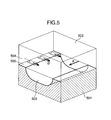
- the event pressure is sufficient for generating a surface pressure sufficient for making the first substrate 103 and the second substrate 104 contact closely each other. If the first micro chamber 307 and second micro chamber 302 have a height of about hundreds ⁇ m, a diameter of several millimeters on a diaphragm structure of a thickness of 1 mm, a deformation of the diaphragm is not negligible with respect to the height of about hundreds ⁇ m of the micro chamber.
- the second liquid is discharged from the nozzles 504 evenly into the first liquid in a micro flow path 503 formed by making the first substrate 501 and the second substrate 502 contact closely each other.
- the micro nozzles 504 of a width of several ⁇ m to tens ⁇ m need to be mounted in high density. Therefore, a width of a sealing surface between the micro nozzles 504 is made from tens ⁇ m to hundreds ⁇ m. Since a deterioration of the sealing performance on the sealing surface causes a failure of forming the parallel flow of thousands layers, the first substrate 501 and the second substrate 502 are made contact each other closely over the whole surfaces thereof to obtain securely the sealing performance.
- the third substrate 104 is arranged to be prevented from contacting the second substrate 103 so that the uniform pressing force is prevented from being applied to the deformable area. That is, the through hole 111 is formed only on the central area of the third substrate 102 contacting the area of the first micro chamber 201. The pressing on the area of the first micro chamber 201 is prevented. As a matter of course, it is preferable that non-pressing area is formed on the area of the third substrate 102 contacting the area of the second micro chamber 203.
- the third substrate 102 is made of a material having rubber elasticity or metal such as copper, aluminum or the like plastically deformable. Further, the pressing force is obtained by inserting the screw into the through holes 113 on the fourth substrate 101 to be screwed in the thread hole 106 formed on the fifth substrate 105.
- the third substrate 101 is used to absorb an unevenness in thickness and a curvature of the first substrate 103 and second substrate 104 to be made contact closely each other. Therefore, since it is made of a sheet of great deforming capacity, it is slightly smaller than the first substrate 103 and second substrate 104. It can expand in a planar direction when being compressed.
- a best material for the third substrate 102 is a resin sheet having the rubber elasticity and high chemical resistance. Incidentally, when being used as disposable element, a plastic deformability of metal is usable.
- the first substrate 103 and second substrate 104 have a portion whose dimension in thickness is smaller by single digit than a planar dimension of the micro chamber formed on the first substrate 103 and second substrate 104, the portion is prevented from being pressed so that a volume of the micro chamber is prevented from being decreased by even pressing over the third substrate 102. Further, the surfaces of the first substrate 103 and second substrate 104 to be made contact each other closely need to have a surface roughness for obtaining the sufficient sealing performance. Therefore, when the substrate material is stainless steel, the roughness is about 0.8 ⁇ m as Rmax in a width of about tens ⁇ m, although it varies in accordance with a width of the sealing surface separating the micro chambers from each other and the material of substrate.
- a width of the divided micro flow path increases along a flow proceeding direction. That is, a number of the micro nozzles 404 for injecting the second liquid increases along a flow proceeding direction in the micro flow path 401 so that a flow rate is increased by an amount of the liquid discharged from the numerous micro nozzles 404.
- a flow velocity increases along the flow proceeding direction in accordance with the increase of the amount of the liquid when the width of the micro flow path 401 is constant, but since the width of the micro flow path increases along the flow proceeding direction, a variation of the flow velocity is decreased so that a uniformity in diameter of the emulsion is improved.
- a material of each of the substrates 101-105 of the micro fluidic device 100 is a metal of high thermal conductivity when a temperature control is needed. But, a metallic corrosion is caused in accordance with kinds of the liquids as the first and second liquid. Therefore, surfaces of the substrates 101-105 is coated with a chemical resistance thin film through film forming process such as spattering, vapor deposition, CVD or the like.
- the thin coating film is formed by applying a solution including a coating agent onto the substrates and subsequently volatilizing an unrequired substance by thermal treatment.
- a solution of super-saturated glass is applied onto the metallic film, and subsequently the glass is precipitated.
- forming the thin film brings about a further merit such as improvement of sealing performance, if being made of a material of plastically deformable, such as the metallic thin film or resin thin film.
- a flattening treatment it is preferable for a flattening treatment to be performed after the coating.
- the micro fluidic device is made of stainless steel or glass substrate.
- the flow path on the metallic surface is formed by melting a metal to be removed from a part corresponding to the flow path through wet-etching or removing a die from the surface plated to form a thick film thereon after the die covers the part corresponding to the flow path.
- the flow path needs to be designed with taking a flow of etching liquid caused by a difference in temperature or concentration in the etching into consideration.
- an opening area of an etching mask is designed to make an etching rate at a required width or depth of the flow path as small as possible or nearly zero.
- a thick film resist is formed by film resist.
- it is formed by forming with a semiconductor micro-fabrication technique such as Deep-RIE, a shape of material such as monocrystal silicon or glass different from a metal in soluble characteristic.
- the micro flow path can be formed by plating over the formed thick film with utilizing a high dimensional accuracy of semiconductor. Further, since the surface of the substrate formed by the plating does not have a flatness sufficient for obtaining the secure sealing performance, it is finished by grinding to become finally a mirror surface.
- the flow path is formed on the glass substrate or the substrate surface of another material on which the flow path is formed is coated with glass.
- the monocrystal silicon is used as substrate material, the micro flow path is formed accurately on the monocrystal silicon substrate through the processing technique for semiconductor. Thereafter, the substrate is thermally treated to be oxidized so that uniform glass is formed on the substrate.
- the flow path When the flow path is directly formed on the glass substrate, with taking processing accuracy into consideration, it is dissolved by fluorochemical etching liquid in dry etching or dry etching for semiconductor.
- the wet etching on the glass substrate is similar to the wet etching for metal, and its accuracy is improved similarly.
- the flow path may be formed by removing treatment using sand blasting. in this case, a diameter of sand for sand blasting is made small to decrease a size of chipping. If the micro flow path is formed by shape decal transferring with hot embossing treatment, a cost for mass production can be decreased.
- the shape decal transferring is performed by the substrate having rubber elasticity such as polydimethilsiloxane and the thick film resist.
- the resin substrate such as polystyrene or polycarbonate
- the injection forming or hot embossing treatment is used.
Landscapes
- Chemical & Material Sciences (AREA)
- Chemical Kinetics & Catalysis (AREA)
- Physical Or Chemical Processes And Apparatus (AREA)
- Micromachines (AREA)
Applications Claiming Priority (1)
| Application Number | Priority Date | Filing Date | Title |
|---|---|---|---|
| JP2005143391A JP2006320772A (ja) | 2005-05-17 | 2005-05-17 | マイクロ流体デバイス |
Publications (3)
| Publication Number | Publication Date |
|---|---|
| EP1724006A2 true EP1724006A2 (fr) | 2006-11-22 |
| EP1724006A3 EP1724006A3 (fr) | 2008-02-27 |
| EP1724006B1 EP1724006B1 (fr) | 2010-09-22 |
Family
ID=36760451
Family Applications (1)
| Application Number | Title | Priority Date | Filing Date |
|---|---|---|---|
| EP06009652A Not-in-force EP1724006B1 (fr) | 2005-05-17 | 2006-05-10 | Dispositif microfluidique |
Country Status (4)
| Country | Link |
|---|---|
| US (1) | US7695685B2 (fr) |
| EP (1) | EP1724006B1 (fr) |
| JP (1) | JP2006320772A (fr) |
| DE (1) | DE602006017012D1 (fr) |
Cited By (1)
| Publication number | Priority date | Publication date | Assignee | Title |
|---|---|---|---|---|
| WO2021037999A3 (fr) * | 2019-08-28 | 2021-04-08 | Microcaps Ag | Dispositif et procédé pour générer des gouttelettes |
Families Citing this family (11)
| Publication number | Priority date | Publication date | Assignee | Title |
|---|---|---|---|---|
| JP2008238097A (ja) * | 2007-03-28 | 2008-10-09 | Tosoh Corp | 滴生成用微小流路集合体装置 |
| KR100880005B1 (ko) * | 2007-09-21 | 2009-01-22 | 한국기계연구원 | 카오틱 믹싱을 갖는 sar 마이크로 믹서 |
| JP4933464B2 (ja) * | 2008-02-21 | 2012-05-16 | 東レエンジニアリング株式会社 | マイクロリアクタ |
| JP5143082B2 (ja) * | 2009-05-22 | 2013-02-13 | 株式会社日立製作所 | 液液抽出システム |
| WO2012008497A1 (fr) * | 2010-07-13 | 2012-01-19 | 国立大学法人東京工業大学 | Appareil pour la production de microgouttelettes de liquide |
| US8346827B2 (en) | 2010-09-28 | 2013-01-01 | International Business Machines Corporation | Multimedia data delivery method and system |
| JP6427753B2 (ja) * | 2013-09-11 | 2018-11-28 | 国立大学法人大阪大学 | 熱対流生成用チップ、熱対流生成装置、及び熱対流生成方法 |
| CN103949170A (zh) * | 2014-05-04 | 2014-07-30 | 聊城大学 | 一种分流汇流型混合器及混合方法 |
| JP6714277B2 (ja) * | 2014-05-08 | 2020-06-24 | 国立大学法人大阪大学 | 熱対流生成用チップ |
| JP7356241B2 (ja) * | 2019-03-18 | 2023-10-04 | フコク物産株式会社 | マイクロ流体デバイス |
| CN111330656A (zh) * | 2020-03-03 | 2020-06-26 | 东南大学 | 一种微米颗粒悬液体积浓缩微流控器件 |
Citations (4)
| Publication number | Priority date | Publication date | Assignee | Title |
|---|---|---|---|---|
| US5887977A (en) | 1997-09-30 | 1999-03-30 | Uniflows Co., Ltd. | Stationary in-line mixer |
| JP2000273188A (ja) | 1999-03-24 | 2000-10-03 | Natl Food Res Inst | 単分散固体脂質マイクロスフィアの製造方法 |
| US20020140940A1 (en) | 2001-02-28 | 2002-10-03 | Bambot Shabbir B. | System and method for measurement and analysis of a sample by absorption spectrophotometry |
| WO2002089962A2 (fr) | 2001-05-07 | 2002-11-14 | INSTITUT FüR MIKROTECHNIK MAINZ GMBH | Procede et micromelangeur statique conçu pour melanger au moins deux fluides |
Family Cites Families (6)
| Publication number | Priority date | Publication date | Assignee | Title |
|---|---|---|---|---|
| DE69413012T2 (de) * | 1993-03-19 | 1999-03-25 | Du Pont | Integrierte vorrichtung für chemische verfahrensschritte und herstellungsverfahren dafür |
| DE19708472C2 (de) * | 1997-02-20 | 1999-02-18 | Atotech Deutschland Gmbh | Herstellverfahren für chemische Mikroreaktoren |
| US6572830B1 (en) * | 1998-10-09 | 2003-06-03 | Motorola, Inc. | Integrated multilayered microfludic devices and methods for making the same |
| DE10041823C2 (de) * | 2000-08-25 | 2002-12-19 | Inst Mikrotechnik Mainz Gmbh | Verfahren und statischer Mikrovermischer zum Mischen mindestens zweier Fluide |
| US7097347B2 (en) * | 2001-05-07 | 2006-08-29 | Uop Llc | Static mixer and process for mixing at least two fluids |
| JP4804718B2 (ja) * | 2003-04-28 | 2011-11-02 | 富士フイルム株式会社 | 流体混合装置、及び、流体混合システム |
-
2005
- 2005-05-17 JP JP2005143391A patent/JP2006320772A/ja active Pending
-
2006
- 2006-05-10 EP EP06009652A patent/EP1724006B1/fr not_active Not-in-force
- 2006-05-10 DE DE602006017012T patent/DE602006017012D1/de active Active
- 2006-05-15 US US11/439,821 patent/US7695685B2/en not_active Expired - Fee Related
Patent Citations (4)
| Publication number | Priority date | Publication date | Assignee | Title |
|---|---|---|---|---|
| US5887977A (en) | 1997-09-30 | 1999-03-30 | Uniflows Co., Ltd. | Stationary in-line mixer |
| JP2000273188A (ja) | 1999-03-24 | 2000-10-03 | Natl Food Res Inst | 単分散固体脂質マイクロスフィアの製造方法 |
| US20020140940A1 (en) | 2001-02-28 | 2002-10-03 | Bambot Shabbir B. | System and method for measurement and analysis of a sample by absorption spectrophotometry |
| WO2002089962A2 (fr) | 2001-05-07 | 2002-11-14 | INSTITUT FüR MIKROTECHNIK MAINZ GMBH | Procede et micromelangeur statique conçu pour melanger au moins deux fluides |
Cited By (4)
| Publication number | Priority date | Publication date | Assignee | Title |
|---|---|---|---|---|
| WO2021037999A3 (fr) * | 2019-08-28 | 2021-04-08 | Microcaps Ag | Dispositif et procédé pour générer des gouttelettes |
| IL290405B1 (en) * | 2019-08-28 | 2025-10-01 | Microcaps Ag | Device and method for forming drops |
| IL290405B2 (en) * | 2019-08-28 | 2026-02-01 | Microcaps Ag | Device and method for forming drops |
| US12564820B2 (en) | 2019-08-28 | 2026-03-03 | Microcaps Ag | Device and method for generating droplets |
Also Published As
| Publication number | Publication date |
|---|---|
| US20060275180A1 (en) | 2006-12-07 |
| DE602006017012D1 (de) | 2010-11-04 |
| EP1724006B1 (fr) | 2010-09-22 |
| US7695685B2 (en) | 2010-04-13 |
| EP1724006A3 (fr) | 2008-02-27 |
| JP2006320772A (ja) | 2006-11-30 |
Similar Documents
| Publication | Publication Date | Title |
|---|---|---|
| EP1724006B1 (fr) | Dispositif microfluidique | |
| CN105164308B (zh) | 化学气相沉积装置 | |
| CN105143507B (zh) | 化学气相沉积装置 | |
| US6730175B2 (en) | Ceramic substrate support | |
| US5595602A (en) | Diffuser for uniform gas distribution in semiconductor processing and method for using the same | |
| US20070290517A1 (en) | Non-Contact Transport Apparatus | |
| US7780929B2 (en) | Fluid mixing apparatus and fluid mixing method | |
| US20040237892A1 (en) | Micromachines for delivering precursors and gases for film deposition | |
| TWI503441B (zh) | 包含複數個擴散熔接盤之氣體分配器以及此種氣體分配器之製造方法 | |
| WO2010011852A1 (fr) | Procédé et système de fabrication de puces fluidiques intégrées | |
| JP4796129B2 (ja) | マイクロエバポレータ | |
| US20160084806A1 (en) | Micro-Machined Frit and Flow Distribution Devices for Liquid Chromatography | |
| US11536394B2 (en) | Micro fluid actuator | |
| US7758814B2 (en) | Microfluidic fluid distribution manifold for use with multi-channel reactor systems | |
| WO2004103886A2 (fr) | Canaux pour microfluides fabriques par procede microscopique | |
| JP3888275B2 (ja) | マイクロミキサー | |
| US11905168B2 (en) | Manufacturing method of miniature fluid actuator | |
| TW202246929A (zh) | 微流控晶片 | |
| US11796085B2 (en) | Non-elastomeric, non-polymeric, non-metallic membrane valves for semiconductor processing equipment | |
| JP4872320B2 (ja) | マイクロミキサー | |
| JP2008238097A (ja) | 滴生成用微小流路集合体装置 | |
| US20060118511A1 (en) | Micro-machined nozzles | |
| EP1762298B1 (fr) | Microreacteur à deux solutions ayant cannelures en forme de secteur | |
| US11583856B2 (en) | Bio-information detection substrate and gene chip | |
| JP3694878B2 (ja) | マイクロ混合器 |
Legal Events
| Date | Code | Title | Description |
|---|---|---|---|
| PUAI | Public reference made under article 153(3) epc to a published international application that has entered the european phase |
Free format text: ORIGINAL CODE: 0009012 |
|
| AK | Designated contracting states |
Kind code of ref document: A2 Designated state(s): AT BE BG CH CY CZ DE DK EE ES FI FR GB GR HU IE IS IT LI LT LU LV MC NL PL PT RO SE SI SK TR |
|
| AX | Request for extension of the european patent |
Extension state: AL BA HR MK YU |
|
| RIN1 | Information on inventor provided before grant (corrected) |
Inventor name: KOIDE, AKIRA,H Inventor name: ENDO, YOSHISHIGE Inventor name: ITO, YUZURU |
|
| PUAL | Search report despatched |
Free format text: ORIGINAL CODE: 0009013 |
|
| AK | Designated contracting states |
Kind code of ref document: A3 Designated state(s): AT BE BG CH CY CZ DE DK EE ES FI FR GB GR HU IE IS IT LI LT LU LV MC NL PL PT RO SE SI SK TR |
|
| AX | Request for extension of the european patent |
Extension state: AL BA HR MK YU |
|
| 17P | Request for examination filed |
Effective date: 20080827 |
|
| AKX | Designation fees paid |
Designated state(s): DE FR GB |
|
| 17Q | First examination report despatched |
Effective date: 20081106 |
|
| GRAP | Despatch of communication of intention to grant a patent |
Free format text: ORIGINAL CODE: EPIDOSNIGR1 |
|
| GRAS | Grant fee paid |
Free format text: ORIGINAL CODE: EPIDOSNIGR3 |
|
| GRAA | (expected) grant |
Free format text: ORIGINAL CODE: 0009210 |
|
| AK | Designated contracting states |
Kind code of ref document: B1 Designated state(s): DE FR GB |
|
| REG | Reference to a national code |
Ref country code: GB Ref legal event code: FG4D |
|
| REF | Corresponds to: |
Ref document number: 602006017012 Country of ref document: DE Date of ref document: 20101104 Kind code of ref document: P |
|
| PLBE | No opposition filed within time limit |
Free format text: ORIGINAL CODE: 0009261 |
|
| STAA | Information on the status of an ep patent application or granted ep patent |
Free format text: STATUS: NO OPPOSITION FILED WITHIN TIME LIMIT |
|
| 26N | No opposition filed |
Effective date: 20110623 |
|
| REG | Reference to a national code |
Ref country code: DE Ref legal event code: R097 Ref document number: 602006017012 Country of ref document: DE Effective date: 20110623 |
|
| PGFP | Annual fee paid to national office [announced via postgrant information from national office to epo] |
Ref country code: GB Payment date: 20120320 Year of fee payment: 7 |
|
| PGFP | Annual fee paid to national office [announced via postgrant information from national office to epo] |
Ref country code: DE Payment date: 20120531 Year of fee payment: 7 |
|
| PGFP | Annual fee paid to national office [announced via postgrant information from national office to epo] |
Ref country code: FR Payment date: 20120618 Year of fee payment: 7 |
|
| GBPC | Gb: european patent ceased through non-payment of renewal fee |
Effective date: 20130510 |
|
| PG25 | Lapsed in a contracting state [announced via postgrant information from national office to epo] |
Ref country code: DE Free format text: LAPSE BECAUSE OF NON-PAYMENT OF DUE FEES Effective date: 20131203 |
|
| REG | Reference to a national code |
Ref country code: DE Ref legal event code: R119 Ref document number: 602006017012 Country of ref document: DE Effective date: 20131203 |
|
| REG | Reference to a national code |
Ref country code: FR Ref legal event code: ST Effective date: 20140131 |
|
| PG25 | Lapsed in a contracting state [announced via postgrant information from national office to epo] |
Ref country code: GB Free format text: LAPSE BECAUSE OF NON-PAYMENT OF DUE FEES Effective date: 20130510 |
|
| PG25 | Lapsed in a contracting state [announced via postgrant information from national office to epo] |
Ref country code: FR Free format text: LAPSE BECAUSE OF NON-PAYMENT OF DUE FEES Effective date: 20130531 |