EP1724123A2 - Roue pour véhicules - Google Patents
Roue pour véhicules Download PDFInfo
- Publication number
- EP1724123A2 EP1724123A2 EP06120464A EP06120464A EP1724123A2 EP 1724123 A2 EP1724123 A2 EP 1724123A2 EP 06120464 A EP06120464 A EP 06120464A EP 06120464 A EP06120464 A EP 06120464A EP 1724123 A2 EP1724123 A2 EP 1724123A2
- Authority
- EP
- European Patent Office
- Prior art keywords
- duct
- wheel
- vehicle wheel
- spoke
- rim
- Prior art date
- Legal status (The legal status is an assumption and is not a legal conclusion. Google has not performed a legal analysis and makes no representation as to the accuracy of the status listed.)
- Withdrawn
Links
- 238000004891 communication Methods 0.000 claims abstract description 11
- 239000007787 solid Substances 0.000 claims description 18
- 238000007789 sealing Methods 0.000 claims description 7
- 238000004519 manufacturing process Methods 0.000 claims description 5
- 238000005553 drilling Methods 0.000 claims description 4
- 238000000034 method Methods 0.000 claims description 4
- 238000005266 casting Methods 0.000 claims description 2
- 229910000838 Al alloy Inorganic materials 0.000 claims 2
- 229910001369 Brass Inorganic materials 0.000 claims 1
- 229910000861 Mg alloy Inorganic materials 0.000 claims 1
- 239000010951 brass Substances 0.000 claims 1
- 239000012530 fluid Substances 0.000 description 3
- 230000008901 benefit Effects 0.000 description 2
- 229910001234 light alloy Inorganic materials 0.000 description 2
- 238000003754 machining Methods 0.000 description 2
- 239000000463 material Substances 0.000 description 2
- 238000010079 rubber tapping Methods 0.000 description 2
- 239000011324 bead Substances 0.000 description 1
- 230000005540 biological transmission Effects 0.000 description 1
- 238000005260 corrosion Methods 0.000 description 1
- 230000007797 corrosion Effects 0.000 description 1
- 230000008878 coupling Effects 0.000 description 1
- 238000010168 coupling process Methods 0.000 description 1
- 238000005859 coupling reaction Methods 0.000 description 1
- 230000007423 decrease Effects 0.000 description 1
- 230000000694 effects Effects 0.000 description 1
- 238000003780 insertion Methods 0.000 description 1
- 230000037431 insertion Effects 0.000 description 1
- 238000012986 modification Methods 0.000 description 1
- 230000004048 modification Effects 0.000 description 1
- 230000008569 process Effects 0.000 description 1
- 238000005096 rolling process Methods 0.000 description 1
- 230000008719 thickening Effects 0.000 description 1
Images



Classifications
-
- B—PERFORMING OPERATIONS; TRANSPORTING
- B60—VEHICLES IN GENERAL
- B60B—VEHICLE WHEELS; CASTORS; AXLES FOR WHEELS OR CASTORS; INCREASING WHEEL ADHESION
- B60B1/00—Spoked wheels; Spokes thereof
- B60B1/06—Wheels with compression spokes
- B60B1/08—Wheels with compression spokes formed by casting
Definitions
- the present invention relates to a wheel for vehicles; in particular, the present invention relates to wheels suitable for use on motorcycles.
- each brake-disc and brake-caliper assembly constitute an obstacle which hinders access to the tyre-inflation valve which projects radially from the rim towards the hub of the wheel.
- the transmission unit comprising a chain wheel coaxial with the wheel and a chain associated therewith, together with a casing system and, on the other side, there is the brake disc; moreover, on both sides, there are the side members of the fork which supports the rear wheel.
- a wheel comprising two annular ducts, one in the region of the wheel hub and the other in the region of the periphery of the wheel, the annular ducts being in fluid communication with one another by means of at least one internally hollow spoke.
- the object of the present invention is to provide a wheel for vehicles which solves the problems mentioned with reference to the prior art.
- Figure 1 is a side view of a wheel according to the invention
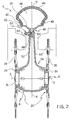
- Figure 2 is a section through the wheel of Figure 1, taken on the line II-II of Figure 1,
- Figure 3 shows a detail of Figure 2 on an enlarged scale
- Figure 4 is a perspective view of a portion of the wheel of Figure 1,
- Figure 4A shows a detail of Figure 4 on an enlarged scale
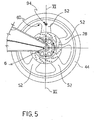
- Figure 5 is a side view of a further embodiment of the wheel according to the invention.
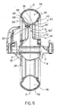
- Figure 6 is a section through the wheel of Figure 5, taken on the line VI-VI of Figure 5.
- radial direction is intended to define herein a direction substantially perpendicular to the axis of rotation of the wheel.
- axial direction is intended to define herein a direction substantially parallel to the axis of rotation of the wheel.
- tangential direction is intended to define herein a direction substantially perpendicular to the axial direction and to the radial direction.
- a vehicle wheel unit is generally indicated 4.
- the wheel 4 has a central plane R which substantially divides the wheel 4 into two half-portions; in a configuration in which the wheel 4 is mounted on a respective axle 6 that defines an axis of rotation X of the wheel 4, these two half-portions are arranged symmetrically on opposite sides of the central plane R.
- the central plane R is arranged perpendicularly relative to the axis of rotation X and to the axle 6 and divides the wheel 4 into two half-portions having substantially the same axial dimensions.
- the wheel 4 comprises a hub 8 suitable for being mounted rotatably on the axle 6 of the wheel 4.
- the hub 8 has a substantially barrel-like configuration with a hollow cross-section and is arranged symmetrically on opposite sides of the central plane R.
- the hub 8 comprises a hole 16 which is arranged axially and is suitable for housing support means, for example, rolling bearings, for the axle 6 of the wheel 4.
- the hub 8 comprises annular seats 24 suitable for constituting bearing, locating and fixing surfaces for brake discs 28 mounted coaxially relative to the hub 8 and parallel to the central plane R of the wheel.
- the wheel 4 further comprises an annular rim 32 coaxial with the hub 8 and arranged symmetrically relative to the central plane R of the wheel.
- the rim 32 comprises a channel 36 having, on axially opposite sides, two rim flanges 40 which extend substantially radially around the entire circumference of the channel 36.
- the rim 32 is suitable for being associated with a tyre 44, by the hermetic coupling of beads of the tyre with the rim flanges 40.
- the rim 32 comprises a lateral surface 46 which, together with the tyre 44, delimits an inflation chamber 48 suitable for hermetically containing a gas under pressure so as to support the tyre.
- inflation chamber is intended to define herein a substantially toroidal chamber suitable for containing a gas under pressure. This definition refers both to tubeless tyres in which the inflation chamber is formed directly by the internal surface of the tyre and by the rim, hermetically coupled with one another, and to conventional tyres in which the inflation chamber is constituted by an inner tube interposed in the space between the tyre and the rim.
- the wheel 4 comprises at least one spoke 52 which fixes the rim 32 and the hub 8 together for rotation relative to the axle 6 of the wheel 4.
- the spoke 52 extends substantially radially between the rim 32 and the hub 8, preferably so as to be arranged symmetrically with respect to the central plane R.
- the spoke 52 is a predominantly hollow element having thin walls which are connected to the hub 8 and to the rim 32.
- the spoke 52 has a trapezoidal overall shape with a width which decreases from the hub 8 towards the rim 32.
- the spoke 52 comprises, at radially opposite ends, a hub-attachment portion 56 and a rim-attachment portion 60.
- the hub-attachment portion 56 comprises a connecting portion between the hub 8 and the spoke 52.
- the rim-attachment portion 60 comprises at least one portion which constitutes a solid body 64; in other words, the spoke has a solid cross-section in the region of the solid body 64.
- the solid body 64 is preferably positioned at the greatest possible radial distance from the hub.
- the solid body 64 constitutes a portion with a solid cross-section, that is a portion through which no gas-flow is permitted.
- the solid body separates the spoke into two portions 64' and 64" which are disposed on radially opposite sides of the solid body and are not in flow communication with one another.
- a first duct 68 is formed in the region of the solid body 64 and extends substantially along the spoke 52, for example, radially; the first duct 68 faces the lateral surface 46 of the rim 32 and the inflation chamber 48 so as to be in flow communication with the inflation chamber 48.
- the first duct 68 extends partially through the solid body 64, that is, it does not constitute a through-hole extending through the solid body 64, and does not therefore put the portions 64' and 64" of the spoke into flow communication.
- the first duct 68 is blind in the direction in which the spoke 52 extends, for example, in a radial direction towards the hub 8.
- the solid body 64 further comprises a second duct 72 which, in one embodiment, is arranged substantially perpendicularly relative to the first duct 68 and to the central plane R.
- the second duct 72 comprises a first end 76 facing towards the first duct 68 and in flow communication therewith, and a second end 80, remote from the first end 76 and having an opening 84 with which the second duct 72 emerges laterally from the spoke 52.
- the opening 84 is suitable for being connected to inflation means such as, for example, a tyre-inflation gauge nozzle.
- the second duct 72 also extends partially through the solid body 64; that is, it does not constitute a through-hole extending through the solid body 64, but extends within the solid body as far as its intersection with the first duct 68.
- the first and second ducts 68, 72 are thus in flow communication with one another and with the inflation chamber 48.
- the first and second ducts constitute a path for the flow of gas from an external gas supply to the inflation chamber of the tyre.
- the first and second ducts 68, 72 advantageously extend for a distance less than an axial thickness or dimension of the rim-attachment portion 60 of the spoke 52.
- the second duct 72 emerges, in the region of the second end 80, in a raised portion 88 which projects from the spoke 52, for example, in an axial direction, away from the central plane R.
- the raised portion 88 constitutes an axial thickening of the rim-attachment portion 60.
- the raised portion 88 comprises a flattened surface 92 arranged substantially parallel to the central plane R and substantially perpendicular to the axle 6.
- the second duct 72 is advantageously positioned outside an axial projection of at least one brake disc that can be associated firmly and coaxially with the hub 8 at an axial end 20 of the hub 8.
- the second duct 72 is positioned outside a circle having its centre on the rotation axis and touching the outer edge of the brake disc.
- the distance between the second duct and the rotation axis X is greater than the radius of the brake disc that can be associated with the wheel.
- the second duct 72 advantageously constitutes a seat for housing an inflation valve 94.
- the second duct 72 has a threaded portion 100 in an internal side wall 96 thereof.
- the second duct 72 has a chamfer 104 for facilitating the insertion of threaded bodies into the second duct 72.
- the inflation valve 94 which can be used to regulate the flow of a fluid through the first and second ducts 68, 72 and from these to the inflation chamber 48, is suitable for being housed at least partially in the second duct 72.
- the inflation valve 94 comprises a substantially cylindrical valve body 108 having a connection portion 112 which has, on an external side wall, a threaded portion 116 suitable for screwing into the threaded portion 100 of the internal side wall 96 of the second duct 72.
- the valve body 108 comprises a collar 120 suitable for forming a stop element or abutment during the mounting of the valve 94 in the second duct 72, by coming into abutment with the flattened surface 92.
- the collar 120 is formed with a polygonal, preferably hexagonal, shape similar to a nut or screw head so that the valve can be gripped and screwed into its seat by a tool such as, for example, a socket spanner.
- the collar 120 comprises an annular groove 124 suitable for housing sealing means 128, for example, an 0-ring-type sealing ring.
- the sealing means 128 is suitable for forming a fluid-tight seal between the inflation valve 94 and the second duct 72.
- the threaded portion 116 preferably extends for a distance less than the depth of the second duct 72; in other words, the valve portion included between an end of the valve to be inserted in the seat and the collar 120 is shorter than the length of the second duct 72.
- the sealing means 128 such as, for example, an 0-ring housed in the annular groove 124, can therefore be suitably preloaded.
- the second duct houses a substantially cylindrical bush having a first thread on an external side wall and a second thread on its internal side wall.
- the bush can be screwed into the threaded portion 100 of the second duct 72 so as to be inserted in the duct.
- the threaded portion 100 preferably comprises a thread suitable for forming a self-tapping connection with the bush.
- the thread on the internal side wall of the bush is suitable for engaging a corresponding thread of a valve body 108 as described above.
- the wheel described can, for example, be produced by a casting process in which the die is suitable for producing a spoke having, in a solid portion, a first duct which is arranged substantially radially and is produced, for example, by means of a pin or core which extends radially as far as the channel of the rim so that the first duct is in flow communication with the channel and hence with the inflation chamber of the tyre that can be associated with the wheel.
- the die also comprises at least one further core suitable for forming the axial through-hole that extends through the hub and can house the wheel axle.
- the die also enables a raised portion to be produced, projecting axially from at least one spoke.
- the raised portion stiffens the rim-attachment portion of the spoke, by virtue of the increase in its resisting cross-section and also enables a threaded portion long enough to ensure secure screwing and tightening of a valve to be formed inside the second duct.
- the axial drilling operations are performed.
- a precision drilling of the hub is performed so as to ensure adequate perpendicularity between the central plane of the rim and the hole in the hub as well as correct keying of support bearings between the hub and the axle;
- the second duct is also produced by means of a drilling operation performed in a substantially axial direction perpendicular to the raised portion of the spoke, so as to intersect the first duct.
- both the axial ends of the hub and the raised portion are then flattened, the flattened surface of the raised portion being suitable for constituting a stop abutment for an inflation valve fixed in the second duct.
- the second axial duct produced thus has an outer end comprising a flattened surface suitable for receiving an inflation valve in abutment and an inner end which is in flow communication with the first duct and, through the first duct, with the inflation chamber.
- the valve By virtue of the perpendicularity between the flattened surface and the axle, after the inflation valve has been mounted on the wheel, the valve is positioned axially and perpendicularly relative to the flattened surface; dynamic imbalances of the wheel are thus limited and the fitting of the air-supply hose on the valve is facilitated.
- the flattened surface of the raised portion also constitutes a bearing surface for sealing means such as, for example, an 0-ring to be interposed between the inflation valve and the second duct.
- sealing means such as, for example, an 0-ring to be interposed between the inflation valve and the second duct.
- the flatness of the flattened surface is useful for ensuring correct deformation of the ring as a result of the screwing of the valve into its seat and hence a resulting hermetic seal thereof between the surfaces of the valve and of the spoke, between which it is inserted.
- the wheel described overcomes the problems affecting wheels of the prior art.
- the wheel described is especially advantageous when mounted on motorcycles.
- the wheel described can advantageously also be produced with spokes of complex and curved geometrical shapes.
- the hose of the nozzle does not have to be bent it is possible to perform the inflation with one hand alone, without leakages of air taking place between the nozzle and the valve stem.
- the machining of the valve seat takes place in a direction substantially parallel to the wheel axle as well as to the holes for the fixing of the hub to the axle. All of the parallel holes can thus be machined without the need to perform a suitable re-gripping step for the machining of the valve seat.
- the volume of air contained in the first and second ducts is extremely small. Variations in pressure inside the inflation chamber of the tyre in dependence on temperature are thus limited since the amount of gas outside the inflation chamber is extremely small.
- the wheel described can be made of light or ultra-light alloy of any type so as to limit mass and gyroscopic effects.
- the bush interposed between the valve and the second duct prevents corrosion of the valve seat by preventing direct contact between the material of the rim and the material of the valve.
- ductile light alloys which are unsuitable for being machined in order to produce the fine-pitch threads that are typical of inflation valves, it is possible to interpose a bush having a long-pitch thread, for example, of the self-tapping type at the interface between the seat and the bush, and a fine-pitch thread at the interface between the bush and the valve.
- the inflation valve can easily be fitted from the exterior since it can be screwed directly into its seat, avoiding the need to insert the valve through a wall of the rim and then fix it with a nut from the opposite and inner side of the rim.
- spokes having curved shapes that is, spokes which do not extend linearly along a radius of the rim.
- spokes that are arranged in non-symmetrical positions with respect to the central plane R it is possible to produce spokes having curved shapes, that is, spokes which do not extend linearly along a radius of the rim.
Landscapes
- Engineering & Computer Science (AREA)
- Mechanical Engineering (AREA)
- Tires In General (AREA)
- Regulating Braking Force (AREA)
Priority Applications (1)
| Application Number | Priority Date | Filing Date | Title |
|---|---|---|---|
| EP06120464A EP1724123A3 (fr) | 2003-04-18 | 2003-04-18 | Roue pour véhicules |
Applications Claiming Priority (2)
| Application Number | Priority Date | Filing Date | Title |
|---|---|---|---|
| EP06120464A EP1724123A3 (fr) | 2003-04-18 | 2003-04-18 | Roue pour véhicules |
| EP03723073A EP1615780B1 (fr) | 2003-04-18 | 2003-04-18 | Roue pour vehicules |
Related Parent Applications (1)
| Application Number | Title | Priority Date | Filing Date |
|---|---|---|---|
| EP03723073A Division EP1615780B1 (fr) | 2003-04-18 | 2003-04-18 | Roue pour vehicules |
Publications (2)
| Publication Number | Publication Date |
|---|---|
| EP1724123A2 true EP1724123A2 (fr) | 2006-11-22 |
| EP1724123A3 EP1724123A3 (fr) | 2007-01-03 |
Family
ID=37102288
Family Applications (1)
| Application Number | Title | Priority Date | Filing Date |
|---|---|---|---|
| EP06120464A Withdrawn EP1724123A3 (fr) | 2003-04-18 | 2003-04-18 | Roue pour véhicules |
Country Status (2)
| Country | Link |
|---|---|
| EP (1) | EP1724123A3 (fr) |
| AT (1) | ATE340085T1 (fr) |
Family Cites Families (4)
| Publication number | Priority date | Publication date | Assignee | Title |
|---|---|---|---|---|
| JPS5339922Y2 (fr) * | 1975-10-04 | 1978-09-27 | ||
| JPS5536113A (en) * | 1978-08-31 | 1980-03-13 | Suzuki Motor Co Ltd | Tyre inner pressure drop alarm |
| JPS62112601U (fr) * | 1986-01-06 | 1987-07-17 | ||
| DE8905057U1 (de) * | 1989-04-21 | 1989-07-20 | Dal Cero, Alberto, Piossasco, Turin/Torino | Rad mit schlauchlosem Reifen für ein Kraftfahrzeug |
-
2003
- 2003-04-18 AT AT03723073T patent/ATE340085T1/de not_active IP Right Cessation
- 2003-04-18 EP EP06120464A patent/EP1724123A3/fr not_active Withdrawn
Non-Patent Citations (1)
| Title |
|---|
| None |
Also Published As
| Publication number | Publication date |
|---|---|
| EP1724123A3 (fr) | 2007-01-03 |
| ATE340085T1 (de) | 2006-10-15 |
Similar Documents
| Publication | Publication Date | Title |
|---|---|---|
| US7137671B2 (en) | Attachment system for the spokes of a bicycle wheel | |
| US7066556B2 (en) | Bicycle hub | |
| CN102271931B (zh) | 用于车辆尤其是摩托车的无内胎的辐条轮 | |
| US20040222690A1 (en) | Bicycle rim | |
| EP1375195B1 (fr) | Jante de roue de véhicule | |
| KR20000070120A (ko) | 안전 분해 차륜 조립체 | |
| EP1615780B1 (fr) | Roue pour vehicules | |
| US6994189B2 (en) | Brakable wheel hub device | |
| EP1431069A2 (fr) | Jante de bicyclette | |
| CA2547536A1 (fr) | Roue a rayons pour pneus | |
| EP2612765A2 (fr) | Ensemble de jante | |
| TWI606938B (zh) | 用於至少部分體力操作的車輛且特別是自行車之輪子 | |
| TW202218901A (zh) | 自行車輻輪與相關的輪的輻條附接組件及製造此種輪的程序 | |
| US4718639A (en) | Tire valve bodies | |
| EP1629996B1 (fr) | Roue à rayons pour bicyclettes, ses composants et procédé de fabrication | |
| US20050023883A1 (en) | Bicycle rim | |
| EP1724123A2 (fr) | Roue pour véhicules | |
| JP4610532B2 (ja) | 自転車用ディスクブレーキハブ | |
| JP2010285050A (ja) | ランフラット用中子およびその装着方法 | |
| US4019782A (en) | Automotive wire wheel and manufacturing method | |
| EP2052875A1 (fr) | Roue à rayons | |
| CN113997726B (zh) | 旨在制造辐条自行车轮的过程和相关轮 | |
| JP2008239025A (ja) | 車輪用転がり軸受装置 | |
| JP3237721B2 (ja) | スポークホイール | |
| TWI918091B (zh) | 氣嘴閥桿組件 |
Legal Events
| Date | Code | Title | Description |
|---|---|---|---|
| PUAI | Public reference made under article 153(3) epc to a published international application that has entered the european phase |
Free format text: ORIGINAL CODE: 0009012 |
|
| AC | Divisional application: reference to earlier application |
Ref document number: 1615780 Country of ref document: EP Kind code of ref document: P |
|
| AK | Designated contracting states |
Kind code of ref document: A2 Designated state(s): AT BE BG CH CY CZ DE DK EE ES FI FR GB GR HU IE IT LI LU MC NL PT RO SE SI SK TR |
|
| PUAL | Search report despatched |
Free format text: ORIGINAL CODE: 0009013 |
|
| AK | Designated contracting states |
Kind code of ref document: A3 Designated state(s): AT BE BG CH CY CZ DE DK EE ES FI FR GB GR HU IE IT LI LU MC NL PT RO SE SI SK TR |
|
| RIC1 | Information provided on ipc code assigned before grant |
Ipc: B60B 1/08 20060101AFI20061013BHEP |
|
| AKX | Designation fees paid | ||
| REG | Reference to a national code |
Ref country code: DE Ref legal event code: 8566 |
|
| STAA | Information on the status of an ep patent application or granted ep patent |
Free format text: STATUS: THE APPLICATION IS DEEMED TO BE WITHDRAWN |
|
| 18D | Application deemed to be withdrawn |
Effective date: 20070704 |