EP1724144B1 - Ein Verfahren zum Schweißen des Einfüllstutzens des Treibstoffbehälters eines Kraftfahrzeuges - Google Patents
Ein Verfahren zum Schweißen des Einfüllstutzens des Treibstoffbehälters eines Kraftfahrzeuges Download PDFInfo
- Publication number
- EP1724144B1 EP1724144B1 EP05425351A EP05425351A EP1724144B1 EP 1724144 B1 EP1724144 B1 EP 1724144B1 EP 05425351 A EP05425351 A EP 05425351A EP 05425351 A EP05425351 A EP 05425351A EP 1724144 B1 EP1724144 B1 EP 1724144B1
- Authority
- EP
- European Patent Office
- Prior art keywords
- welding
- axis
- focusing head
- breather pipe
- along
- Prior art date
- Legal status (The legal status is an assumption and is not a legal conclusion. Google has not performed a legal analysis and makes no representation as to the accuracy of the status listed.)
- Expired - Lifetime
Links
- 238000003466 welding Methods 0.000 title claims description 53
- 239000000945 filler Substances 0.000 title claims description 28
- 238000000034 method Methods 0.000 title claims description 17
- 239000002828 fuel tank Substances 0.000 title claims description 6
- 230000033001 locomotion Effects 0.000 claims description 16
- 229910000831 Steel Inorganic materials 0.000 claims description 2
- 239000010959 steel Substances 0.000 claims description 2
- 238000007689 inspection Methods 0.000 claims 1
- 210000003739 neck Anatomy 0.000 description 21
- 239000000446 fuel Substances 0.000 description 4
- 239000000463 material Substances 0.000 description 4
- 229910001220 stainless steel Inorganic materials 0.000 description 4
- 239000010935 stainless steel Substances 0.000 description 4
- 239000002184 metal Substances 0.000 description 3
- 230000016571 aggressive behavior Effects 0.000 description 2
- 230000005540 biological transmission Effects 0.000 description 2
- 238000010586 diagram Methods 0.000 description 2
- 238000010191 image analysis Methods 0.000 description 2
- 238000004519 manufacturing process Methods 0.000 description 2
- 230000003287 optical effect Effects 0.000 description 2
- 239000000126 substance Substances 0.000 description 2
- 238000004458 analytical method Methods 0.000 description 1
- 230000000903 blocking effect Effects 0.000 description 1
- 238000005219 brazing Methods 0.000 description 1
- 238000001514 detection method Methods 0.000 description 1
- 238000006073 displacement reaction Methods 0.000 description 1
- 238000005516 engineering process Methods 0.000 description 1
- 238000000465 moulding Methods 0.000 description 1
- 230000035515 penetration Effects 0.000 description 1
- 238000011084 recovery Methods 0.000 description 1
- 230000001052 transient effect Effects 0.000 description 1
Images


Classifications
-
- B—PERFORMING OPERATIONS; TRANSPORTING
- B23—MACHINE TOOLS; METAL-WORKING NOT OTHERWISE PROVIDED FOR
- B23K—SOLDERING OR UNSOLDERING; WELDING; CLADDING OR PLATING BY SOLDERING OR WELDING; CUTTING BY APPLYING HEAT LOCALLY, e.g. FLAME CUTTING; WORKING BY LASER BEAM
- B23K26/00—Working by laser beam, e.g. welding, cutting or boring
- B23K26/08—Devices involving relative movement between laser beam and workpiece
- B23K26/10—Devices involving relative movement between laser beam and workpiece using a fixed support, i.e. involving moving the laser beam
- B23K26/103—Devices involving relative movement between laser beam and workpiece using a fixed support, i.e. involving moving the laser beam the laser beam rotating around the fixed workpiece
-
- B—PERFORMING OPERATIONS; TRANSPORTING
- B23—MACHINE TOOLS; METAL-WORKING NOT OTHERWISE PROVIDED FOR
- B23K—SOLDERING OR UNSOLDERING; WELDING; CLADDING OR PLATING BY SOLDERING OR WELDING; CUTTING BY APPLYING HEAT LOCALLY, e.g. FLAME CUTTING; WORKING BY LASER BEAM
- B23K26/00—Working by laser beam, e.g. welding, cutting or boring
- B23K26/08—Devices involving relative movement between laser beam and workpiece
- B23K26/0823—Devices involving rotation of the workpiece
-
- B—PERFORMING OPERATIONS; TRANSPORTING
- B23—MACHINE TOOLS; METAL-WORKING NOT OTHERWISE PROVIDED FOR
- B23K—SOLDERING OR UNSOLDERING; WELDING; CLADDING OR PLATING BY SOLDERING OR WELDING; CUTTING BY APPLYING HEAT LOCALLY, e.g. FLAME CUTTING; WORKING BY LASER BEAM
- B23K26/00—Working by laser beam, e.g. welding, cutting or boring
- B23K26/20—Bonding
- B23K26/21—Bonding by welding
- B23K26/24—Seam welding
- B23K26/28—Seam welding of curved planar seams
-
- B—PERFORMING OPERATIONS; TRANSPORTING
- B23—MACHINE TOOLS; METAL-WORKING NOT OTHERWISE PROVIDED FOR
- B23K—SOLDERING OR UNSOLDERING; WELDING; CLADDING OR PLATING BY SOLDERING OR WELDING; CUTTING BY APPLYING HEAT LOCALLY, e.g. FLAME CUTTING; WORKING BY LASER BEAM
- B23K2101/00—Articles made by soldering, welding or cutting
- B23K2101/04—Tubular or hollow articles
- B23K2101/06—Tubes
-
- B—PERFORMING OPERATIONS; TRANSPORTING
- B60—VEHICLES IN GENERAL
- B60K—ARRANGEMENT OR MOUNTING OF PROPULSION UNITS OR OF TRANSMISSIONS IN VEHICLES; ARRANGEMENT OR MOUNTING OF PLURAL DIVERSE PRIME-MOVERS IN VEHICLES; AUXILIARY DRIVES FOR VEHICLES; INSTRUMENTATION OR DASHBOARDS FOR VEHICLES; ARRANGEMENTS IN CONNECTION WITH COOLING, AIR INTAKE, GAS EXHAUST OR FUEL SUPPLY OF PROPULSION UNITS IN VEHICLES
- B60K15/00—Arrangement in connection with fuel supply of combustion engines or other fuel consuming energy converters, e.g. fuel cells; Mounting or construction of fuel tanks
- B60K15/03—Fuel tanks
- B60K15/035—Fuel tanks characterised by venting means
-
- B—PERFORMING OPERATIONS; TRANSPORTING
- B60—VEHICLES IN GENERAL
- B60K—ARRANGEMENT OR MOUNTING OF PROPULSION UNITS OR OF TRANSMISSIONS IN VEHICLES; ARRANGEMENT OR MOUNTING OF PLURAL DIVERSE PRIME-MOVERS IN VEHICLES; AUXILIARY DRIVES FOR VEHICLES; INSTRUMENTATION OR DASHBOARDS FOR VEHICLES; ARRANGEMENTS IN CONNECTION WITH COOLING, AIR INTAKE, GAS EXHAUST OR FUEL SUPPLY OF PROPULSION UNITS IN VEHICLES
- B60K15/00—Arrangement in connection with fuel supply of combustion engines or other fuel consuming energy converters, e.g. fuel cells; Mounting or construction of fuel tanks
- B60K15/03—Fuel tanks
- B60K15/04—Tank inlets
-
- B—PERFORMING OPERATIONS; TRANSPORTING
- B60—VEHICLES IN GENERAL
- B60K—ARRANGEMENT OR MOUNTING OF PROPULSION UNITS OR OF TRANSMISSIONS IN VEHICLES; ARRANGEMENT OR MOUNTING OF PLURAL DIVERSE PRIME-MOVERS IN VEHICLES; AUXILIARY DRIVES FOR VEHICLES; INSTRUMENTATION OR DASHBOARDS FOR VEHICLES; ARRANGEMENTS IN CONNECTION WITH COOLING, AIR INTAKE, GAS EXHAUST OR FUEL SUPPLY OF PROPULSION UNITS IN VEHICLES
- B60K15/00—Arrangement in connection with fuel supply of combustion engines or other fuel consuming energy converters, e.g. fuel cells; Mounting or construction of fuel tanks
- B60K15/03—Fuel tanks
- B60K15/035—Fuel tanks characterised by venting means
- B60K2015/03523—Arrangements of the venting tube
- B60K2015/03528—Mounting of venting tubes
Definitions
- the present invention relates to a method for welding the filler neck of the fuel tank of a motor vehicle as disclosed in the preamble of claim 1.
- the invention relates to welding of a breather pipe to a main pipe of the filler neck.
- US 2002/0100160 A discloses such a method.
- plastic materials have become available that are able to meet up to the technical requirements necessary for this application (resistance to chemical aggression of fuels, mechanical resistance, etc.).
- the technologies of moulding of plastic materials moreover enable complex geometries to be obtained easily and various components to be welded conveniently together.
- a filler neck for the fuel tank of a motor vehicle typically comprises a main pipe provided with an inlet filler designed to receive the delivery gun of a refuelling system and designed to be tightly connected to the tank, and a breather pipe for the fuel vapours connected so that it branches off from the main pipe, for example, from the filler or downstream thereof.
- the breather pipe is designed to be connected, in use, to a breather port of a device for recovery of the vapours associated to the tank.
- the aim of the present invention is to define a method for welding a breather pipe to the main pipe of a filler neck for the tank of a motor vehicle which will be free from the drawbacks connected to known methods.
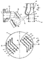
- the filler neck 2 typically comprises a main pipe 3 of axis A, provided with an inlet filler 4 designed to house a delivery gun of a refuelling system (not illustrated), and a breather pipe 5 for the fuel vapours connected so that it branches off from the main pipe 3.
- the latter is provided, for this purpose, with a seat 6 made in the filler ( Figure 4 ) or downstream thereof ( Figure 5 ), in which an end 7 of the breather pipe 5 engages, as is clearly visible in the enlarged detail of Figure 5 .
- the seat 6 can be a simple hole, as is illustrated in Figure 4 , but is preferably defined by an annular collar in relief, as clearly illustrated in the enlarged detail of Figure 5 .
- This solution presents the advantages of guiding better the end 7 of the breather pipe 5, of offering a greater surface of interface between the breather pipe 5 and the seat 6, and of enabling the execution of a weld along a plane line.
- the breather pipe 5 is generally bent, in the proximity of the end 7, in such a way as to extend in a direction substantially parallel to the main pipe 3.
- the components of the filler neck 2 are conveniently made of stainless steel.
- the equipment 1 basically comprises: a horizontal base 8; a rotary table 9, which is supported on the base 8 in such a way that it can rotate about a vertical axis B and is provided with equipment 10 for supporting and clamping a plurality of filler necks 2 to be welded; a laser generator 12; a focusing head 13; and a movement unit 14 designed to displace the focusing head 13 with respect to the rotary table 9 according to a plurality of co-ordinated axes, as will be described more fully in what follows.
- the equipment 1 further comprises a frame 15 fixed on the base 8, which supports the laser generator 12 and the movement unit 14.
- the frame 15 comprises a multiplicity of vertical uprights 16 arranged at the sharp edges of the base 8 and a meshlike superstructure 17 supported by the uprights 16, on which the generator 12 is mounted.
- the rotary table 9 is set in such a way as to project with a portion thereof on the outside of the frame 15, beyond a vertical plane defined by two adjacent uprights 16, in such a way as to define a loading station 19 for the filler necks 2 to be welded ( Figure 1 ).
- the superstructure 17 comprises a pair of guides 18 parallel to one another and to a first horizontal axis X.
- the movement unit 14 comprises a bridge 21, which is guided at the ends on the guides 18 and is mobile in the direction X, a carriage 25, which is mobile along the bridge 21 in a horizontal direction Y perpendicular to the direction X, and a vertical column 26 supported by the carriage 25 in such a way that it is mobile in a vertical direction Z.
- the focusing head 13 is fixed to a bottom end 27 of the column 26 via an articulated joint 28 that enables rotation of the focusing head 13 about an axis C parallel to the axis Z.
- the movements of the bridge 21, of the carriage 25 and of the column 26, as well as the rotation of the focusing head 13, are governed by a control unit 30, through respective electric motors and transmission units of a conventional type (not illustrated).
- the focusing head 13 is consequently mobile, with the four degrees of freedom described above, in a working space defining a welding station 29, set diametrally opposite to the loading station 19 with respect to the axis B of the rotary table 9 ( Figure 1 ).
- the laser generator 12 is conveniently of the CO 2 type, and is connected to the focusing head 13 by means of an optical reflecting system, which is of a known type and is not described in detail herein ; alternatively, a generator of an Nd:YAG type can be used, in which case the beam can be transported from the generator 12 to the focusing head 13 via optical fibres.
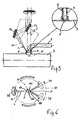
- the focusing head 13 which comprises a casing 31 defining a channel 32 for inlet of the laser beam having axis C, a plane reflecting mirror 33 designed to reflect the beam along an axis D, and a parabolic focusing mirror 34 set laterally with respect to the reflecting mirror 33, along the axis D, to focus the beam L in the focus F thereof set at the intersection between the axis M of the mirror 34 and the axis C.
- the focusing head 13 is consequently of the so-called "zero-offset" type.
- the angle between the axis M and the axis C is chosen according to the application and can be equal for example to 40°.
- the focus is not constituted by a point in the geometrical sense, but by a focal spot having non-negligible transverse and axial dimensions.
- a video camera 35 Conveniently fixed to the focusing head 13 is a video camera 35.
- the video camera 35 is connected to the control unit 30 of the movement unit of the equipment 1 and, via a software for image analysis, enables detection of the position in space of the circumferential sharp edge formed between the end section of the seat 6 and the breather pipe 5, and hence determination of the correct position of the welding line, understood as the locus of the points which identify the positions assumed by the focus F of the focusing head 13 during welding.
- the equipment 10 for supporting and clamping the filler necks 2 to be welded are of a conventional type, for example pneumatically actuated clamps, and is not described in detail herein.
- the equipment 10 is designed to support two sets 36, 37 of filler necks 2 on the rotary table 9, arranged symmetrically with respect to the axis B, so that when one set 36 is in the loading station 19 the other set 37 is in the welding station 29.
- Each set is constituted by a number of filler necks 2 defined so as to optimize the loading/unloading time, for example four.
- the filler necks 2 of each set 36, 37 are conveniently arranged alongside one another, with the breather pipes 5 arranged above the corresponding main ducts 3 and the respective welding areas appropriately spaced apart from one another in the direction of the axes X and/or Y so as to enable access of the focusing head 13.
- the breather pipes 5 are interference pre-mounted in the corresponding seats 6.
- the filler necks 2, in this condition of pre-assembly, are then loaded onto the rotary table 9 in the loading/unloading station 19, where, via the equipment 10, they are kept in a fixed position; the position of the welding area is, however, subject to a degree of uncertainty due to the production tolerances.
- a rotation through 180° of the rotary table 9 conveys the set 36 of filler necks 2 into the welding station 29 and, simultaneously, the set 37 of filler necks already welded into the loading/unloading station 19 for unloading.
- the filler necks 2 undergo welding in succession.
- the focusing head 13 is displaced by the movement unit 14 on the plane XY in such a way as to maintain the axis C along the trace of the surface of interface between the breather pipe 5 and the seat 6. This is enabled by the fact that the focusing head 13 is of the zero-offset type, and consequently it is not necessary to envisage any additional motion on the plane XY for compensating for the offset of the focus F with respect to the axis C.
- the welding operation is conveniently carried out by keeping the focus F of the focusing head at a constant depth with respect to the external section of the seat 6.
- the welding line can be constituted by a plane circumference, located for example at a depth of 1 mm with respect to the external section of the seat 6. Consequently, in this case, it is not necessary to use a translation of the focusing head along the axis Z.
- the focusing head 13 is moreover rotated about the axis C so as to maintain the axis M of the beam L, instant by instant, on a radial plane with respect to the axis of the welding line and to ensure that the angle of incidence of the laser beam focused on the piece will be kept constant.
- This set-up is kept along the most part of the welding line, designated by 40 in Figure 6 , but not all along said line because the breather pipe 5, on account of its bent structure, creates a "shadow region" 41 that cannot be reached by keeping the beam on a radial plane on account of the interference that would be produced between the beam itself and the breather pipe 5. Consequently, within said area, the direction of the beam must be modified and, in particular, there must be envisaged a tangential component that is sufficient to prevent any interference.
- this is obtained by blocking rotation of the focusing head 13 about the axis C thereof and performing the welding stretch in the shadow region 41 just by the motion along the axes X and Y, with the axis M of the laser beam set in a fixed direction and having an appropriate tangential component.
- the welding operation starts and ends in the shadow region 41, in such a way as to enable it to be carried out continuously.
- a first welding stretch 42 in the shadow region 41 a stretch 43 outside the shadow region, along which, as explained above, the axis M is kept on a radial plane for rotation of the focusing head 13 along the axis C, and a last welding stretch 44 in the shadow region.
- the axis M is kept parallel to the directions assumed at the inlet into and, respectively, at the outlet from the stretch 43.
- the welding is carried out at a constant speed, equal to 2-3 m/min.
- the laser beam L is preferably activated when the focusing head 13 has reached the steady-state working speed.
- a preliminary cycle of movement of the focusing head 13 can be executed, which is altogether similar to the one performed for the welding operation, during which the video camera 35 films the step formed between the terminal cross section of the seat 6 and the end 7 of the breather pipe 5, and a program of image analysis, of a conventional type, calculates the position of said step.
- the correct position of the welding line 40 is thus determined, and the position of the focusing head 13 during welding can consequently be controlled with high precision.
- a further possibility offered by the use of the video camera 35 fixed to the focusing head 13 is that of carrying out, once the welding operation is completed, a filming operation to check the quality of the weld. Also in this case, it is possible to analyse the images automatically and detect any possible imperfections.
- the laser welding which is of an autogenous type, enables the use of costly weld materials to be avoided and guarantees an accurate reproducibility of the penetration and of the width of the weld seam. Since application of heat is limited, the mechanical and metallurgical properties of the components are preserved, and the geometrical distortions are reduced. Since it is a contactless welding method, the equipment for supporting the pieces can be reduced to a minimum.
- a zero-offset focusing head 13 enables a reduction in the displacements on the plane XY substantially to what is necessary for displacing the focus F along the welding line. This enables optimal welding rates to be achieved, without subjecting the focusing head 13 to cycles of movement that are critical from the dynamic standpoint.
- the type and the power of the laser generator 12 used can be varied, as likewise the modalities of transmission of the beam L to the focusing head 13 and the movement unit 14, which may be constituted by a robot having any number of axes.
- welding can be assisted by means of a covering gas delivered on the welding area in a conventional way.
Landscapes
- Physics & Mathematics (AREA)
- Optics & Photonics (AREA)
- Engineering & Computer Science (AREA)
- Plasma & Fusion (AREA)
- Mechanical Engineering (AREA)
- Laser Beam Processing (AREA)
- Cooling, Air Intake And Gas Exhaust, And Fuel Tank Arrangements In Propulsion Units (AREA)
Claims (6)
- Verfahren zum Schweißen eines Entlüftungsrohres (5) bezüglich eines Hauptrohres (3) eines Einfüllstutzens (2) für einen Treibstoffbehälter eines Kraftfahrzeugs, wobei das Hauptrohr (3) und das Entlüftungsrohr (5) aus Stahl gebildet sind und ein Wandungssitz (6) beziehungsweise ein Ende (7), in Eingriff bezüglich des Wandungssitzes, aufweisen, wobei das Verfahren dadurch gekennzeichnet ist, dass es ein Laserschweißschritt umfasst, bei welchem ein Laserstrahl (L) entlang einer geschlossenen Schweißlinie (40) geführt ist, die sich entlang eines Übergangsbereiches zwischen dem Ende (7) des Entlüftungsrohres (5) und des Wandungssitzes (6) des Hauptrohres (3) erstreckt und dadurch dass die Schweißlinie (40) eben verläuft und der Laserschweißschritt von einer Fokussierkopfeinrichtung (13) ausgeführt wird, die zumindest zwei translatorische Freiheitsgrade entlang einer ersten Achse (X) und einer zweiten Achse (Y), parallel zu einer Ebene die die Schweißlinie (40) enthält, und einen rotatorischen Freiheitsgrad entlang einer dritten Achse (C), senkrecht zu den ersten und zweiten Achsen, besitzt, wobei der Fokus (F) des Fokussierkopfs auf der dritten Achse (C) liegt.
- Verfahren gemäß Anspruch 1, dadurch gekennzeichnet, dass der Schweißschritt den Schritt umfasst, den Fokussierkopf (13) einer Translationsbewegung, bei welcher die dritte Achse (C) entlang der Schweißlinie (40) verschoben wird und einer Rotationsbewegung um die dritte Achse (C), zu unterziehen, um den Strahl (L) um einen entsprechenden voreingestellten Einfallswinkel zu lenken.
- Verfahren gemäß Anspruch 2 zum Schweißen eines Entlüftungsrohres (5), welches so geformt ist, das entlang eines Abschnitts der Schweißlinie (40) ein Schattenbereich (41) entsteht, wobei das Verfahren dadurch gekennzeichnet ist, dass die Rotationsbewegung des Fokussierkopfes (13) entlang des Schattenbereichs (41) unterbrochen wird.
- Verfahren gemäß Anspruch 3, dadurch gekennzeichnet, dass der Schweißschritt ein, in dem Schattenbereich (41) befindlichen, Anfangsabschnitt (42) und Endabschnitt (44) umfasst.
- Verfahren gemäß Anspruch 4, dadurch gekennzeichnet, dass sich der Anfangsabschnitt(42) und der Endabschnitt (44) teilweise einander überlappen.
- Verfahren nach einem der vorhergehenden Ansprüche, dadurch gekennzeichnet, dass es eine Überprüfungsvorstufe durch ein Betrachtungssystem (35) umfasst, um die Position des Übergangsbereiches zwischen dem Hauptrohr (3) und dem Entlüftungsrohr (5) zu erkennen.
Priority Applications (4)
| Application Number | Priority Date | Filing Date | Title |
|---|---|---|---|
| EP05425351A EP1724144B1 (de) | 2005-05-20 | 2005-05-20 | Ein Verfahren zum Schweißen des Einfüllstutzens des Treibstoffbehälters eines Kraftfahrzeuges |
| PT05425351T PT1724144E (pt) | 2005-05-20 | 2005-05-20 | Método e equipamento para soldar o tubo de enchimento de um depósito de combustível de um veículo a motor |
| CA002547429A CA2547429A1 (en) | 2005-05-20 | 2006-05-18 | A method and equipment for welding the filler neck of the fuel tank of a motor vehicle |
| US11/419,406 US20060261048A1 (en) | 2005-05-20 | 2006-05-19 | Method and equipment for welding the filler neck of the fuel tank of a motor vehicle |
Applications Claiming Priority (1)
| Application Number | Priority Date | Filing Date | Title |
|---|---|---|---|
| EP05425351A EP1724144B1 (de) | 2005-05-20 | 2005-05-20 | Ein Verfahren zum Schweißen des Einfüllstutzens des Treibstoffbehälters eines Kraftfahrzeuges |
Publications (2)
| Publication Number | Publication Date |
|---|---|
| EP1724144A1 EP1724144A1 (de) | 2006-11-22 |
| EP1724144B1 true EP1724144B1 (de) | 2012-07-11 |
Family
ID=35207585
Family Applications (1)
| Application Number | Title | Priority Date | Filing Date |
|---|---|---|---|
| EP05425351A Expired - Lifetime EP1724144B1 (de) | 2005-05-20 | 2005-05-20 | Ein Verfahren zum Schweißen des Einfüllstutzens des Treibstoffbehälters eines Kraftfahrzeuges |
Country Status (4)
| Country | Link |
|---|---|
| US (1) | US20060261048A1 (de) |
| EP (1) | EP1724144B1 (de) |
| CA (1) | CA2547429A1 (de) |
| PT (1) | PT1724144E (de) |
Families Citing this family (4)
| Publication number | Priority date | Publication date | Assignee | Title |
|---|---|---|---|---|
| ES2364253T3 (es) * | 2005-05-20 | 2011-08-29 | Dytech - Dynamic Fluid Technologies S.P.A. | Un método para la fabricación de un cuello de llenado para un depósito de combustible, y equipo correspondiente. |
| DE102013105881A1 (de) * | 2013-06-06 | 2014-12-11 | Jenoptik Automatisierungstechnik Gmbh | Vorrichtungen zum Verbinden zweier Werkstückteile mittels Laser- Durchstrahlschweißen |
| JP6209507B2 (ja) * | 2014-12-05 | 2017-10-04 | 本田技研工業株式会社 | ワーク組立方法 |
| US10272510B2 (en) * | 2016-01-14 | 2019-04-30 | United Technologies Corporation | Electrical discharge machining apparatus |
Family Cites Families (5)
| Publication number | Priority date | Publication date | Assignee | Title |
|---|---|---|---|---|
| US4205216A (en) * | 1978-09-26 | 1980-05-27 | Western Electric Company, Inc. | Laser welding system and method |
| US4967053A (en) * | 1989-05-02 | 1990-10-30 | F.I.A. Futurologie Industrielle Automation Gmbh | Laser system |
| EP0476501B1 (de) * | 1990-09-17 | 1996-12-18 | Hitachi, Ltd. | Metallbehälter mit Stamm- und Zweigrohr und sein Herstellungsverfahren. |
| US6153853A (en) * | 1996-12-25 | 2000-11-28 | Honda Giken Kogyo Kabushiki Kaisha | Laser beam welding apparatus |
| US6390124B1 (en) * | 1999-08-06 | 2002-05-21 | Futaba Industrial Co. Ltd. | Fuel inlet and manufacturing method thereof |
-
2005
- 2005-05-20 PT PT05425351T patent/PT1724144E/pt unknown
- 2005-05-20 EP EP05425351A patent/EP1724144B1/de not_active Expired - Lifetime
-
2006
- 2006-05-18 CA CA002547429A patent/CA2547429A1/en not_active Abandoned
- 2006-05-19 US US11/419,406 patent/US20060261048A1/en not_active Abandoned
Also Published As
| Publication number | Publication date |
|---|---|
| US20060261048A1 (en) | 2006-11-23 |
| EP1724144A1 (de) | 2006-11-22 |
| CA2547429A1 (en) | 2006-11-20 |
| PT1724144E (pt) | 2012-10-09 |
Similar Documents
| Publication | Publication Date | Title |
|---|---|---|
| US5444206A (en) | Structure of metal container having trunk pipe and branch pipe, and manufacturing method and apparatus therefor | |
| JP5353087B2 (ja) | レーザ溶接用隙間制御装置 | |
| KR102115181B1 (ko) | 레이저 용접용 클램핑 장치 | |
| CN105880829B (zh) | 激光焊接方法 | |
| EP1724144B1 (de) | Ein Verfahren zum Schweißen des Einfüllstutzens des Treibstoffbehälters eines Kraftfahrzeuges | |
| CN112355471A (zh) | 一种水下激光原位修复装置及其使用方法 | |
| CN210281030U (zh) | 一种非回转轴环缝焊接设备 | |
| US20230018963A1 (en) | Process for improving the repeatability of a weld | |
| CN210731420U (zh) | 一种基于机器视觉与ai算法的自动焊接装置 | |
| KR200475230Y1 (ko) | 보완용접부를 포함하는 자동용접장치 | |
| JP6005845B2 (ja) | 燃料給油管の組立方法及び給油管組立装置 | |
| JP3348350B2 (ja) | レーザー溶接施工法および装置 | |
| Gainand et al. | CO2 & Nd: YAG laser orbital welding applied to offshore pipeline construction | |
| EP1724143B1 (de) | Ein Verfahren zur Herstellung eines Füllstutzens für einen Treibstofftank, und seiner zugehörenden Vorrichtung | |
| JP3348351B2 (ja) | レーザー溶接施工法および装置 | |
| CN206677439U (zh) | 一种用于换热器自动焊接装配 | |
| KR20230101335A (ko) | 레이저 비전 센서를 이용한 카울크로스 부품 용접 갭 및 추적선 보상 방법 및 그 시스템 | |
| KR102915956B1 (ko) | 3차원 오비탈 용접로봇 | |
| JP6161988B2 (ja) | 燃料給油管の接続装置及び接続方法 | |
| CN221019061U (zh) | 一种质量流量计自动化焊接站 | |
| KR102843396B1 (ko) | 곡면조합체 구조 직선 자동용접 시스템 | |
| JP2914107B2 (ja) | 溶接用当金治具および自動当金装置 | |
| KR102601007B1 (ko) | 원통형 용접 대상물 자동 용접장치 | |
| CN215919489U (zh) | 车身焊接装置 | |
| KR20230101316A (ko) | 카울크로스 부품 전용 용접 및 검사 통합 방법 및 그 시스템 |
Legal Events
| Date | Code | Title | Description |
|---|---|---|---|
| PUAI | Public reference made under article 153(3) epc to a published international application that has entered the european phase |
Free format text: ORIGINAL CODE: 0009012 |
|
| AK | Designated contracting states |
Kind code of ref document: A1 Designated state(s): AT BE BG CH CY CZ DE DK EE ES FI FR GB GR HU IE IS IT LI LT LU MC NL PL PT RO SE SI SK TR |
|
| AX | Request for extension of the european patent |
Extension state: AL BA HR LV MK YU |
|
| 17P | Request for examination filed |
Effective date: 20070521 |
|
| AKX | Designation fees paid |
Designated state(s): AT BE BG CH CY CZ DE DK EE ES FI FR GB GR HU IE IS IT LI LT LU MC NL PL PT RO SE SI SK TR |
|
| 17Q | First examination report despatched |
Effective date: 20070821 |
|
| RAP1 | Party data changed (applicant data changed or rights of an application transferred) |
Owner name: DAYCO FLUID TECHNOLOGIES S.P.A. |
|
| RTI1 | Title (correction) |
Free format text: A METHOD FOR WELDING THE FILLER NECK OF THE FUEL TANK OF A MOTOR VEHICLE |
|
| GRAP | Despatch of communication of intention to grant a patent |
Free format text: ORIGINAL CODE: EPIDOSNIGR1 |
|
| GRAJ | Information related to disapproval of communication of intention to grant by the applicant or resumption of examination proceedings by the epo deleted |
Free format text: ORIGINAL CODE: EPIDOSDIGR1 |
|
| RAP1 | Party data changed (applicant data changed or rights of an application transferred) |
Owner name: DYTECH - DYNAMIC FLUID TECHNOLOGIES S.P.A. |
|
| GRAP | Despatch of communication of intention to grant a patent |
Free format text: ORIGINAL CODE: EPIDOSNIGR1 |
|
| GRAS | Grant fee paid |
Free format text: ORIGINAL CODE: EPIDOSNIGR3 |
|
| GRAA | (expected) grant |
Free format text: ORIGINAL CODE: 0009210 |
|
| AK | Designated contracting states |
Kind code of ref document: B1 Designated state(s): AT BE BG CH CY CZ DE DK EE ES FI FR GB GR HU IE IS IT LI LT LU MC NL PL PT RO SE SI SK TR |
|
| REG | Reference to a national code |
Ref country code: GB Ref legal event code: FG4D |
|
| REG | Reference to a national code |
Ref country code: CH Ref legal event code: EP |
|
| REG | Reference to a national code |
Ref country code: AT Ref legal event code: REF Ref document number: 565916 Country of ref document: AT Kind code of ref document: T Effective date: 20120715 |
|
| REG | Reference to a national code |
Ref country code: IE Ref legal event code: FG4D |
|
| REG | Reference to a national code |
Ref country code: DE Ref legal event code: R096 Ref document number: 602005035097 Country of ref document: DE Effective date: 20120906 |
|
| REG | Reference to a national code |
Ref country code: PT Ref legal event code: SC4A Free format text: AVAILABILITY OF NATIONAL TRANSLATION Effective date: 20120928 |
|
| REG | Reference to a national code |
Ref country code: NL Ref legal event code: VDEP Effective date: 20120711 |
|
| REG | Reference to a national code |
Ref country code: AT Ref legal event code: MK05 Ref document number: 565916 Country of ref document: AT Kind code of ref document: T Effective date: 20120711 |
|
| REG | Reference to a national code |
Ref country code: LT Ref legal event code: MG4D Effective date: 20120711 |
|
| PG25 | Lapsed in a contracting state [announced via postgrant information from national office to epo] |
Ref country code: IS Free format text: LAPSE BECAUSE OF FAILURE TO SUBMIT A TRANSLATION OF THE DESCRIPTION OR TO PAY THE FEE WITHIN THE PRESCRIBED TIME-LIMIT Effective date: 20121111 Ref country code: AT Free format text: LAPSE BECAUSE OF FAILURE TO SUBMIT A TRANSLATION OF THE DESCRIPTION OR TO PAY THE FEE WITHIN THE PRESCRIBED TIME-LIMIT Effective date: 20120711 Ref country code: FI Free format text: LAPSE BECAUSE OF FAILURE TO SUBMIT A TRANSLATION OF THE DESCRIPTION OR TO PAY THE FEE WITHIN THE PRESCRIBED TIME-LIMIT Effective date: 20120711 Ref country code: CY Free format text: LAPSE BECAUSE OF FAILURE TO SUBMIT A TRANSLATION OF THE DESCRIPTION OR TO PAY THE FEE WITHIN THE PRESCRIBED TIME-LIMIT Effective date: 20120711 Ref country code: LT Free format text: LAPSE BECAUSE OF FAILURE TO SUBMIT A TRANSLATION OF THE DESCRIPTION OR TO PAY THE FEE WITHIN THE PRESCRIBED TIME-LIMIT Effective date: 20120711 Ref country code: BE Free format text: LAPSE BECAUSE OF FAILURE TO SUBMIT A TRANSLATION OF THE DESCRIPTION OR TO PAY THE FEE WITHIN THE PRESCRIBED TIME-LIMIT Effective date: 20120711 |
|
| PG25 | Lapsed in a contracting state [announced via postgrant information from national office to epo] |
Ref country code: SI Free format text: LAPSE BECAUSE OF FAILURE TO SUBMIT A TRANSLATION OF THE DESCRIPTION OR TO PAY THE FEE WITHIN THE PRESCRIBED TIME-LIMIT Effective date: 20120711 Ref country code: SE Free format text: LAPSE BECAUSE OF FAILURE TO SUBMIT A TRANSLATION OF THE DESCRIPTION OR TO PAY THE FEE WITHIN THE PRESCRIBED TIME-LIMIT Effective date: 20120711 Ref country code: GR Free format text: LAPSE BECAUSE OF FAILURE TO SUBMIT A TRANSLATION OF THE DESCRIPTION OR TO PAY THE FEE WITHIN THE PRESCRIBED TIME-LIMIT Effective date: 20121012 Ref country code: PL Free format text: LAPSE BECAUSE OF FAILURE TO SUBMIT A TRANSLATION OF THE DESCRIPTION OR TO PAY THE FEE WITHIN THE PRESCRIBED TIME-LIMIT Effective date: 20120711 |
|
| PG25 | Lapsed in a contracting state [announced via postgrant information from national office to epo] |
Ref country code: NL Free format text: LAPSE BECAUSE OF FAILURE TO SUBMIT A TRANSLATION OF THE DESCRIPTION OR TO PAY THE FEE WITHIN THE PRESCRIBED TIME-LIMIT Effective date: 20120711 |
|
| PG25 | Lapsed in a contracting state [announced via postgrant information from national office to epo] |
Ref country code: DK Free format text: LAPSE BECAUSE OF FAILURE TO SUBMIT A TRANSLATION OF THE DESCRIPTION OR TO PAY THE FEE WITHIN THE PRESCRIBED TIME-LIMIT Effective date: 20120711 Ref country code: ES Free format text: LAPSE BECAUSE OF FAILURE TO SUBMIT A TRANSLATION OF THE DESCRIPTION OR TO PAY THE FEE WITHIN THE PRESCRIBED TIME-LIMIT Effective date: 20121022 Ref country code: EE Free format text: LAPSE BECAUSE OF FAILURE TO SUBMIT A TRANSLATION OF THE DESCRIPTION OR TO PAY THE FEE WITHIN THE PRESCRIBED TIME-LIMIT Effective date: 20120711 Ref country code: RO Free format text: LAPSE BECAUSE OF FAILURE TO SUBMIT A TRANSLATION OF THE DESCRIPTION OR TO PAY THE FEE WITHIN THE PRESCRIBED TIME-LIMIT Effective date: 20120711 Ref country code: CZ Free format text: LAPSE BECAUSE OF FAILURE TO SUBMIT A TRANSLATION OF THE DESCRIPTION OR TO PAY THE FEE WITHIN THE PRESCRIBED TIME-LIMIT Effective date: 20120711 |
|
| PLBE | No opposition filed within time limit |
Free format text: ORIGINAL CODE: 0009261 |
|
| STAA | Information on the status of an ep patent application or granted ep patent |
Free format text: STATUS: NO OPPOSITION FILED WITHIN TIME LIMIT |
|
| PG25 | Lapsed in a contracting state [announced via postgrant information from national office to epo] |
Ref country code: SK Free format text: LAPSE BECAUSE OF FAILURE TO SUBMIT A TRANSLATION OF THE DESCRIPTION OR TO PAY THE FEE WITHIN THE PRESCRIBED TIME-LIMIT Effective date: 20120711 |
|
| 26N | No opposition filed |
Effective date: 20130412 |
|
| PG25 | Lapsed in a contracting state [announced via postgrant information from national office to epo] |
Ref country code: BG Free format text: LAPSE BECAUSE OF FAILURE TO SUBMIT A TRANSLATION OF THE DESCRIPTION OR TO PAY THE FEE WITHIN THE PRESCRIBED TIME-LIMIT Effective date: 20121011 |
|
| PGFP | Annual fee paid to national office [announced via postgrant information from national office to epo] |
Ref country code: DE Payment date: 20130522 Year of fee payment: 9 |
|
| REG | Reference to a national code |
Ref country code: DE Ref legal event code: R097 Ref document number: 602005035097 Country of ref document: DE Effective date: 20130412 |
|
| PGFP | Annual fee paid to national office [announced via postgrant information from national office to epo] |
Ref country code: PT Payment date: 20130520 Year of fee payment: 9 Ref country code: IT Payment date: 20130522 Year of fee payment: 9 |
|
| PG25 | Lapsed in a contracting state [announced via postgrant information from national office to epo] |
Ref country code: MC Free format text: LAPSE BECAUSE OF FAILURE TO SUBMIT A TRANSLATION OF THE DESCRIPTION OR TO PAY THE FEE WITHIN THE PRESCRIBED TIME-LIMIT Effective date: 20120711 |
|
| REG | Reference to a national code |
Ref country code: CH Ref legal event code: PL |
|
| GBPC | Gb: european patent ceased through non-payment of renewal fee |
Effective date: 20130520 |
|
| PG25 | Lapsed in a contracting state [announced via postgrant information from national office to epo] |
Ref country code: CH Free format text: LAPSE BECAUSE OF NON-PAYMENT OF DUE FEES Effective date: 20130531 Ref country code: LI Free format text: LAPSE BECAUSE OF NON-PAYMENT OF DUE FEES Effective date: 20130531 |
|
| REG | Reference to a national code |
Ref country code: IE Ref legal event code: MM4A |
|
| REG | Reference to a national code |
Ref country code: FR Ref legal event code: ST Effective date: 20140131 |
|
| PG25 | Lapsed in a contracting state [announced via postgrant information from national office to epo] |
Ref country code: GB Free format text: LAPSE BECAUSE OF NON-PAYMENT OF DUE FEES Effective date: 20130520 Ref country code: IE Free format text: LAPSE BECAUSE OF NON-PAYMENT OF DUE FEES Effective date: 20130520 |
|
| PG25 | Lapsed in a contracting state [announced via postgrant information from national office to epo] |
Ref country code: FR Free format text: LAPSE BECAUSE OF NON-PAYMENT OF DUE FEES Effective date: 20130531 |
|
| REG | Reference to a national code |
Ref country code: PT Ref legal event code: MM4A Free format text: LAPSE DUE TO NON-PAYMENT OF FEES Effective date: 20141120 |
|
| REG | Reference to a national code |
Ref country code: DE Ref legal event code: R119 Ref document number: 602005035097 Country of ref document: DE |
|
| PG25 | Lapsed in a contracting state [announced via postgrant information from national office to epo] |
Ref country code: PT Free format text: LAPSE BECAUSE OF NON-PAYMENT OF DUE FEES Effective date: 20141120 |
|
| REG | Reference to a national code |
Ref country code: DE Ref legal event code: R119 Ref document number: 602005035097 Country of ref document: DE Effective date: 20141202 |
|
| PG25 | Lapsed in a contracting state [announced via postgrant information from national office to epo] |
Ref country code: IT Free format text: LAPSE BECAUSE OF NON-PAYMENT OF DUE FEES Effective date: 20140520 Ref country code: DE Free format text: LAPSE BECAUSE OF NON-PAYMENT OF DUE FEES Effective date: 20141202 |
|
| PG25 | Lapsed in a contracting state [announced via postgrant information from national office to epo] |
Ref country code: TR Free format text: LAPSE BECAUSE OF FAILURE TO SUBMIT A TRANSLATION OF THE DESCRIPTION OR TO PAY THE FEE WITHIN THE PRESCRIBED TIME-LIMIT Effective date: 20120711 |
|
| PG25 | Lapsed in a contracting state [announced via postgrant information from national office to epo] |
Ref country code: LU Free format text: LAPSE BECAUSE OF NON-PAYMENT OF DUE FEES Effective date: 20130520 Ref country code: HU Free format text: LAPSE BECAUSE OF FAILURE TO SUBMIT A TRANSLATION OF THE DESCRIPTION OR TO PAY THE FEE WITHIN THE PRESCRIBED TIME-LIMIT; INVALID AB INITIO Effective date: 20050520 |