EP1724809A1 - Appareil optique à particules d'irradiation d' un échantillon - Google Patents
Appareil optique à particules d'irradiation d' un échantillon Download PDFInfo
- Publication number
- EP1724809A1 EP1724809A1 EP05076151A EP05076151A EP1724809A1 EP 1724809 A1 EP1724809 A1 EP 1724809A1 EP 05076151 A EP05076151 A EP 05076151A EP 05076151 A EP05076151 A EP 05076151A EP 1724809 A1 EP1724809 A1 EP 1724809A1
- Authority
- EP
- European Patent Office
- Prior art keywords
- particle
- sample
- optical
- window
- aperture
- Prior art date
- Legal status (The legal status is an assumption and is not a legal conclusion. Google has not performed a legal analysis and makes no representation as to the accuracy of the status listed.)
- Withdrawn
Links
Images


Classifications
-
- H—ELECTRICITY
- H01—ELECTRIC ELEMENTS
- H01J—ELECTRIC DISCHARGE TUBES OR DISCHARGE LAMPS
- H01J37/00—Discharge tubes with provision for introducing objects or material to be exposed to the discharge, e.g. for the purpose of examination or processing thereof
- H01J37/252—Tubes for spot-analysing by electron or ion beams; Microanalysers
- H01J37/256—Tubes for spot-analysing by electron or ion beams; Microanalysers using scanning beams
-
- H—ELECTRICITY
- H01—ELECTRIC ELEMENTS
- H01J—ELECTRIC DISCHARGE TUBES OR DISCHARGE LAMPS
- H01J37/00—Discharge tubes with provision for introducing objects or material to be exposed to the discharge, e.g. for the purpose of examination or processing thereof
- H01J37/02—Details
- H01J37/22—Optical, image processing or photographic arrangements associated with the tube
- H01J37/226—Optical arrangements for illuminating the object; optical arrangements for collecting light from the object
- H01J37/228—Optical arrangements for illuminating the object; optical arrangements for collecting light from the object whereby illumination or light collection take place in the same area of the discharge
-
- H—ELECTRICITY
- H01—ELECTRIC ELEMENTS
- H01J—ELECTRIC DISCHARGE TUBES OR DISCHARGE LAMPS
- H01J37/00—Discharge tubes with provision for introducing objects or material to be exposed to the discharge, e.g. for the purpose of examination or processing thereof
- H01J37/26—Electron or ion microscopes; Electron or ion diffraction tubes
- H01J37/28—Electron or ion microscopes; Electron or ion diffraction tubes with scanning beams
-
- H—ELECTRICITY
- H01—ELECTRIC ELEMENTS
- H01J—ELECTRIC DISCHARGE TUBES OR DISCHARGE LAMPS
- H01J2237/00—Discharge tubes exposing object to beam, e.g. for analysis treatment, etching, imaging
- H01J2237/16—Vessels
-
- H—ELECTRICITY
- H01—ELECTRIC ELEMENTS
- H01J—ELECTRIC DISCHARGE TUBES OR DISCHARGE LAMPS
- H01J2237/00—Discharge tubes exposing object to beam, e.g. for analysis treatment, etching, imaging
- H01J2237/26—Electron or ion microscopes
- H01J2237/2602—Details
- H01J2237/2605—Details operating at elevated pressures, e.g. atmosphere
- H01J2237/2608—Details operating at elevated pressures, e.g. atmosphere with environmental specimen chamber
Definitions
- the invention relates to a particle-optical apparatus for the irradiation of a sample, comprising
- Such apparatus are used nowadays for e.g. the inspection and/or modification of samples.
- Such an apparatus contains a source for the production of a particle beam, i.e. a beam of electrons.
- a particle beam is manipulated by particle-optical elements, such as particle-optical lenses and deflectors.
- the source and the particle-optical elements are located in an enclosure, the so-called particle-optical column. Due to demands of the particle source and the particle-optical elements, the inside of the column is evacuated to a low pressure of e.g. less than 10 -3 mbar.
- the particle beam leaves the column through an aperture and is positioned on or scanned over a sample.
- Position-dependent information is thus acquired from the sample, enabling inspection of the sample.
- the LVSEM is arranged to admit e.g. water vapour to the vicinity of the sample at a pressure of e.g. 20 mbar.
- the ability to admit water vapour enables the inspection of e.g. biological samples at a temperature of approximately 10 °C without de-hydrating them, as e.g. 12 mbar is the equilibrium pressure of liquid water at a temperature of approximately 10 °C.
- FIB Flucused Ion Beam
- the particle beam constitutes a beam of ions.
- a FIB is often arranged to admit other vapours or gasses to the vicinity of the sample.
- the ion beam impinging on the sample may induce etching of the sample, or it may induce deposition of material onto the sample, said material being present in the gas phase in the vicinity of the sample. Said etching and deposition enable modification of the sample.
- the admittance of gasses or vapours results in a gas pressure at the sample side of the enclosure that is higher than the pressure maintained in the enclosure.
- the resulting pressure gradient through the aperture causes gas leakage from the sample side of the enclosure to the inside of the enclosure.
- the diameter of the aperture is generally limited to e.g. 300 ⁇ m. This relatively small diameter limits the area over which the particle beam can be scanned.
- the optical system comprises a mirror mounted between enclosure and sample, a light source, a CCD imaging detector, and may comprise several prisms and lenses.
- the position where the sample may be located is obstructed. Also, the position of detectors may be obstructed. To overcome this problem the distance between aperture and sample (the working distance) must increase when compared to the situation where no optical system is used.
- a disadvantage of the increased working distance is that it decreases the performance of the particle-optical column.
- the highest resolution of a particle-optical apparatus is obtained at minimal distance between the sample and the particle-optical lens focusing the particle beam onto the sample, because a small distance from lens to sample implies a high strength of the lens and thus smaller lens aberrations. The highest resolution is thus obtained when the working distance is minimized.
- An immersion lens is a lens in which the sample is placed in the focusing field (magnetic or electrostatic) of the lens.
- Immersion lenses offer superior aberrations when compared to non-immersion lenses, resulting in higher resolution of the particle-optical apparatus.
- the use of an immersion lens implies a small working distance.
- Another disadvantage of said optical system is that its elements and its associated optical path interfere with the volume in which the sample can be moved.
- a large volume is desirable, especially when observing large samples or when a large degree of freedom is required.
- optical system Yet another disadvantage of said optical system is that the optical lenses are placed far from the sample. This results in a limitation of the optical resolution. It also limits the numerical aperture of the optical system.
- the apparatus according to the invention is characterized in that
- the invention is based on the insight that, by introducing a window transparent to electromagnetic radiation close to the aperture, it is possible to create a path for said radiation while minimizing the working distance. Any necessary optical elements may be included in the enclosure, between source and aperture. By using a material impenetrable to gas, the window does not introduce increased gas leakage.
- the apparatus according to the invention overcomes the afore mentioned disadvantages of the apparatus according to the known patent document.
- the apparatus according to the invention can also be used in applications where the vacuum in the vicinity of the sample is better than the vacuum on the inside of the enclosure.
- Such an application is e.g. Auger microscopy, where the sample is preferably kept at a pressure of e.g. 10 -9 mbar or better.
- An additional advantage of a smaller working distance is that the pressure gradient that exists through the aperture can be located close to the sample. This minimizes the volume where the particle beam interacts with the gas. As a consequence scattering of particles, resulting from said beam interaction, is minimized as well, resulting in improved particle-optical performance.
- the apparatus is arranged to maintain a pressure gradient through the aperture of at least one order of magnitude.
- pressure gradients in excess of one order of magnitude are often used.
- the apparatus is arranged to admit gasses to the vicinity of the sample.
- the window acts as a refractive element.
- a window in the form of e.g. a lens it is possible to locate the objective lens of the optical system close to the sample. This improves the optical performance of such a system.
- the window passes a beam of electromagnetic radiation, said beam and the particle beam being mutually coaxial.
- the electromagnetic radiation is visible light.
- the electromagnetic radiation is X-ray radiation.
- the window is located in a pole piece of a particle-optical lens.
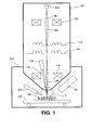
- Figure 1 schematically depicts the particle-optical apparatus according to the invention, in which the particle beam irradiates the sample and a detector detects electromagnetic radiation emanating from the sample.
- the enclosure 102 contains the particle source 104 producing a particle beam 106, such as a beam of electrons or ions, along a particle-optical axis 100.
- Particle-optical lenses 108, 110 and particle-optical deflectors 112, 114 manipulate this particle beam 106.
- the focused particle beam 160 leaves the enclosure102 through an aperture 140 (shown in figure 1A).
- the particle beam 160 irradiates the sample 118 in a scanning fashion.
- the sample 118 is located on a movable sample holder 120, with which the sample is positioned such that the particle beam 160 may scan an area of interest on the sample.
- a detector 124 detects secondary electrons emanating from the sample.
- a gas source 126 admits gas, such as water vapour, to the vicinity of the sample.
- Sample 118, sample holder 120, detector 124 and gas source 126 are enclosed in a vacuum chamber 122.
- the inside of enclosure 102 is kept at a vacuum of e.g. 10 -3 mbar and the inside of vacuum chamber 122 is kept at a vacuum of e.g. 10 mbar by vacuum pumps (not shown).
- Figure 1A shows detail of area I of figure 1, showing the sample end 130 of the enclosure 102, in which the particle beam 160 passes through aperture 140 and in which electromagnetic radiation 170, emanating from the sample 118, passes through a window 150.
- the window 150 is adjacent to aperture 140, so that radiation emanating from the area of interest (as defined by the scanning of particle beam 160) can pass through it.
- the electromagnetic radiation 170 coming from the sample 118 passes through the window 150 and is detected by a detector 128 placed inside the enclosure 102.
- detector 128 may be a detector sensitive to light, but it may also be a detector sensitive to X-ray radiation for the detection of X-rays emanating from the sample.
- the kind of radiation to be passed by the window determines what materials may be used in that window (provided the materials are impenetrable to gas).
- materials For visible light e.g. glass can be used, for infrared e.g. germanium and for X-rays a beryllium window can be used.
- e.g. glass is a material that easily charges when irradiated by charged particles.
- the material of the window 150 can be coated with a transparent layer of electrically conductive material, e.g. ITO (Indium Tin Oxide).
- the side of the aperture located at the inside of the enclosure may be at a vacuum compatible with the demands of e.g. the particle source, but that this is not essential to the apparatus according to the invention. It is also possible to have a further pressure reduction from the aperture towards the source by e.g. passing the beam through one or several gas constrictions.
- Figure 2 schematically shows an embodiment of the particle-optical apparatus according to the invention, in which the particle beam and the beam of electromagnetic radiation in the form of a beam of light are mutually coaxial.
- Figure 2 can be thought to be derived from figure 1.
- a mirror 132 placed in the enclosure 102 has a hole 134 to pass the particle beam, while deflecting the beam of light 170 away from the particle-optical axis 100.
- the beam of light 170 then exits the enclosure 102 through a window in the side wall of the enclosure 102, where a detector such as a camera 136 placed outside the enclosure detects said beam 170.
- Figure 2A shows detail of area II depicted in figure 2.
- the window 152 is made of a material transparent to the light emanating from the sample.
- the window 152 has a central hole, said central hole being the aperture 140 and passing the particle beam 160.
- the window 152 completely encircle the aperture 140, nor that the hole be a central hole.
- the embodiment shows a beam of radiation 170 coming from the sample 118, in this and other embodiments likewise a beam of radiation in the form of e.g. infrared, light or UV can be focused onto the sample 118.
- Figure 2B shows a detail of area II depicted in figure 2 for another embodiment, in which the particle beam 160 and the beam of light 170 are coaxial and in which the material of the window 154 is shaped as a lens.
- the material of the window 154 has a central hole, said hole being the aperture 140.
- the material of the window 152 acts as a lens, thereby focusing the beam of light 170. This has the advantage that the lens is positioned close to the sample, resulting in a better optical performance.
- the lens of the window 154 can be part of an optical microscope, but can also be part of an illumination system, such as a laser illumination system.
- Figure 2C shows a detail of area II depicted in figure 2 for still another embodiment, in which the particle beam and the beam of electromagnetic radiation are coaxial and in which a metal tube surrounds the particle beam.
- a metal tube 173 is inserted in the central hole of the lens 154, said tube acting as gas constriction. Because the metal tube 173 is electrically conductive, charging of the lens material does not influence the particle beam 160. Because of the elongated form of the tube 173, it constitutes a large gas constriction and thus a low gas leakage is realized.
- Figure 2D shows a detail of area II depicted in figure 2, in which the material of the window is formed as an off-axis part of a lens. Because the material of the window 156 is an off-axis part of a lens, beam 170 is deflected away from the particle-optical axis 100. This enables an apparatus in which the mirror 132, shown in figure 2, does not intersect the particle-optical axis, and thus no hole 134 in the mirror is needed to pass the particle beam. For certain applications the mirror 134 may even be eliminated.
- a second window 196 for the transmission of light produced by a LED (Light Emitting Diode) 198 illuminating the sample 118.
- LED Light Emitting Diode
- the LED 198 passing light through the second window 196 may not be essential for the illumination of the sample 118: when light is present anywhere in the vacuum chamber 122 (said chamber made of e.g. stainless steel), sufficient light may illuminate the sample 118 by reflections, in which case the second window 196 can be omitted.
- the part of the enclosure facing the sample may be part of the e.g. magnetic lens of the particle-optical column.
- the holes in said lens influence the magnetic path of the lens: it introduces a multipole field superimposed on the axial field focusing the particle beam 160.
- the presence of the high-order multipole field caused by such a ring of holes gives a lower disturbance at the axis 100 than an asymmetrically distributed array of holes, the latter being inevitable when one asymmetrically placed window 196 is used.
- Figure 3 schematically illustrates the apparatus according to the invention, showing a LVSEM with a particle-optical lens of the immersion type.
- Figure 3 can be thought of as being derived from figure 2.
- Figure 3 shows a lens coil 111 generating a magnetic field.
- the sample end 130 of the enclosure being made of a material with a high magnetic permeability, is part of (the magnetic path of) the particle-optical lens.
- the sample 118 is thus immersed in a magnetic field, which focuses the beam 160.
- this type of particle-optical lens is named an immersion lens.
- particle-optical immersion lenses can immerse the sample in a magnetic field, an electrostatic field, or both. Only the magnetic variant is shown here.
- SED secondary electron detector
- the window 156 is shaped as an off-axis part of a lens.
- a metal tube 173 is inserted in a hole in the window 156, thus forming an aperture 140 to pass the particle beam 160.
- Secondary electrons 161 emanating from the sample 118 are guided through the aperture 140 into the enclosure 102.
- bias means not shown the sample 118 has a small electric bias with respect to the metal tube 173 (bias means not shown).
- these secondary electrons 161 are manipulated (thus: accelerated, focused and/or deflected) and detected by the secondary electron detector 125 (shown in figure 3), as is the case in normal immersion type electron microscopes.
- a beam of light 170 coming from the sample 118 is deflected from the particle-optical axis 100 by the off-axis lens156.
- the metal tube 173 also acts as a gas constriction with a low gas conductance.
- the gas leakage from the sample side 130 of the enclosure towards the inside of the enclosure is thus rather limited. This enables the inside of the enclosure to be kept at a pressure of e.g. 10 -3 mbar, while the sample region is kept at a pressure of e.g. 20 mbar, with pumping means (not shown) as known to one skilled in the art of LVSEM technology.
Landscapes
- Chemical & Material Sciences (AREA)
- Analytical Chemistry (AREA)
- Analysing Materials By The Use Of Radiation (AREA)
Priority Applications (1)
| Application Number | Priority Date | Filing Date | Title |
|---|---|---|---|
| EP05076151A EP1724809A1 (fr) | 2005-05-18 | 2005-05-18 | Appareil optique à particules d'irradiation d' un échantillon |
Applications Claiming Priority (1)
| Application Number | Priority Date | Filing Date | Title |
|---|---|---|---|
| EP05076151A EP1724809A1 (fr) | 2005-05-18 | 2005-05-18 | Appareil optique à particules d'irradiation d' un échantillon |
Publications (1)
| Publication Number | Publication Date |
|---|---|
| EP1724809A1 true EP1724809A1 (fr) | 2006-11-22 |
Family
ID=35058288
Family Applications (1)
| Application Number | Title | Priority Date | Filing Date |
|---|---|---|---|
| EP05076151A Withdrawn EP1724809A1 (fr) | 2005-05-18 | 2005-05-18 | Appareil optique à particules d'irradiation d' un échantillon |
Country Status (1)
| Country | Link |
|---|---|
| EP (1) | EP1724809A1 (fr) |
Cited By (16)
| Publication number | Priority date | Publication date | Assignee | Title |
|---|---|---|---|---|
| EP1956632A1 (fr) * | 2007-02-14 | 2008-08-13 | FEI Company | Appareil optique corpusculaire pour l'observation simultanée d'un échantillon avec des particules et des photons |
| EP2105944A1 (fr) * | 2008-03-28 | 2009-09-30 | FEI Company | "Cellule environnementale" pour appareil optique à particules chargées |
| WO2009138134A1 (fr) * | 2008-05-15 | 2009-11-19 | Carl Zeiss Nts Gmbh | Appareil à faisceau de particules présentant un dispositif de nettoyage |
| EP1956633A3 (fr) * | 2007-02-06 | 2009-12-16 | FEI Company | Appareil optique corpusculaire pour l'observation simultanée d'un échantillon avec des particules et des photons |
| DE102010011898A1 (de) * | 2010-03-18 | 2011-09-22 | Carl Zeiss Nts Gmbh | Inspektionssystem |
| DE102011005732A1 (de) * | 2011-03-17 | 2012-09-20 | Carl Zeiss Microlmaging Gmbh | Einrichtung zur Röntgenspektroskopie |
| US8299432B2 (en) | 2008-11-04 | 2012-10-30 | Fei Company | Scanning transmission electron microscope using gas amplification |
| EP2482061A3 (fr) * | 2011-01-30 | 2013-09-04 | FEI Company | Système et procédé pour la localisation de grands nombres de marqueurs fluorescents dans des échantillons biologiques |
| US8648301B2 (en) | 2011-09-22 | 2014-02-11 | Carl Zeiss Microscopy Ltd. | Particle beam system having a hollow light guide |
| US8921811B2 (en) | 2007-02-06 | 2014-12-30 | Fei Company | High pressure charged particle beam system |
| WO2015044665A1 (fr) * | 2013-09-25 | 2015-04-02 | Oxford Instruments Nanotechnology Tools Limited | Analyse aux rayons x dans l'air |
| CN104810230A (zh) * | 2014-01-27 | 2015-07-29 | Fei公司 | 相关光学和带电粒子显微镜 |
| EP2975630A1 (fr) * | 2014-07-17 | 2016-01-20 | FEI Company | Lentille électrostatique transmissive pour des émissions d'un échantillon |
| CN106525845A (zh) * | 2016-10-11 | 2017-03-22 | 聚束科技(北京)有限公司 | 一种带电粒子束系统、光电联合探测系统及方法 |
| US9679741B2 (en) | 2010-11-09 | 2017-06-13 | Fei Company | Environmental cell for charged particle beam system |
| CN113272932A (zh) * | 2018-12-31 | 2021-08-17 | Asml荷兰有限公司 | 用于在带电粒子装置中进行光学测量的装置 |
Citations (4)
| Publication number | Priority date | Publication date | Assignee | Title |
|---|---|---|---|---|
| US3800152A (en) * | 1970-12-11 | 1974-03-26 | Onera (Off Nat Aerospatiale) | Electron analysis apparatus with heat-protective shield means spacedly overlying a sample supporting surface |
| US5362964A (en) * | 1993-07-30 | 1994-11-08 | Electroscan Corporation | Environmental scanning electron microscope |
| US5598002A (en) * | 1993-08-26 | 1997-01-28 | Hitachi, Ltd. | Electron beam apparatus |
| US20030102436A1 (en) * | 2000-03-20 | 2003-06-05 | Gerard Benas-Sayag | Column simultaneously focusing a particle beam and an optical beam |
-
2005
- 2005-05-18 EP EP05076151A patent/EP1724809A1/fr not_active Withdrawn
Patent Citations (4)
| Publication number | Priority date | Publication date | Assignee | Title |
|---|---|---|---|---|
| US3800152A (en) * | 1970-12-11 | 1974-03-26 | Onera (Off Nat Aerospatiale) | Electron analysis apparatus with heat-protective shield means spacedly overlying a sample supporting surface |
| US5362964A (en) * | 1993-07-30 | 1994-11-08 | Electroscan Corporation | Environmental scanning electron microscope |
| US5598002A (en) * | 1993-08-26 | 1997-01-28 | Hitachi, Ltd. | Electron beam apparatus |
| US20030102436A1 (en) * | 2000-03-20 | 2003-06-05 | Gerard Benas-Sayag | Column simultaneously focusing a particle beam and an optical beam |
Cited By (35)
| Publication number | Priority date | Publication date | Assignee | Title |
|---|---|---|---|---|
| EP1956633A3 (fr) * | 2007-02-06 | 2009-12-16 | FEI Company | Appareil optique corpusculaire pour l'observation simultanée d'un échantillon avec des particules et des photons |
| US8921811B2 (en) | 2007-02-06 | 2014-12-30 | Fei Company | High pressure charged particle beam system |
| US7718979B2 (en) | 2007-02-06 | 2010-05-18 | Fei Company | Particle-optical apparatus for simultaneous observing a sample with particles and photons |
| EP1956632A1 (fr) * | 2007-02-14 | 2008-08-13 | FEI Company | Appareil optique corpusculaire pour l'observation simultanée d'un échantillon avec des particules et des photons |
| CN101545874B (zh) * | 2008-03-28 | 2013-09-25 | Fei公司 | 用于粒子光学设备的环境室 |
| EP2105943A3 (fr) * | 2008-03-28 | 2011-05-11 | Fei Company | Cellule environnementale pour appareil optique corpusculaire |
| US8093558B2 (en) | 2008-03-28 | 2012-01-10 | Fei Company | Environmental cell for a particle-optical apparatus |
| US8658974B2 (en) | 2008-03-28 | 2014-02-25 | Fei Company | Environmental cell for a particle-optical apparatus |
| EP2105944A1 (fr) * | 2008-03-28 | 2009-09-30 | FEI Company | "Cellule environnementale" pour appareil optique à particules chargées |
| US8283641B2 (en) | 2008-05-15 | 2012-10-09 | Carl Zeiss Nts Gmbh | Positioning device for a particle beam apparatus |
| WO2009138134A1 (fr) * | 2008-05-15 | 2009-11-19 | Carl Zeiss Nts Gmbh | Appareil à faisceau de particules présentant un dispositif de nettoyage |
| US8299432B2 (en) | 2008-11-04 | 2012-10-30 | Fei Company | Scanning transmission electron microscope using gas amplification |
| DE102010011898A1 (de) * | 2010-03-18 | 2011-09-22 | Carl Zeiss Nts Gmbh | Inspektionssystem |
| US9679741B2 (en) | 2010-11-09 | 2017-06-13 | Fei Company | Environmental cell for charged particle beam system |
| US9040909B2 (en) | 2011-01-30 | 2015-05-26 | Fei Company | System and method for simultaneous detection of secondary electrons and light in a charged particle beam system |
| EP2482061A3 (fr) * | 2011-01-30 | 2013-09-04 | FEI Company | Système et procédé pour la localisation de grands nombres de marqueurs fluorescents dans des échantillons biologiques |
| US9494516B2 (en) | 2011-01-30 | 2016-11-15 | Fei Company | System and method for simultaneous detection of secondary electrons and light in a charged particle beam system |
| DE102011005732A1 (de) * | 2011-03-17 | 2012-09-20 | Carl Zeiss Microlmaging Gmbh | Einrichtung zur Röntgenspektroskopie |
| DE102011005732B4 (de) * | 2011-03-17 | 2013-08-22 | Carl Zeiss Microscopy Gmbh | Einrichtung zur Röntgenspektroskopie |
| US8648301B2 (en) | 2011-09-22 | 2014-02-11 | Carl Zeiss Microscopy Ltd. | Particle beam system having a hollow light guide |
| US10354834B2 (en) | 2013-09-25 | 2019-07-16 | Oxford Instruments Nanotechnology Tools Limited | X-ray analysis in air |
| US9704688B2 (en) | 2013-09-25 | 2017-07-11 | Oxford Instruments Nanotechnology Tools Limited | X-ray analysis in air |
| WO2015044665A1 (fr) * | 2013-09-25 | 2015-04-02 | Oxford Instruments Nanotechnology Tools Limited | Analyse aux rayons x dans l'air |
| CN104810230B (zh) * | 2014-01-27 | 2017-03-08 | Fei 公司 | 相关光学和带电粒子显微镜 |
| US9293297B2 (en) | 2014-01-27 | 2016-03-22 | Fei Company | Correlative optical and charged particle microscope |
| JP2015141899A (ja) * | 2014-01-27 | 2015-08-03 | エフ イー アイ カンパニFei Company | 補正光学及び荷電粒子顕微鏡 |
| EP2899743A1 (fr) * | 2014-01-27 | 2015-07-29 | Fei Company | Microscopie à particules chargées et optique corrélatives |
| CN104810230A (zh) * | 2014-01-27 | 2015-07-29 | Fei公司 | 相关光学和带电粒子显微镜 |
| US9349564B2 (en) | 2014-07-17 | 2016-05-24 | Fei Company | Charged-particle lens that transmits emissions from sample |
| EP2975630A1 (fr) * | 2014-07-17 | 2016-01-20 | FEI Company | Lentille électrostatique transmissive pour des émissions d'un échantillon |
| CN106525845A (zh) * | 2016-10-11 | 2017-03-22 | 聚束科技(北京)有限公司 | 一种带电粒子束系统、光电联合探测系统及方法 |
| CN106525845B (zh) * | 2016-10-11 | 2023-11-03 | 聚束科技(北京)有限公司 | 一种带电粒子束系统、光电联合探测系统及方法 |
| CN113272932A (zh) * | 2018-12-31 | 2021-08-17 | Asml荷兰有限公司 | 用于在带电粒子装置中进行光学测量的装置 |
| US20220084777A1 (en) * | 2018-12-31 | 2022-03-17 | Asml Netherlands B.V. | Apparatus for obtaining optical measurements in a charged particle apparatus |
| US12451321B2 (en) * | 2018-12-31 | 2025-10-21 | Asml Netherlands B.V. | Apparatus for obtaining optical measurements in a charged particle apparatus |
Similar Documents
| Publication | Publication Date | Title |
|---|---|---|
| US11087955B2 (en) | System combination of a particle beam system and a light-optical system with collinear beam guidance, and use of the system combination | |
| US7718979B2 (en) | Particle-optical apparatus for simultaneous observing a sample with particles and photons | |
| EP1724809A1 (fr) | Appareil optique à particules d'irradiation d' un échantillon | |
| JP3786875B2 (ja) | 帯電粒子ビームデバイスのための対物レンズ | |
| JP5534646B2 (ja) | 粒子ビーム及び光を用いる顕微鏡で試料を観察する装置 | |
| US9874524B2 (en) | In-situ spatially resolved plasma monitoring by using optical emission spectroscopy | |
| EP2061067A2 (fr) | Dispositif de faisceau et système comportant un système de faisceau à particules et microscope optique | |
| EP2899743B1 (fr) | Microscopie à particules chargées et optique corrélative | |
| JP5842308B2 (ja) | 複合顕微鏡装置 | |
| US4810879A (en) | Charged particle energy analyzer | |
| EP1956632A1 (fr) | Appareil optique corpusculaire pour l'observation simultanée d'un échantillon avec des particules et des photons | |
| JP7278983B2 (ja) | マルチビーム走査透過荷電粒子顕微鏡 | |
| CN113471044A (zh) | 具有电子能量损失光谱检测器的透射带电粒子显微镜 | |
| CN114730684A (zh) | 阴极射线发光电子显微镜 | |
| KR102029869B1 (ko) | 탈착가능한 전자현미경용 시료실 장치 및 이를 포함하는 전자현미경 | |
| JP4354197B2 (ja) | 走査電子顕微鏡 | |
| CN115346850A (zh) | 具有偏转单元的粒子束装置 | |
| US9018581B2 (en) | Transmission electron microscope | |
| EP3176808A1 (fr) | Procédé de détection de particules chargées et dispositif à faisceau de particules pour mettre en oeuvre le procédé | |
| US5506414A (en) | Charged-particle analyzer | |
| CN109904053A (zh) | 具有改进eels/eftem模块的透射带电粒子显微镜 | |
| US7009177B1 (en) | Apparatus and method for tilted particle-beam illumination | |
| Minami et al. | High resolution projection X-ray microscope equipped with fluorescent X-ray analyzer and its applications | |
| KR101615513B1 (ko) | 하전입자 빔 정렬 장치 및 이의 이용방법 | |
| CZ304659B6 (cs) | Způsob detekce signálních elektronů v elektronovém mikroskopu a zařízení pro provádění tohoto způsobu |
Legal Events
| Date | Code | Title | Description |
|---|---|---|---|
| PUAI | Public reference made under article 153(3) epc to a published international application that has entered the european phase |
Free format text: ORIGINAL CODE: 0009012 |
|
| AK | Designated contracting states |
Kind code of ref document: A1 Designated state(s): AT BE BG CH CY CZ DE DK EE ES FI FR GB GR HU IE IS IT LI LT LU MC NL PL PT RO SE SI SK TR |
|
| AX | Request for extension of the european patent |
Extension state: AL BA HR LV MK YU |
|
| AKX | Designation fees paid |
Designated state(s): NL |
|
| REG | Reference to a national code |
Ref country code: DE Ref legal event code: 8566 |
|
| STAA | Information on the status of an ep patent application or granted ep patent |
Free format text: STATUS: THE APPLICATION IS DEEMED TO BE WITHDRAWN |
|
| 18D | Application deemed to be withdrawn |
Effective date: 20070523 |