EP1724925B2 - Commutateur de proximité à ultrasons et procédé de détection d'une surface structurée à l'aide d'ondes ultrasonores - Google Patents
Commutateur de proximité à ultrasons et procédé de détection d'une surface structurée à l'aide d'ondes ultrasonores Download PDFInfo
- Publication number
- EP1724925B2 EP1724925B2 EP06405082A EP06405082A EP1724925B2 EP 1724925 B2 EP1724925 B2 EP 1724925B2 EP 06405082 A EP06405082 A EP 06405082A EP 06405082 A EP06405082 A EP 06405082A EP 1724925 B2 EP1724925 B2 EP 1724925B2
- Authority
- EP
- European Patent Office
- Prior art keywords
- frequency
- ultrasonic
- signals
- alternator
- transmission
- Prior art date
- Legal status (The legal status is an assumption and is not a legal conclusion. Google has not performed a legal analysis and makes no representation as to the accuracy of the status listed.)
- Expired - Lifetime
Links
Images

Classifications
-
- G—PHYSICS
- G01—MEASURING; TESTING
- G01S—RADIO DIRECTION-FINDING; RADIO NAVIGATION; DETERMINING DISTANCE OR VELOCITY BY USE OF RADIO WAVES; LOCATING OR PRESENCE-DETECTING BY USE OF THE REFLECTION OR RERADIATION OF RADIO WAVES; ANALOGOUS ARRANGEMENTS USING OTHER WAVES
- G01S7/00—Details of systems according to groups G01S13/00, G01S15/00, G01S17/00
- G01S7/52—Details of systems according to groups G01S13/00, G01S15/00, G01S17/00 of systems according to group G01S15/00
- G01S7/534—Details of non-pulse systems
-
- G—PHYSICS
- G01—MEASURING; TESTING
- G01S—RADIO DIRECTION-FINDING; RADIO NAVIGATION; DETERMINING DISTANCE OR VELOCITY BY USE OF RADIO WAVES; LOCATING OR PRESENCE-DETECTING BY USE OF THE REFLECTION OR RERADIATION OF RADIO WAVES; ANALOGOUS ARRANGEMENTS USING OTHER WAVES
- G01S15/00—Systems using the reflection or reradiation of acoustic waves, e.g. sonar systems
- G01S15/02—Systems using the reflection or reradiation of acoustic waves, e.g. sonar systems using reflection of acoustic waves
- G01S15/04—Systems determining presence of a target
-
- H—ELECTRICITY
- H03—ELECTRONIC CIRCUITRY
- H03K—PULSE TECHNIQUE
- H03K17/00—Electronic switching or gating, i.e. not by contact-making and –breaking
- H03K17/94—Electronic switching or gating, i.e. not by contact-making and –breaking characterised by the way in which the control signals are generated
- H03K17/945—Proximity switches
-
- H—ELECTRICITY
- H03—ELECTRONIC CIRCUITRY
- H03K—PULSE TECHNIQUE
- H03K2217/00—Indexing scheme related to electronic switching or gating, i.e. not by contact-making or -breaking covered by H03K17/00
- H03K2217/94—Indexing scheme related to electronic switching or gating, i.e. not by contact-making or -breaking covered by H03K17/00 characterised by the way in which the control signal is generated
- H03K2217/94005—Indexing scheme related to electronic switching or gating, i.e. not by contact-making or -breaking covered by H03K17/00 characterised by the way in which the control signal is generated activated by voice or sound
Definitions
- the invention relates to an ultrasonic proximity switch and a method for detecting objects with structured surfaces by means of ultrasound according to the features of patent claims 1 and 6.
- Ultrasonic proximity switches such as in the EP 0 997 747 usually work according to the pulse-echo method.
- an ultrasonic transducer emits in each case a wave packet or a burst of ultrasonic waves. These propagate in accordance with the mostly club-shaped directional characteristic of the ultrasonic transducer with the speed of sound in the room. If the wave packet impinges on an object, the sound waves incident on the surface of the object are partially reflected. As a rule, a part of the reflected sound waves propagates in the direction of the ultrasound transducer. This now acts as a receiver and registers the echo signal.
- the transit time ie the time between the emission and the reception of the burst, is proportional to the distance between the ultrasound transducer and the detected object. Since the ultrasonic transducer or transducer immediately after the oscillation of ultrasonic waves, no echo signals can be detected and evaluated within a so-called. Blind or dead area.
- part of its surface must be oriented so that at least a portion of the sound is reflected back to the transducer.
- An object in the form of a plane plate strongly inclined with respect to the sound axis could cause the sound to be reflected away and no echo signal to arrive at the transducer.
- An object of the present invention is to provide an ultrasonic proximity switch and a method for detecting objects with textured surfaces.
- the proximity switch is designed so that it can transmit and record ultrasonic signals with different frequencies. Within the usable bandwidth of the frequency spectrum, several frequencies are set, with which the ultrasonic transducer can be excited. Preferably, one of these frequencies corresponds to that frequency at which the echo signal reflected by an ideal reflector and detected by the proximity switch or its amplitude, duration or sound energy is maximal.
- the receiving and evaluating device comprises a programmable or changeable digital or analog filter, which is generally designed as a bandpass filter. This can be changed depending on the respective transmission frequency and tuned to this.
- the transmission frequency to be used for individual measurement intervals is determined as a function of the echo signals detected in one or more of the preceding measurement intervals.
- a frequency alternator will be referred to hereafter Device for changing or switching the transmission frequency triggered or caused to specify the ultrasonic transducer in the next measurement interval, a different frequency. If the insufficient signal was due to the patterned surface of the object to be detected, it is likely that the patterned object surface will now reflect the ultrasound burst with changed frequency or wavelength so that a useful echo signal can be detected. Should the echo signal still be insufficient, the next transmission frequency is changed in an analogous manner.
- the evaluation of the echo signals detected by the receiver can take place in different ways.
- the output of the proximity switch can only be triggered as a function of the measurement signal from the respectively current measurement period or additionally as a function of the stored information via measurement signals from one or more of the preceding measurement periods.
- measurement signals are evaluated from approximately three to six measurement intervals, wherein a minimum number of detected echo signals is required for the control of the output. In this way it can be prevented that a single insufficient echo signal, which has arisen as a result of switching to another transmission frequency, could lead to an unwanted change of state at the output of the proximity switch.
- Ultrasonic transducers typically include a piezoceramic disk adhered to an acoustic matching layer with lower acoustic impedance, a damping mass, and a transducer housing. These components are coordinated and connected to one another in such a way that the converter has a pronounced resonance frequency at which the efficiency or the sound power that can be emitted by the transducer is maximum.
- the usable bandwidth of a transducer is significantly influenced by the damping mass and by the nature of the connections of the individual transducer components.
- Certain ultrasonic transducers may have one or more additional secondary resonances in addition to the main resonant frequency.
- the frequency response of ultrasonic transducers can also be temperature-dependent.
- the control of an ultrasonic transducer with different frequencies causes on the one hand the emission of ultrasonic waves with different wavelengths.
- other parameters such as the decay, the directional characteristic including any side lobes and the efficiency of the frequency may depend. It is therefore useful to determine for each type of converter one or more frequency ranges that are suitable for the operation of the converter.
- the possibility of changing the transmission frequency can also be used, for example, to detect objects outside the defined detection range, that is, for example, within a part of the blind region.
- the method can be used not only with proximity switches but also with ultrasonic distance measuring devices.
- FIG. 1 schematically shows an ultrasonic proximity switch 1 in the detection of an object 3.
- the object 3 is a stack of paper.
- An ultrasonic transducer also called transducer 5 for short, or transducer, periodically emits ultrasonic bursts with a first transmission frequency f1.
- the transducer 5 has, inter alia, at this frequency f1 a pronounced directional characteristic:
- the sound waves propagate within a narrow opening angle of, for example, about 15 ° in the direction of the acoustic axis A. They meet laterally on one end face of the paper stack and are reflected at this largely.
- This lateral surface or end face of the paper stack has a periodic structure, which is determined by the thickness of the individual sheets.
- the front side may have a superimposed three-dimensional structure, which results from the fact that the individual sheet edges are not exactly congruent to each other, but partially offset slightly in one or two dimensions and / or are arranged rotated to each other.
- This structure can be random or periodic.
- the paper stack is oriented so that the end face facing the transducer 5 is approximately vertical to the acoustic axis A. If a sound wave packet of the frequency f1 hits the front side of the object 3, it is reflected back to the transducer 5. This is in FIG. 1 represented by the solid line with the arrows P1 and P2. At another transmission frequency f2, it may be that only an insufficiently small part of the sound is reflected back to the transducer 5.
- FIG. 1 the broken line with the arrows P3 and P4 symbolically shows the different reflection properties of a structured object surface compared to a smooth object surface.
- the FIGS. 2 and 3 each show a diagram with the frequency responses of two different transducers 5.
- at least one of the operating frequencies f i is equal to one of the resonant frequencies fr j , where the index j is again a natural number.
- the main resonant frequency fr 1 of a transducer 5 is typically greater than about 40kHz and less than about 800kHz.
- the resonance frequency fr 1 may be, for example, about 300 kHz and the bandwidth may be about +/- 50 kHz. At a speed of 340m / s, this corresponds approximately to a wavelength range of 1.36mm to 0.97mm.
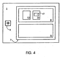
- FIG. 4 shows a simplified block diagram of an ultrasonic proximity switch 1 with the converter 5 and an electronic control 7.
- the controller 7 comprises a transmitting device 9 and a receiving and evaluating device 11.
- the transmitting device 9 comprises a frequency generator 13 and a frequency alternator 15. These can, for example by means of a correspondingly programmed and wired microcontroller (not shown) of the controller 7 can be realized.
- the frequency alternator 15 comprises a memory 17 for storing values of suitable operating frequencies f i or equivalent values which are given to the frequency generator 13 as control variables for generating the respective operating frequency f i .
- the memory 17 may preferably store further parameters associated with each of the operating frequencies f i , such as values for characterizing the respective sound power level L wi and / or the optimal duty cycle and / or the appropriate number of pulses of a pulse packet and / or the decay time of the converter 5.
- algorithms or rules for calculating operating frequencies can also be stored in the memory 17.
- 15 rules or criteria for the parameterization of the frequency generator 13 are specified in the frequency alternator. For example, a fixed order of the operating frequencies f i and / or a number of measuring intervals, after which a change to the next operating frequency f j is provided, can be specified.
- a signal memory may be provided for storing characteristic values for or of echo signals such as comparison values and / or measured values for echo amplitude, echo duration or echo propagation time.
- the frequency alternator 15 - preferably starting with the main resonance frequency f r1 - changes in accordance with a predetermined cyclical order after each measurement interval to the next transmission frequency f i .
- the associated transmission frequency f i is maintained for the subsequent, for example, 10 intervals. If an echo does not occur within these 10 intervals, the system immediately switches back to the original frequency search.
- a frequency optimization is performed. In this case, a transmission signal with a different frequency f i is generated in each case for a measuring period in accordance with the predetermined sequence.
- the associated transmission frequency f i is determined as the new optimum transmission frequency f i .
- the frequency optimization process continues until all available frequencies f i have been tested. If, after a frequency change, the associated echo signal is insufficiently small or can no longer be detected, it immediately switches back to the previous transmission frequency f i with the strongest echo signal. Once again 10 consecutive echoes have been detected, the frequency optimization process continues with the remaining frequencies f i . After the optimum frequency f i has been determined, it is maintained until, for example, a significantly weaker echo signal can be detected in 3 consecutive measurement intervals. In this case, a switch to the frequency optimization process takes place again.
- analog and / or digital filters can be provided, For example, bandpass filters, which are tuned to the respective transmission frequency f i . Of course, these filters can be tuned to the respective active transmission frequencies. It is further pointed out that instead of a common converter 5 for transmitting and receiving the ultrasonic signals, two independent transducers 5 can also be used.
- the invention is not limited to ultrasonic proximity switches 1, in which the presence of an object within a predetermined switching distance or within a predetermined detection range is detected, but also on ultrasonic distance sensors or ultrasonic proximity sensors, in which from the duration of the echo signal an analog or digital distance signal is calculated and output.
Landscapes
- Engineering & Computer Science (AREA)
- Physics & Mathematics (AREA)
- Radar, Positioning & Navigation (AREA)
- Remote Sensing (AREA)
- Computer Networks & Wireless Communication (AREA)
- General Physics & Mathematics (AREA)
- Acoustics & Sound (AREA)
- Measurement Of Velocity Or Position Using Acoustic Or Ultrasonic Waves (AREA)
- Length Measuring Devices Characterised By Use Of Acoustic Means (AREA)
- Investigating Or Analyzing Materials By The Use Of Ultrasonic Waves (AREA)
Claims (8)
- Détecteur de proximité à ultrasons doté d'au moins un transducteur ultrasonore (5) et d'une commande électronique (7), cette commande (7) comprenant un dispositif émetteur (9) avec un générateur de fréquence (13) qui est conçu pour exciter le transducteur ultrasonore (5) à des intervalles de mesure successifs avec des signaux émetteurs et comprenant un dispositif récepteur et évaluateur (11) conçu pour recevoir et évaluer les signaux de l'écho, caractérisé en ce que la fréquence des signaux émetteurs peut être prédéfinie pour chacun des intervalles de mesure par un alternateur de fréquence (15) comme une fréquence de travail parmi plusieurs, dans l'alternateur de fréquence (15) des prescriptions pouvant être prédéfinies pour le paramétrage de l'alternateur de fréquence (13), une sélection de la fréquence de travail actuelle et un passage à la prochaine fréquence de travail pouvant être définis en fonction des signaux de l'écho détectés dans un ou plusieurs des intervalles de mesure précédents.
- Détecteur de proximité à ultrasons, selon la revendication 1, caractérisé en ce que l'alternateur de fréquences (15) comprend une mémoire (17) pour stocker plusieurs fréquences de travail fi différentes ou pour stocker des instructions ou des algorithmes pour le calcul de telles fréquences de travail fi différentes.
- Détecteur de proximité à ultrasons, selon la revendication 2, caractérisé en ce que d'autres paramètres correspondant à chaque fréquence d'émission stockée peuvent être stockés dans la mémoire (17).
- Détecteur de proximité à ultrasons, selon une des revendications 1 à 3, dans lequel le dispositif de réception et d'évaluation (11) comprend un filtre variable, caractérisé en ce que les propriétés du filtre sont variables en fonction de la fréquence d'émission respective prédéfinie par l'alternateur de fréquences (15).
- Procédé permettant de détecter des surfaces structurées d'objets comprenant les étapes suivantes :- des signaux ultrasonores sont émis par un transducteur ultrasonore (5) à des intervalles de mesure successifs,- les échos de ces signaux ultrasonores réfléchis par les objets (3) sont détectés et évalués,- la fréquence des signaux émetteurs est prédéfinie pour chacun des intervalles de mesure par un alternateur de fréquence (15) comme une fréquence de travail parmi plusieurs au sein du spectre de fréquence utile du transducteur ultrasonore (5),- dans l'alternateur de fréquence (15), des prescriptions étant prédéfinies pour le paramétrage du générateur de fréquence (13),- une sélection de la fréquence de travail actuelle et un passage à la prochaine fréquence de travail pouvant être définis en fonction des signaux de l'écho détectés dans un ou plusieurs des intervalles de mesure précédents.
- Procédé selon la revendication 5, caractérisé en ce que plusieurs fréquences de travail sont définies à l'intérieur du spectre de fréquences du transducteur (5), et que la commutation de la fréquence d'émission entre ces fréquences de travail a lieu en fonction de l'intensité des signaux d'écho.
- Procédé selon la revendication 6, caractérisé en ce que des informations sur l'intensité des signaux d'écho sont stockées, et que ces informations stockées sont utilisées pour la détermination de la fréquence d'émission appropriée.
- Procédé selon une des revendications 5 à 7, dans lequel les signaux ultrasonores détectés sont filtrés par un filtre variable, caractérisé en ce que les propriétés du filtre sont variables en fonction de la fréquence d'émission.
Applications Claiming Priority (1)
| Application Number | Priority Date | Filing Date | Title |
|---|---|---|---|
| CH8472005 | 2005-05-13 |
Publications (3)
| Publication Number | Publication Date |
|---|---|
| EP1724925A1 EP1724925A1 (fr) | 2006-11-22 |
| EP1724925B1 EP1724925B1 (fr) | 2010-01-20 |
| EP1724925B2 true EP1724925B2 (fr) | 2012-11-28 |
Family
ID=36950111
Family Applications (1)
| Application Number | Title | Priority Date | Filing Date |
|---|---|---|---|
| EP06405082A Expired - Lifetime EP1724925B2 (fr) | 2005-05-13 | 2006-02-27 | Commutateur de proximité à ultrasons et procédé de détection d'une surface structurée à l'aide d'ondes ultrasonores |
Country Status (3)
| Country | Link |
|---|---|
| EP (1) | EP1724925B2 (fr) |
| AT (1) | ATE456190T1 (fr) |
| DE (1) | DE502006005953D1 (fr) |
Families Citing this family (2)
| Publication number | Priority date | Publication date | Assignee | Title |
|---|---|---|---|---|
| CN110492878B (zh) * | 2019-08-08 | 2020-12-01 | 厦门大学 | 一种小型水下亚波长声学开关装置 |
| EP4060378B1 (fr) | 2021-03-17 | 2026-04-22 | Hyundai Mobis Co., Ltd. | Système de commande de capteur à ultrasons pour véhicule et procédé de commande |
Citations (2)
| Publication number | Priority date | Publication date | Assignee | Title |
|---|---|---|---|---|
| EP0116901A2 (fr) † | 1983-02-10 | 1984-08-29 | DEUTSCHE FORSCHUNGSANSTALT FÜR LUFT- UND RAUMFAHRT e.V. | Appareil de contrôle ultrasonore |
| DE3710239A1 (de) † | 1987-03-27 | 1988-10-06 | Siemens Ag | Verfahren zur objekterfassung |
Family Cites Families (3)
| Publication number | Priority date | Publication date | Assignee | Title |
|---|---|---|---|---|
| EP0997747B1 (fr) * | 1998-10-20 | 2005-04-13 | Siemens Aktiengesellschaft | Méthode pour optimiser l'opération d'un commutateur de proximité et commutateur de proximité à opération optimisée |
| DE10114819A1 (de) * | 2001-03-26 | 2002-10-10 | Siemens Ag | Verfahren zur Verbesserung des Signalempfangs eines Ultraschall-Näherungsschalters und Ultraschall-Näherungsschalter mit verbessertem Signalempfang |
| US7313053B2 (en) * | 2003-03-06 | 2007-12-25 | General Electric Company | Method and apparatus for controlling scanning of mosaic sensor array |
-
2006
- 2006-02-27 DE DE502006005953T patent/DE502006005953D1/de not_active Expired - Lifetime
- 2006-02-27 AT AT06405082T patent/ATE456190T1/de active
- 2006-02-27 EP EP06405082A patent/EP1724925B2/fr not_active Expired - Lifetime
Patent Citations (2)
| Publication number | Priority date | Publication date | Assignee | Title |
|---|---|---|---|---|
| EP0116901A2 (fr) † | 1983-02-10 | 1984-08-29 | DEUTSCHE FORSCHUNGSANSTALT FÜR LUFT- UND RAUMFAHRT e.V. | Appareil de contrôle ultrasonore |
| DE3710239A1 (de) † | 1987-03-27 | 1988-10-06 | Siemens Ag | Verfahren zur objekterfassung |
Also Published As
| Publication number | Publication date |
|---|---|
| EP1724925B1 (fr) | 2010-01-20 |
| EP1724925A1 (fr) | 2006-11-22 |
| DE502006005953D1 (de) | 2010-03-11 |
| ATE456190T1 (de) | 2010-02-15 |
Similar Documents
| Publication | Publication Date | Title |
|---|---|---|
| EP0326623B1 (fr) | Procédé pour détecter la position d'un obstacle | |
| DE102010021960B4 (de) | Verrfahren zum Erkennen eines blockierten Zustands eines Ultraschallsensors eines Kraftfahrzeugs, Fahrerassistenzeinrichtung und Kraftfahrzeug | |
| DE102009061087B3 (de) | Ultraschallsensor | |
| EP1058126B1 (fr) | Dispositif de détection à distance | |
| EP2430474B1 (fr) | Procédé d'essai de fonctionnement d'un capteur à ultrasons sur un véhicule à moteur, procédé permettant de faire fonctionner un capteur à ultrasons sur un véhicule à moteur, et dispositif de mesure de distance présentant au moins un capteur à ultrasons pour l'utilisation dans un véhicule à moteur | |
| DE3721209C2 (de) | Schall-/Ultraschallmeßgerät | |
| EP0961106A1 (fr) | Dispositif de mesure du niveau de remplissage d'un réservoir | |
| DE3337690A1 (de) | Verfahren und vorrichtung zur messung des fuellstands in einem behaelter mittels schall-/ultraschallwellen | |
| EP1293803B1 (fr) | Procédé de mesure de distance au moyen d'ultrason | |
| DE102016224928A1 (de) | Verfahren zum Betrieb eines Ultraschallsensors | |
| DE3513270A1 (de) | Einrichtung zur abstandsmessung, insbesondere fuer kraftfahrzeuge | |
| EP3574342A1 (fr) | Dispositif à capteurs à ultrasons | |
| EP2639790A1 (fr) | Véhicule sans conducteur comprenant au moins un capteur à ultrasons et procédé de fonctionnement de celui-ci | |
| EP2780737B1 (fr) | Dispositif d'aide à la conduite pour un véhicule automobile, véhicule automobile et procédé de fonctionnement d'un dispositif d'aide à la conduite dans un véhicule automobile | |
| EP2035858A1 (fr) | Capteur a ultrasons, vehicule a moteur le comprenant et procede pour le faire fonctionner | |
| DE60013403T2 (de) | Piezoelektrische flüssigkeitsstands-messvorrichtung | |
| EP1724925B1 (fr) | Commutateur de proximité à ultrasons et procédé de détection d'une surface structurée à l'aide d'ondes ultrasonores | |
| DE4204414C1 (en) | Pulse echo level measuring instrument with pulse transceiver - has circuits to derive distance between transceiver and reflection surface from time between single or multiple echo pulses | |
| DE10225614A1 (de) | Schaltungsanordnung zum Betrieb eines Ultraschall-Abstandssensors | |
| WO1994010533A1 (fr) | Procede et dispositif permettant de determiner sans contact la masse par unite de surface de materiaux minces | |
| DE102006041529B4 (de) | Verfahren zur Entfernungsbestimmung | |
| DE2721254B2 (de) | Schaltungsanordnung für einen Bewegungsdetektor | |
| EP1510487B1 (fr) | Procédé et dispositif de détection de la position d'un bord d'une bande de matériau en mouvement | |
| DE4014990A1 (de) | Vorrichtung zur bestimmung des fluessigkeitsstandes einer fluessigkeit in einem behaelter | |
| WO2024046534A1 (fr) | Procédé et dispositif pour détecter des états de choc et de vibration dans un transducteur magnétostrictif |
Legal Events
| Date | Code | Title | Description |
|---|---|---|---|
| PUAI | Public reference made under article 153(3) epc to a published international application that has entered the european phase |
Free format text: ORIGINAL CODE: 0009012 |
|
| AK | Designated contracting states |
Kind code of ref document: A1 Designated state(s): AT BE BG CH CY CZ DE DK EE ES FI FR GB GR HU IE IS IT LI LT LU LV MC NL PL PT RO SE SI SK TR |
|
| AX | Request for extension of the european patent |
Extension state: AL BA HR MK YU |
|
| 17P | Request for examination filed |
Effective date: 20070423 |
|
| 17Q | First examination report despatched |
Effective date: 20070525 |
|
| AKX | Designation fees paid |
Designated state(s): AT BE BG CH CY CZ DE DK EE ES FI FR GB GR HU IE IS IT LI LT LU LV MC NL PL PT RO SE SI SK TR |
|
| GRAP | Despatch of communication of intention to grant a patent |
Free format text: ORIGINAL CODE: EPIDOSNIGR1 |
|
| GRAS | Grant fee paid |
Free format text: ORIGINAL CODE: EPIDOSNIGR3 |
|
| GRAA | (expected) grant |
Free format text: ORIGINAL CODE: 0009210 |
|
| AK | Designated contracting states |
Kind code of ref document: B1 Designated state(s): AT BE BG CH CY CZ DE DK EE ES FI FR GB GR HU IE IS IT LI LT LU LV MC NL PL PT RO SE SI SK TR |
|
| REG | Reference to a national code |
Ref country code: GB Ref legal event code: FG4D Free format text: NOT ENGLISH |
|
| REG | Reference to a national code |
Ref country code: CH Ref legal event code: EP Ref country code: CH Ref legal event code: NV Representative=s name: GACHNANG AG PATENTANWAELTE |
|
| REG | Reference to a national code |
Ref country code: IE Ref legal event code: FG4D |
|
| REF | Corresponds to: |
Ref document number: 502006005953 Country of ref document: DE Date of ref document: 20100311 Kind code of ref document: P |
|
| REG | Reference to a national code |
Ref country code: NL Ref legal event code: VDEP Effective date: 20100120 |
|
| LTIE | Lt: invalidation of european patent or patent extension |
Effective date: 20100120 |
|
| PG25 | Lapsed in a contracting state [announced via postgrant information from national office to epo] |
Ref country code: LT Free format text: LAPSE BECAUSE OF FAILURE TO SUBMIT A TRANSLATION OF THE DESCRIPTION OR TO PAY THE FEE WITHIN THE PRESCRIBED TIME-LIMIT Effective date: 20100120 Ref country code: IS Free format text: LAPSE BECAUSE OF FAILURE TO SUBMIT A TRANSLATION OF THE DESCRIPTION OR TO PAY THE FEE WITHIN THE PRESCRIBED TIME-LIMIT Effective date: 20100520 Ref country code: ES Free format text: LAPSE BECAUSE OF FAILURE TO SUBMIT A TRANSLATION OF THE DESCRIPTION OR TO PAY THE FEE WITHIN THE PRESCRIBED TIME-LIMIT Effective date: 20100501 Ref country code: NL Free format text: LAPSE BECAUSE OF FAILURE TO SUBMIT A TRANSLATION OF THE DESCRIPTION OR TO PAY THE FEE WITHIN THE PRESCRIBED TIME-LIMIT Effective date: 20100120 Ref country code: PT Free format text: LAPSE BECAUSE OF FAILURE TO SUBMIT A TRANSLATION OF THE DESCRIPTION OR TO PAY THE FEE WITHIN THE PRESCRIBED TIME-LIMIT Effective date: 20100520 |
|
| REG | Reference to a national code |
Ref country code: IE Ref legal event code: FD4D |
|
| BERE | Be: lapsed |
Owner name: BAUMER ELECTRIC A.G. Effective date: 20100228 |
|
| PG25 | Lapsed in a contracting state [announced via postgrant information from national office to epo] |
Ref country code: PL Free format text: LAPSE BECAUSE OF FAILURE TO SUBMIT A TRANSLATION OF THE DESCRIPTION OR TO PAY THE FEE WITHIN THE PRESCRIBED TIME-LIMIT Effective date: 20100120 Ref country code: LV Free format text: LAPSE BECAUSE OF FAILURE TO SUBMIT A TRANSLATION OF THE DESCRIPTION OR TO PAY THE FEE WITHIN THE PRESCRIBED TIME-LIMIT Effective date: 20100120 Ref country code: FI Free format text: LAPSE BECAUSE OF FAILURE TO SUBMIT A TRANSLATION OF THE DESCRIPTION OR TO PAY THE FEE WITHIN THE PRESCRIBED TIME-LIMIT Effective date: 20100120 Ref country code: SI Free format text: LAPSE BECAUSE OF FAILURE TO SUBMIT A TRANSLATION OF THE DESCRIPTION OR TO PAY THE FEE WITHIN THE PRESCRIBED TIME-LIMIT Effective date: 20100120 |
|
| PLBI | Opposition filed |
Free format text: ORIGINAL CODE: 0009260 |
|
| PG25 | Lapsed in a contracting state [announced via postgrant information from national office to epo] |
Ref country code: EE Free format text: LAPSE BECAUSE OF FAILURE TO SUBMIT A TRANSLATION OF THE DESCRIPTION OR TO PAY THE FEE WITHIN THE PRESCRIBED TIME-LIMIT Effective date: 20100120 Ref country code: SE Free format text: LAPSE BECAUSE OF FAILURE TO SUBMIT A TRANSLATION OF THE DESCRIPTION OR TO PAY THE FEE WITHIN THE PRESCRIBED TIME-LIMIT Effective date: 20100120 Ref country code: RO Free format text: LAPSE BECAUSE OF FAILURE TO SUBMIT A TRANSLATION OF THE DESCRIPTION OR TO PAY THE FEE WITHIN THE PRESCRIBED TIME-LIMIT Effective date: 20100120 Ref country code: MC Free format text: LAPSE BECAUSE OF NON-PAYMENT OF DUE FEES Effective date: 20100301 Ref country code: IE Free format text: LAPSE BECAUSE OF FAILURE TO SUBMIT A TRANSLATION OF THE DESCRIPTION OR TO PAY THE FEE WITHIN THE PRESCRIBED TIME-LIMIT Effective date: 20100120 Ref country code: GR Free format text: LAPSE BECAUSE OF FAILURE TO SUBMIT A TRANSLATION OF THE DESCRIPTION OR TO PAY THE FEE WITHIN THE PRESCRIBED TIME-LIMIT Effective date: 20100421 Ref country code: CY Free format text: LAPSE BECAUSE OF FAILURE TO SUBMIT A TRANSLATION OF THE DESCRIPTION OR TO PAY THE FEE WITHIN THE PRESCRIBED TIME-LIMIT Effective date: 20100120 |
|
| PLAX | Notice of opposition and request to file observation + time limit sent |
Free format text: ORIGINAL CODE: EPIDOSNOBS2 |
|
| 26 | Opposition filed |
Opponent name: FIRMA PEPPERL + FUCHS GMBH Effective date: 20101020 |
|
| PG25 | Lapsed in a contracting state [announced via postgrant information from national office to epo] |
Ref country code: CZ Free format text: LAPSE BECAUSE OF FAILURE TO SUBMIT A TRANSLATION OF THE DESCRIPTION OR TO PAY THE FEE WITHIN THE PRESCRIBED TIME-LIMIT Effective date: 20100120 Ref country code: BG Free format text: LAPSE BECAUSE OF FAILURE TO SUBMIT A TRANSLATION OF THE DESCRIPTION OR TO PAY THE FEE WITHIN THE PRESCRIBED TIME-LIMIT Effective date: 20100420 Ref country code: SK Free format text: LAPSE BECAUSE OF FAILURE TO SUBMIT A TRANSLATION OF THE DESCRIPTION OR TO PAY THE FEE WITHIN THE PRESCRIBED TIME-LIMIT Effective date: 20100120 |
|
| GBPC | Gb: european patent ceased through non-payment of renewal fee |
Effective date: 20100420 |
|
| PG25 | Lapsed in a contracting state [announced via postgrant information from national office to epo] |
Ref country code: DK Free format text: LAPSE BECAUSE OF FAILURE TO SUBMIT A TRANSLATION OF THE DESCRIPTION OR TO PAY THE FEE WITHIN THE PRESCRIBED TIME-LIMIT Effective date: 20100120 |
|
| PG25 | Lapsed in a contracting state [announced via postgrant information from national office to epo] |
Ref country code: BE Free format text: LAPSE BECAUSE OF NON-PAYMENT OF DUE FEES Effective date: 20100228 |
|
| PLAF | Information modified related to communication of a notice of opposition and request to file observations + time limit |
Free format text: ORIGINAL CODE: EPIDOSCOBS2 |
|
| PG25 | Lapsed in a contracting state [announced via postgrant information from national office to epo] |
Ref country code: GB Free format text: LAPSE BECAUSE OF NON-PAYMENT OF DUE FEES Effective date: 20100420 |
|
| REG | Reference to a national code |
Ref country code: CH Ref legal event code: NV Representative=s name: BAUMER INNOTEC AG |
|
| PLBB | Reply of patent proprietor to notice(s) of opposition received |
Free format text: ORIGINAL CODE: EPIDOSNOBS3 |
|
| REG | Reference to a national code |
Ref country code: FR Ref legal event code: ST Effective date: 20110502 |
|
| PG25 | Lapsed in a contracting state [announced via postgrant information from national office to epo] |
Ref country code: FR Free format text: LAPSE BECAUSE OF NON-PAYMENT OF DUE FEES Effective date: 20100322 |
|
| PG25 | Lapsed in a contracting state [announced via postgrant information from national office to epo] |
Ref country code: LU Free format text: LAPSE BECAUSE OF NON-PAYMENT OF DUE FEES Effective date: 20100227 Ref country code: HU Free format text: LAPSE BECAUSE OF FAILURE TO SUBMIT A TRANSLATION OF THE DESCRIPTION OR TO PAY THE FEE WITHIN THE PRESCRIBED TIME-LIMIT Effective date: 20100721 |
|
| PUAH | Patent maintained in amended form |
Free format text: ORIGINAL CODE: 0009272 |
|
| STAA | Information on the status of an ep patent application or granted ep patent |
Free format text: STATUS: PATENT MAINTAINED AS AMENDED |
|
| PG25 | Lapsed in a contracting state [announced via postgrant information from national office to epo] |
Ref country code: TR Free format text: LAPSE BECAUSE OF FAILURE TO SUBMIT A TRANSLATION OF THE DESCRIPTION OR TO PAY THE FEE WITHIN THE PRESCRIBED TIME-LIMIT Effective date: 20100120 |
|
| 27A | Patent maintained in amended form |
Effective date: 20121128 |
|
| AK | Designated contracting states |
Kind code of ref document: B2 Designated state(s): AT BE BG CH CY CZ DE DK EE ES FI FR GB GR HU IE IS IT LI LT LU LV MC NL PL PT RO SE SI SK TR |
|
| REG | Reference to a national code |
Ref country code: CH Ref legal event code: AELC |
|
| REG | Reference to a national code |
Ref country code: AT Ref legal event code: MM01 Ref document number: 456190 Country of ref document: AT Kind code of ref document: T Effective date: 20110227 |
|
| REG | Reference to a national code |
Ref country code: DE Ref legal event code: R102 Ref document number: 502006005953 Country of ref document: DE Effective date: 20121128 |
|
| PG25 | Lapsed in a contracting state [announced via postgrant information from national office to epo] |
Ref country code: AT Free format text: LAPSE BECAUSE OF NON-PAYMENT OF DUE FEES Effective date: 20110227 |
|
| PG25 | Lapsed in a contracting state [announced via postgrant information from national office to epo] |
Ref country code: LV Free format text: LAPSE BECAUSE OF FAILURE TO SUBMIT A TRANSLATION OF THE DESCRIPTION OR TO PAY THE FEE WITHIN THE PRESCRIBED TIME-LIMIT Effective date: 20121128 |
|
| REG | Reference to a national code |
Ref country code: DE Ref legal event code: R082 Ref document number: 502006005953 Country of ref document: DE |
|
| PGFP | Annual fee paid to national office [announced via postgrant information from national office to epo] |
Ref country code: IT Payment date: 20190222 Year of fee payment: 14 Ref country code: DE Payment date: 20190219 Year of fee payment: 14 Ref country code: CH Payment date: 20190221 Year of fee payment: 14 |
|
| REG | Reference to a national code |
Ref country code: DE Ref legal event code: R119 Ref document number: 502006005953 Country of ref document: DE |
|
| REG | Reference to a national code |
Ref country code: CH Ref legal event code: PL |
|
| PG25 | Lapsed in a contracting state [announced via postgrant information from national office to epo] |
Ref country code: CH Free format text: LAPSE BECAUSE OF NON-PAYMENT OF DUE FEES Effective date: 20200229 Ref country code: LI Free format text: LAPSE BECAUSE OF NON-PAYMENT OF DUE FEES Effective date: 20200229 |
|
| PG25 | Lapsed in a contracting state [announced via postgrant information from national office to epo] |
Ref country code: DE Free format text: LAPSE BECAUSE OF NON-PAYMENT OF DUE FEES Effective date: 20200901 |
|
| PG25 | Lapsed in a contracting state [announced via postgrant information from national office to epo] |
Ref country code: IT Free format text: LAPSE BECAUSE OF NON-PAYMENT OF DUE FEES Effective date: 20200227 |