EP1725404B1 - Verpackungshülle für einen zylinder in einer druckpresse - Google Patents
Verpackungshülle für einen zylinder in einer druckpresse Download PDFInfo
- Publication number
- EP1725404B1 EP1725404B1 EP05718231A EP05718231A EP1725404B1 EP 1725404 B1 EP1725404 B1 EP 1725404B1 EP 05718231 A EP05718231 A EP 05718231A EP 05718231 A EP05718231 A EP 05718231A EP 1725404 B1 EP1725404 B1 EP 1725404B1
- Authority
- EP
- European Patent Office
- Prior art keywords
- packing sleeve
- cylinder
- voids
- packing
- sleeve
- Prior art date
- Legal status (The legal status is an assumption and is not a legal conclusion. Google has not performed a legal analysis and makes no representation as to the accuracy of the status listed.)
- Expired - Lifetime
Links
- 238000012856 packing Methods 0.000 title claims abstract description 108
- 238000007639 printing Methods 0.000 title claims abstract description 38
- 238000000034 method Methods 0.000 claims description 8
- 238000007493 shaping process Methods 0.000 description 4
- 241000264877 Hippospongia communis Species 0.000 description 3
- 230000007423 decrease Effects 0.000 description 3
- 239000000853 adhesive Substances 0.000 description 2
- 230000001070 adhesive effect Effects 0.000 description 2
- 238000010276 construction Methods 0.000 description 2
- 238000011161 development Methods 0.000 description 2
- 230000018109 developmental process Effects 0.000 description 2
- 238000007645 offset printing Methods 0.000 description 2
- 239000011800 void material Substances 0.000 description 2
- 229910000831 Steel Inorganic materials 0.000 description 1
- 230000008602 contraction Effects 0.000 description 1
- 230000001419 dependent effect Effects 0.000 description 1
- 230000000694 effects Effects 0.000 description 1
- 239000011796 hollow space material Substances 0.000 description 1
- 239000000463 material Substances 0.000 description 1
- 238000011084 recovery Methods 0.000 description 1
- 239000007787 solid Substances 0.000 description 1
- 239000010959 steel Substances 0.000 description 1
Images


Classifications
-
- B—PERFORMING OPERATIONS; TRANSPORTING
- B41—PRINTING; LINING MACHINES; TYPEWRITERS; STAMPS
- B41F—PRINTING MACHINES OR PRESSES
- B41F27/00—Devices for attaching printing elements or formes to supports
- B41F27/10—Devices for attaching printing elements or formes to supports for attaching non-deformable curved printing formes to forme cylinders
- B41F27/105—Devices for attaching printing elements or formes to supports for attaching non-deformable curved printing formes to forme cylinders for attaching cylindrical printing formes
-
- B—PERFORMING OPERATIONS; TRANSPORTING
- B41—PRINTING; LINING MACHINES; TYPEWRITERS; STAMPS
- B41F—PRINTING MACHINES OR PRESSES
- B41F27/00—Devices for attaching printing elements or formes to supports
- B41F27/14—Devices for attaching printing elements or formes to supports for attaching printing formes to intermediate supports, e.g. adapter members
-
- B—PERFORMING OPERATIONS; TRANSPORTING
- B41—PRINTING; LINING MACHINES; TYPEWRITERS; STAMPS
- B41P—INDEXING SCHEME RELATING TO PRINTING, LINING MACHINES, TYPEWRITERS, AND TO STAMPS
- B41P2227/00—Mounting or handling printing plates; Forming printing surfaces in situ
- B41P2227/20—Means enabling or facilitating exchange of tubular printing or impression members, e.g. printing sleeves, blankets
-
- Y—GENERAL TAGGING OF NEW TECHNOLOGICAL DEVELOPMENTS; GENERAL TAGGING OF CROSS-SECTIONAL TECHNOLOGIES SPANNING OVER SEVERAL SECTIONS OF THE IPC; TECHNICAL SUBJECTS COVERED BY FORMER USPC CROSS-REFERENCE ART COLLECTIONS [XRACs] AND DIGESTS
- Y10—TECHNICAL SUBJECTS COVERED BY FORMER USPC
- Y10T—TECHNICAL SUBJECTS COVERED BY FORMER US CLASSIFICATION
- Y10T428/00—Stock material or miscellaneous articles
- Y10T428/13—Hollow or container type article [e.g., tube, vase, etc.]
Definitions
- the invention relates to a packing sleeve for a cylinder in a printing press according to the preamble of claim 1.
- the invention relates furthermore to a method for varying the inner diameter of a packing sleeve.
- DE 197 53 744 shows a packing sleeve.
- sleeve-form cylinder packings also known as packing sleeves
- packing sleeves are often used. So that such packing sleeves are firmly connected during operation to the cylinder receiving them, it is customary to make the inner diameter of the packing sleeve slightly but sufficiently smaller than the outer diameter of the cylinder receiving it, so that in the mounted state the deformation or extension of the packing sleeve produces a dynamic recovery force.
- the inner diameter of the packing sleeve is enlarged by the action of force: a common method is described, for example, in the document US 6,368,100 B .
- a current of air is able to escape from the presenting cylinder such that an air bubble is produced and a dynamic effect is exerted on the packing sleeve in order to extend it. It is preferable to be able to avoid such a complex auxiliary device.
- a packing sleeve suitable for a cylinder, especially a printing plate cylinder, in a printing press comprises an evacuatable structure of voids.
- the packing sleeve can also be called in particular an intermediate sleeve for a printing plate.
- the term void or voids is meant to denote all different kinds of macroscopic openings or macroscopic hollow spaces in the packing sleeve, especially cavities, caverns, hollows, passageways, cells, honeycombs and channels.
- the evacuatable structure of voids and/or the shaping of the voids are/is carried out such that when a negative pressure is generated in the evacuatable structure the inner diameter of the packing sleeve increases and/or the outer diameter of the packing sleeve decreases. In this way, mounting on or demounting from a receiving cylinder that is of slightly larger diameter than the inner diameter of the packing sleeve in the force-free state is facilitated.
- the evacuatable structure can comprise a plurality of individual voids, and/or several voids of the evacuatable structure can be connected with one another.
- the structure can consequently also be referred to as a system or network of voids.
- the voids can run substantially parallel to the figure axis of the packing sleeve, especially the axis of rotation or main axis of the substantially rotationally symmetric packing sleeve.
- the packing sleeve has in its outer lateral surface at least one recess for fixing a plate-form cylinder packing.
- the packing sleeve has at its inner lateral surface at least one recess or one projection.
- Such recesses or projections are provided for correspondingly inversely formed projections or recesses on the receiving cylinder, so that fixing of the packing sleeve, especially in the azimuthal direction, can be achieved.
- the packing sleeve according to the invention comprises at least one annular lateral plate, which comprises a cavity or a hollow space connected with the evacuatable structure.
- An evacuating device for example a vacuum pump, can be connected to this cavity.
- Linked to the inventive concept is also a method for varying the internal diameter of a packing sleeve, as is disclosed in this description.
- a negative pressure is applied to the evacuatable structure of the packing sleeve.
- the method according to the invention can be carried out during a change in the fixing state of the packing sleeve on a cylinder in a printing press, the inner diameter of the packing sleeve being increased by the application of negative pressure.
- the mounting or demounting of the packing sleeve on a cylinder having an outer diameter that is slightly larger than the inner diameter of the packing sleeve in the force-free state (with no negative pressure being applied) is thereby advantageously facilitated or simplified.
- the packing sleeve according to the invention can advantageously be used to increase the effective diameter or the effective circumferential length of a cylinder in a printing press, especially a printing plate cylinder.
- associated with the concept of the invention is the use according to the invention of a packing sleeve according to this description for increasing the outer diameter of a cylinder in a printing press, by drawing the packing sleeve over the cylinder in the printing press.
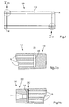
- Figure 1 shows a schematic representation of an embodiment of a packing sleeve according to the invention together with details in Fig. 1 a and Fig. 1 b.
- the packing sleeve 10 according to the invention comprises a tube 12, at each end of which a lateral plate 14 in the form of a ring is arranged, so that the packing sleeve 10 can be drawn over a receiving cylinder substantially parallel to the figure axis thereof. Fixing of the lateral plates 14 to the tube 12 can be effected by an adhesive joint 20.
- the details of Fig 1 a and Fig.1b show respective enlarged cutouts.
- the tube 12 is seen to have an evacuatable structure of voids 16, which run substantially parallel to the figure axis of the packing sleeve 10. These voids 16 are connected to a cavity 18 in the lateral plate 14.
- the lateral plate 14 has a chamfer of small angle 22.
- An evacuating means for example, a vacuum pump, can be connected to an opening 24 in order to create a negative pressure in the evacuatable structure of voids 16. This negative pressure causes a contraction, i.e. the decrease in the outer diameter and the increase in the inner diameter (see also Fig. 5 ) of the packing sleeve 10, typically by 1 to 2 hundredths of a millimetre.
- Fig. 5 the detail of Fig.
- the lateral plate 14 is seen to have a cavity 18 that connects the voids 16 of the evacuatable structure.
- a material having a low modulus of elasticity is used, so that mounting on or demounting from a receiving cylinder is facilitated.
- the packing sleeve preferably advantageously also has a coefficient of thermal expansion slightly lower than that of the steel of the receiving cylinder.
- the packing sleeve 10 In the state under a negative pressure, that is, when the inner diameter is enlarged, the packing sleeve 10 can be easily and conveniently received on a cylinder or removed from the cylinder.
- the small angle 22 mentioned helps to position the extreme regions of the packing sleeve 10 in the printing press. Since the outer diameter is reduced, a printing plate, can be easily and conveniently mounted or demounted. A plate-form printing plate can be fixed on the packing sleeve 10 away from the printing press, prior to mounting of the packing sleeve 10. The printing plate is then held under tension on the packing sleeve 10 when evacuation of the voids 16 terminates. A special, often complex printing plate-holding and/or printing plate-clamping device is no longer necessary.
- packing sleeves according to the invention can be supplied in different formats (outer diameters), so that different printing lengths can be realised with a printing press having cylinders of a specific fixed format.
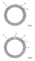
- FIG. 2 illustrates an embodiment of a packing sleeve 10 for a blanket cylinder.
- This packing sleeve 10 comprises a regular structure 26 of voids 16.
- the voids 16, here having a stadium-shaped cross-sectional area, run substantially parallel to the axis of rotational symmetry of the packing sleeve 10.
- Such a regular structure 26 can also be called a honeycomb structure.
- FIG 3 is a schematic illustration relating to an embodiment of a packing sleeve 10 according to the invention for a printing plate cylinder. Akin to the embodiment shown in Figure 2 , this packing sleeve also has a honeycomb structure. A trapezoidal recess 28, which serves to receive bent-over edges of a plate-form printing plate, is provided in the outer lateral surface 30. The bent-over edges can be introduced into the recess 28 when the packing sleeve 10 is under a negative pressure.
- FIG 4 is a schematic partial view of an alternative embodiment of a packing sleeve 10 according to the invention with an evacuatable structure of voids 16 for a printing plate cylinder.
- a trapezoidal recess 28 as shown in Figure 3 , in this embodiment a V-shaped recess 32 for receiving the bent-over edges or a printing plate is provided.
- the web between the arms of the V-shaped recess additionally stabilises the position of the bent-over edges in the recess.
- Figure 5 shows a schematic representation for explanation of the deformation behaviour when the packing sleeve 10 according to the invention is evacuated.
- a cut-out of an embodiment of a packing sleeve 10 according to the invention is shown in two states: the broken outline represents the undeformed packing sleeve 10, that is, the undeformed state 34, the solid outline shows the packing sleeve 10 deformed by evacuation of the voids 16, that is, the deformed state 36.
- the evacuatable structure of the voids 16 is selected or constructed so that both a decrease in the inner diameter and an increase in the inner diameter are achieved.
- Figure 6 shows schematically two cylinders on which more sophisticated embodiments of the packing sleeve according to the invention can be received.
- recesses or projections can be arranged at the inner lateral surface of the packing sleeve.
- These shapings then correspond to inverse shapings on the receiving cylinder.
- the upper part of Figure 6 shows by way of example a cylinder 42 receiving a packing sleeve 10 according to the invention, the cylinder having stops 44 on its outer lateral surface, here three stops distributed uniformly around the full circle. These stops 44 project beyond the outer lateral surface of the cylinder 42 and engage in recesses, not shown here, at the inner lateral surface of a packing sleeve 10 according to the invention to be received on the cylinder.
- FIG. 6 shows, as an alternative or in addition to the projections already described, that a cylinder 42 receiving a packing sleeve 10 according to the invention can have recesses 46 arranged on the outer lateral surface, here three recesses distributed uniformly around the full circle. These recesses 46 receive projections, not shown here, on the inner lateral surface of a packing sleeve 10 according to the invention to be received on the cylinder. In this way, a rotation of the packing sleeve 10 relative to the cylinder can advantageously be prevented.
- a packing sleeve according to the invention can also be constructed so that it is possible to apply an overpressure to it, so that if necessary a specific shaping or a specific stiffness can be achieved.
Landscapes
- Supply, Installation And Extraction Of Printed Sheets Or Plates (AREA)
- Printing Plates And Materials Therefor (AREA)
- Packages (AREA)
- Sealing Devices (AREA)
- Pressure Vessels And Lids Thereof (AREA)
- Actuator (AREA)
Claims (14)
- Aufzughülse (10) für einen Zylinder (42) in einer Druckmaschine, eine evakuierbare Struktur von Schächten (16) aufweisend, dadurch gekennzeichnet, dass die Aufzughülse (10) in ihrer äußeren Mantelfläche (30) wenigstens eine Ausnehmung (28) zur Befestigung eines plattenförmigen Zylinderaufzugs aufweist.
- Aufzughülse (10) gemäß Anspruch 1, dadurch gekennzeichnet, dass die evakuierbare Struktur eine Mehrzahl von einzelnen Schächten (16) aufweist und/oder dass mehrere Schächte (16) der evakuierbaren Struktur miteinander verbunden sind.
- Aufzughülse (10) gemäß Anspruch 1 oder Anspruch 2, dadurch gekennzeichnet, dass die Schächte (16) im Wesentlichen parallel zur Figurenachse der Aufzugshülse (10) verlaufen.
- Aufzughülse (10) gemäß einem der Ansprüche 1 bis 3, dadurch gekennzeichnet, dass die Schächte (16) einen stadionförmigen Querschnitt haben.
- Aufzughülse (10) gemäß einem der Ansprüche 1 bis 3, dadurch gekennzeichnet, dass die Schächte (16) in konzentrischen Gruppen von Schächten (16) in verschiedenen Abständen zur Rotationssymmetrieachse angeordnet sind.
- Aufzughülse (10) gemäß Anspruch 5, dadurch gekennzeichnet, dass einzelne Schächte (16) in einer Gruppe azimutal versetzt zu benachbarten Schächten (16) in benachbarten Gruppen liegen.
- Aufzughülse (10) gemäß einem der Ansprüche 1 bis 6, dadurch gekennzeichnet, dass die äußere Mantelfläche (30) der Aufzughülse (10) im Wesentlichen die Mantelfläche eines geraden Kreiszylinders darstellt.
- Aufzughülse (10) gemäß Anspruch 5, dadurch gekennzeichnet, dass die Ausnehmung (28) v-förmig ist zur Aufnahme der umgebogenen Kanten einer Druckplatte, einen Steg der v-förmigen Ausnehmung bildend. (Seite 6, Zeilen 17 bis 20)
- Aufzughülse (10) gemäß einem der vorstehenden Ansprüche, dadurch gekennzeichnet, dass die Aufzughülse (10) an ihrer inneren Mantelfläche wenigstens eine Ausnehmung oder einen Vorsprung aufweist.
- Aufzughülse (10) gemäß einem der vorstehenden Ansprüche, dadurch gekennzeichnet, dass die Aufzughülse (10) wenigstens eine ringförmige Seitenplatte (14) aufweist, welche eine mit der evakuierbaren Struktur verbundene Kavität (18) aufweist.
- Aufzughülse (10) gemäß Anspruch 9, dadurch gekennzeichnet, dass die Seitenplatte (14) eine Abschrägung mit kleinem Winkel (22) hat. (Seite 4, Zeile 32 , Seite 5, Zeile 1)
- Verfahren zum Variieren des Innendurchmessers einer Aufzughülse (10) gemäß einem der vorstehenden Ansprüche, dadurch gekennzeichnet, dass die evakuierbare Struktur der Aufzughülse (10) mit Unterdruck beaufschlagt wird.
- Verfahren gemäß Anspruch 12, dadurch gekennzeichnet, dass der Innendurchmesser durch die Unterdruckbeaufschlagung während der Änderung des Befestigungszustands der Aufzughülse (10) auf einem Zylinder (42) in einer Druckmaschine vergrößert wird.
- Verwendung einer Aufzugshülse (10) gemäß einem der vorstehenden Ansprüche zur Vergrößerung des Außendurchmessers eines Zylinders in einer Druckmaschine, indem der Zylinder in der Druckmaschine mit der Aufzugshülse (10) überzogen wird.
Applications Claiming Priority (2)
| Application Number | Priority Date | Filing Date | Title |
|---|---|---|---|
| DE102004013552A DE102004013552A1 (de) | 2004-03-19 | 2004-03-19 | Aufzughülse für einen Zylinder in einer Druckmaschine |
| PCT/IB2005/000722 WO2005090078A1 (en) | 2004-03-19 | 2005-03-21 | Packing sleeve for a cylinder in a printing press |
Publications (2)
| Publication Number | Publication Date |
|---|---|
| EP1725404A1 EP1725404A1 (de) | 2006-11-29 |
| EP1725404B1 true EP1725404B1 (de) | 2009-09-23 |
Family
ID=34962059
Family Applications (1)
| Application Number | Title | Priority Date | Filing Date |
|---|---|---|---|
| EP05718231A Expired - Lifetime EP1725404B1 (de) | 2004-03-19 | 2005-03-21 | Verpackungshülle für einen zylinder in einer druckpresse |
Country Status (7)
| Country | Link |
|---|---|
| US (1) | US20080038493A1 (de) |
| EP (1) | EP1725404B1 (de) |
| JP (1) | JP2007529343A (de) |
| CN (1) | CN100595063C (de) |
| AT (1) | ATE443614T1 (de) |
| DE (2) | DE102004013552A1 (de) |
| WO (1) | WO2005090078A1 (de) |
Families Citing this family (7)
| Publication number | Priority date | Publication date | Assignee | Title |
|---|---|---|---|---|
| DE102004015248A1 (de) * | 2004-03-29 | 2005-10-13 | Goss International Montataire S.A. | Aufzughülse für einen Druckwerkzylinder einer Offsetdruckmaschine |
| DE102006010551A1 (de) * | 2006-03-07 | 2007-09-13 | Maschinenfabrik Wifag | Entlastungselement |
| NL2001331C2 (nl) | 2007-03-02 | 2008-09-03 | Drent Holding B V | Drukcilinder of drukhuls, schotel en werkwijze voor het vervaardigen van een drukcilinder of drukhuls. |
| NL1033484C2 (nl) * | 2007-03-02 | 2008-09-03 | Drent Holding B V | Drukcilinder of drukhuls met inzetstuk. |
| CN105644135B (zh) | 2016-02-02 | 2018-01-12 | 京东方科技集团股份有限公司 | 转印设备和涂布机 |
| ITUB20160533A1 (it) * | 2016-02-02 | 2017-08-02 | Trelleborg Coated Systems Italy S P A | Metodo per realizzare su una manica per stampa flessografica una guida per la posa e il taglio di un cliché e/o di uno strato biadesivo interposto tra la manica ed il cliché |
| EP3723986B1 (de) * | 2017-12-13 | 2021-08-18 | Flint Group Germany GmbH | Pneumatisch klemmender adapter |
Family Cites Families (18)
| Publication number | Priority date | Publication date | Assignee | Title |
|---|---|---|---|---|
| US3035331A (en) * | 1961-01-09 | 1962-05-22 | Minnesota Mining & Mfg | Method for contracting resilient rolls to fit sleeves thereon and product |
| US3384014A (en) * | 1966-12-09 | 1968-05-21 | Berg Milton | Sheet securing means with sheet inserted and removed axially of cylinder |
| GB1483371A (en) * | 1974-09-26 | 1977-08-17 | Buckley Ltd M | Printing processes and apparatus |
| US4378622A (en) * | 1977-11-10 | 1983-04-05 | Dayco Corporation | Method of making compressible printing roller |
| US4327467A (en) * | 1980-05-27 | 1982-05-04 | Goodyear Aerospace Corporation | Inflated shell structure for curing or embossing roller |
| US5429048A (en) * | 1989-10-05 | 1995-07-04 | Gaffney; John M. | Offset lithographic printing press |
| FR2720030B1 (fr) * | 1994-05-19 | 1996-08-09 | Jean Francille | Dispositif de montage de manchons d'impression sur des cylindres supports de machines flexographiques. |
| US5819657A (en) * | 1996-03-11 | 1998-10-13 | Ermino Rossini, Spa | Air carrier spacer sleeve for a printing cylinder |
| US5687647A (en) * | 1996-04-26 | 1997-11-18 | Heidelberger Druckmaschinen Ag | Plate cylinder with fixed tensioning plate mounting device |
| DE19753744A1 (de) * | 1997-12-04 | 1999-06-10 | Polywest Kunststofftechnik | Walze für das rotative Bedrucken, Beschichten oder Prägen u.gl., insbesondere Druckwalze für den Flexo- oder Tiefdruck |
| US5974972A (en) * | 1998-04-06 | 1999-11-02 | Van Denend; Mark E. | Printing carrier sleeves and method for manufacturing the same |
| DE29816253U1 (de) * | 1998-09-10 | 1998-12-17 | Günther Heißkanaltechnik GmbH, 35066 Frankenberg | Heißkanalverschluß |
| DE19844560C2 (de) * | 1998-09-29 | 2001-05-17 | Roland Man Druckmasch | Vorrichtung und Verfahren zum Befestigen einer flexiblen Druckform |
| DE19903220C2 (de) * | 1999-01-27 | 2002-04-11 | Akl Flexotechnik Gmbh | Arretierbare Adapterhülse |
| DE10024001B4 (de) * | 2000-05-17 | 2014-11-13 | Manroland Web Systems Gmbh | Formatvariable Rollenoffsetdruckmaschine und Verfahren zur Herstellung formatvariabler Oberflächen |
| DE10058996C1 (de) * | 2000-11-28 | 2002-06-13 | Koenig & Bauer Ag | Vorrichtung zur Befestigung eines Aufzuges |
| US6862989B2 (en) * | 2001-09-19 | 2005-03-08 | Goss International Americas, Inc. | Blanket cylinder with integrated compressible layer |
| DE20219715U1 (de) * | 2002-12-18 | 2003-03-13 | Giebeler Druckmaschinen GmbH i.Ins., 40764 Langenfeld | Rollenrotationsdruckmaschine |
-
2004
- 2004-03-19 DE DE102004013552A patent/DE102004013552A1/de not_active Withdrawn
-
2005
- 2005-03-21 WO PCT/IB2005/000722 patent/WO2005090078A1/en not_active Ceased
- 2005-03-21 US US10/593,688 patent/US20080038493A1/en not_active Abandoned
- 2005-03-21 DE DE602005016781T patent/DE602005016781D1/de not_active Expired - Lifetime
- 2005-03-21 JP JP2007503442A patent/JP2007529343A/ja active Pending
- 2005-03-21 AT AT05718231T patent/ATE443614T1/de not_active IP Right Cessation
- 2005-03-21 EP EP05718231A patent/EP1725404B1/de not_active Expired - Lifetime
- 2005-03-21 CN CN200580008705A patent/CN100595063C/zh not_active Expired - Fee Related
Also Published As
| Publication number | Publication date |
|---|---|
| US20080038493A1 (en) | 2008-02-14 |
| WO2005090078A1 (en) | 2005-09-29 |
| DE102004013552A1 (de) | 2005-10-06 |
| DE602005016781D1 (de) | 2009-11-05 |
| EP1725404A1 (de) | 2006-11-29 |
| ATE443614T1 (de) | 2009-10-15 |
| CN1938156A (zh) | 2007-03-28 |
| CN100595063C (zh) | 2010-03-24 |
| JP2007529343A (ja) | 2007-10-25 |
Similar Documents
| Publication | Publication Date | Title |
|---|---|---|
| US20080038493A1 (en) | Packing Sleeve for a Cylinder in a Printing Press | |
| US6827352B2 (en) | Metal gasket | |
| US6374734B1 (en) | Tubular printing blanket | |
| EP2072240B1 (de) | Manschettenlose Reifenbautrommel | |
| GB2362353A (en) | Variable-format rotary offset printing cylinders | |
| JPH071716A (ja) | 管状印刷スリーブの列形成を低減する装置 | |
| GB2040020A (en) | Rollers | |
| JPH08183154A (ja) | 輪転印刷機の胴のための軸受ブッシュ | |
| US7334522B2 (en) | Apparatus and method for reducing oscillations in a web-fed rotary press | |
| KR20060014443A (ko) | 내연 엔진용 피스톤 | |
| CN112537119A (zh) | 用于印刷设备的芯棒、印刷滚筒、印刷设备 | |
| US20080041254A1 (en) | Packing Sleeve for a Printing Unit Cylinder of an Offset Printing Press | |
| CN216666222U (zh) | 一种分体式箔片式推力气体轴承 | |
| US20090095180A1 (en) | Rubber sleeve | |
| CA1256316A (en) | Method and arrangement for attaching printing plates to a plate cylinder | |
| US6766741B1 (en) | Inking plate for rotary printing machine | |
| KR20040030854A (ko) | 엣지 대 엣지 스톱 링을 포함하는 실린더 헤드 개스킷 | |
| CN119366088A (zh) | 用于电机的定子、电机、机动车以及用于制造定子的方法 | |
| JP2013104426A (ja) | ガスタービンエンジン及びそのフレキシブルシールシステム | |
| CN209875779U (zh) | 离合器钢片 | |
| JP2023521680A (ja) | ボビン巻取装置用スピンドル | |
| JP5026753B2 (ja) | 輪転印刷機のためのアセンブリ | |
| CA1080543A (en) | System for vacuum mounting for blanket and printing plate in offset presses | |
| CN101254682B (zh) | 轮转印刷机的卫星式印刷单元 | |
| EP0819644A1 (de) | Aufspreizbare Welle mit selbstzentrierenden Schienen |
Legal Events
| Date | Code | Title | Description |
|---|---|---|---|
| PUAI | Public reference made under article 153(3) epc to a published international application that has entered the european phase |
Free format text: ORIGINAL CODE: 0009012 |
|
| 17P | Request for examination filed |
Effective date: 20060907 |
|
| AK | Designated contracting states |
Kind code of ref document: A1 Designated state(s): AT BE BG CH CY CZ DE DK EE ES FI FR GB GR HU IE IS IT LI LT LU MC NL PL PT RO SE SI SK TR |
|
| DAX | Request for extension of the european patent (deleted) | ||
| 17Q | First examination report despatched |
Effective date: 20070703 |
|
| GRAP | Despatch of communication of intention to grant a patent |
Free format text: ORIGINAL CODE: EPIDOSNIGR1 |
|
| GRAS | Grant fee paid |
Free format text: ORIGINAL CODE: EPIDOSNIGR3 |
|
| GRAA | (expected) grant |
Free format text: ORIGINAL CODE: 0009210 |
|
| AK | Designated contracting states |
Kind code of ref document: B1 Designated state(s): AT BE BG CH CY CZ DE DK EE ES FI FR GB GR HU IE IS IT LI LT LU MC NL PL PT RO SE SI SK TR |
|
| REG | Reference to a national code |
Ref country code: GB Ref legal event code: FG4D |
|
| REG | Reference to a national code |
Ref country code: CH Ref legal event code: EP |
|
| REG | Reference to a national code |
Ref country code: IE Ref legal event code: FG4D |
|
| REF | Corresponds to: |
Ref document number: 602005016781 Country of ref document: DE Date of ref document: 20091105 Kind code of ref document: P |
|
| PG25 | Lapsed in a contracting state [announced via postgrant information from national office to epo] |
Ref country code: FI Free format text: LAPSE BECAUSE OF FAILURE TO SUBMIT A TRANSLATION OF THE DESCRIPTION OR TO PAY THE FEE WITHIN THE PRESCRIBED TIME-LIMIT Effective date: 20090923 Ref country code: LT Free format text: LAPSE BECAUSE OF FAILURE TO SUBMIT A TRANSLATION OF THE DESCRIPTION OR TO PAY THE FEE WITHIN THE PRESCRIBED TIME-LIMIT Effective date: 20090923 Ref country code: SE Free format text: LAPSE BECAUSE OF FAILURE TO SUBMIT A TRANSLATION OF THE DESCRIPTION OR TO PAY THE FEE WITHIN THE PRESCRIBED TIME-LIMIT Effective date: 20090923 |
|
| LTIE | Lt: invalidation of european patent or patent extension |
Effective date: 20090923 |
|
| PG25 | Lapsed in a contracting state [announced via postgrant information from national office to epo] |
Ref country code: PL Free format text: LAPSE BECAUSE OF FAILURE TO SUBMIT A TRANSLATION OF THE DESCRIPTION OR TO PAY THE FEE WITHIN THE PRESCRIBED TIME-LIMIT Effective date: 20090923 Ref country code: SI Free format text: LAPSE BECAUSE OF FAILURE TO SUBMIT A TRANSLATION OF THE DESCRIPTION OR TO PAY THE FEE WITHIN THE PRESCRIBED TIME-LIMIT Effective date: 20090923 |
|
| NLV1 | Nl: lapsed or annulled due to failure to fulfill the requirements of art. 29p and 29m of the patents act | ||
| PG25 | Lapsed in a contracting state [announced via postgrant information from national office to epo] |
Ref country code: CY Free format text: LAPSE BECAUSE OF FAILURE TO SUBMIT A TRANSLATION OF THE DESCRIPTION OR TO PAY THE FEE WITHIN THE PRESCRIBED TIME-LIMIT Effective date: 20090923 |
|
| PG25 | Lapsed in a contracting state [announced via postgrant information from national office to epo] |
Ref country code: RO Free format text: LAPSE BECAUSE OF FAILURE TO SUBMIT A TRANSLATION OF THE DESCRIPTION OR TO PAY THE FEE WITHIN THE PRESCRIBED TIME-LIMIT Effective date: 20090923 Ref country code: EE Free format text: LAPSE BECAUSE OF FAILURE TO SUBMIT A TRANSLATION OF THE DESCRIPTION OR TO PAY THE FEE WITHIN THE PRESCRIBED TIME-LIMIT Effective date: 20090923 Ref country code: ES Free format text: LAPSE BECAUSE OF FAILURE TO SUBMIT A TRANSLATION OF THE DESCRIPTION OR TO PAY THE FEE WITHIN THE PRESCRIBED TIME-LIMIT Effective date: 20100103 Ref country code: CZ Free format text: LAPSE BECAUSE OF FAILURE TO SUBMIT A TRANSLATION OF THE DESCRIPTION OR TO PAY THE FEE WITHIN THE PRESCRIBED TIME-LIMIT Effective date: 20090923 Ref country code: IS Free format text: LAPSE BECAUSE OF FAILURE TO SUBMIT A TRANSLATION OF THE DESCRIPTION OR TO PAY THE FEE WITHIN THE PRESCRIBED TIME-LIMIT Effective date: 20100123 Ref country code: PT Free format text: LAPSE BECAUSE OF FAILURE TO SUBMIT A TRANSLATION OF THE DESCRIPTION OR TO PAY THE FEE WITHIN THE PRESCRIBED TIME-LIMIT Effective date: 20100125 |
|
| PG25 | Lapsed in a contracting state [announced via postgrant information from national office to epo] |
Ref country code: SK Free format text: LAPSE BECAUSE OF FAILURE TO SUBMIT A TRANSLATION OF THE DESCRIPTION OR TO PAY THE FEE WITHIN THE PRESCRIBED TIME-LIMIT Effective date: 20090923 |
|
| PG25 | Lapsed in a contracting state [announced via postgrant information from national office to epo] |
Ref country code: AT Free format text: LAPSE BECAUSE OF FAILURE TO SUBMIT A TRANSLATION OF THE DESCRIPTION OR TO PAY THE FEE WITHIN THE PRESCRIBED TIME-LIMIT Effective date: 20090923 Ref country code: BE Free format text: LAPSE BECAUSE OF FAILURE TO SUBMIT A TRANSLATION OF THE DESCRIPTION OR TO PAY THE FEE WITHIN THE PRESCRIBED TIME-LIMIT Effective date: 20090923 |
|
| PGFP | Annual fee paid to national office [announced via postgrant information from national office to epo] |
Ref country code: GB Payment date: 20100225 Year of fee payment: 6 |
|
| PG25 | Lapsed in a contracting state [announced via postgrant information from national office to epo] |
Ref country code: NL Free format text: LAPSE BECAUSE OF FAILURE TO SUBMIT A TRANSLATION OF THE DESCRIPTION OR TO PAY THE FEE WITHIN THE PRESCRIBED TIME-LIMIT Effective date: 20090923 Ref country code: DK Free format text: LAPSE BECAUSE OF FAILURE TO SUBMIT A TRANSLATION OF THE DESCRIPTION OR TO PAY THE FEE WITHIN THE PRESCRIBED TIME-LIMIT Effective date: 20090923 |
|
| PLBE | No opposition filed within time limit |
Free format text: ORIGINAL CODE: 0009261 |
|
| STAA | Information on the status of an ep patent application or granted ep patent |
Free format text: STATUS: NO OPPOSITION FILED WITHIN TIME LIMIT |
|
| 26N | No opposition filed |
Effective date: 20100624 |
|
| PG25 | Lapsed in a contracting state [announced via postgrant information from national office to epo] |
Ref country code: MC Free format text: LAPSE BECAUSE OF NON-PAYMENT OF DUE FEES Effective date: 20100331 Ref country code: GR Free format text: LAPSE BECAUSE OF FAILURE TO SUBMIT A TRANSLATION OF THE DESCRIPTION OR TO PAY THE FEE WITHIN THE PRESCRIBED TIME-LIMIT Effective date: 20091224 |
|
| PG25 | Lapsed in a contracting state [announced via postgrant information from national office to epo] |
Ref country code: IE Free format text: LAPSE BECAUSE OF NON-PAYMENT OF DUE FEES Effective date: 20100321 |
|
| PG25 | Lapsed in a contracting state [announced via postgrant information from national office to epo] |
Ref country code: IT Free format text: LAPSE BECAUSE OF FAILURE TO SUBMIT A TRANSLATION OF THE DESCRIPTION OR TO PAY THE FEE WITHIN THE PRESCRIBED TIME-LIMIT Effective date: 20090923 |
|
| PGFP | Annual fee paid to national office [announced via postgrant information from national office to epo] |
Ref country code: CH Payment date: 20110325 Year of fee payment: 7 Ref country code: FR Payment date: 20110331 Year of fee payment: 7 |
|
| PGFP | Annual fee paid to national office [announced via postgrant information from national office to epo] |
Ref country code: DE Payment date: 20110329 Year of fee payment: 7 |
|
| GBPC | Gb: european patent ceased through non-payment of renewal fee |
Effective date: 20110321 |
|
| PG25 | Lapsed in a contracting state [announced via postgrant information from national office to epo] |
Ref country code: GB Free format text: LAPSE BECAUSE OF NON-PAYMENT OF DUE FEES Effective date: 20110321 |
|
| PG25 | Lapsed in a contracting state [announced via postgrant information from national office to epo] |
Ref country code: BG Free format text: LAPSE BECAUSE OF FAILURE TO SUBMIT A TRANSLATION OF THE DESCRIPTION OR TO PAY THE FEE WITHIN THE PRESCRIBED TIME-LIMIT Effective date: 20090923 Ref country code: LU Free format text: LAPSE BECAUSE OF NON-PAYMENT OF DUE FEES Effective date: 20100321 Ref country code: HU Free format text: LAPSE BECAUSE OF FAILURE TO SUBMIT A TRANSLATION OF THE DESCRIPTION OR TO PAY THE FEE WITHIN THE PRESCRIBED TIME-LIMIT Effective date: 20100324 |
|
| PG25 | Lapsed in a contracting state [announced via postgrant information from national office to epo] |
Ref country code: TR Free format text: LAPSE BECAUSE OF FAILURE TO SUBMIT A TRANSLATION OF THE DESCRIPTION OR TO PAY THE FEE WITHIN THE PRESCRIBED TIME-LIMIT Effective date: 20090923 |
|
| REG | Reference to a national code |
Ref country code: CH Ref legal event code: PL |
|
| REG | Reference to a national code |
Ref country code: FR Ref legal event code: ST Effective date: 20121130 |
|
| REG | Reference to a national code |
Ref country code: DE Ref legal event code: R119 Ref document number: 602005016781 Country of ref document: DE Effective date: 20121002 |
|
| PG25 | Lapsed in a contracting state [announced via postgrant information from national office to epo] |
Ref country code: LI Free format text: LAPSE BECAUSE OF NON-PAYMENT OF DUE FEES Effective date: 20120331 Ref country code: CH Free format text: LAPSE BECAUSE OF NON-PAYMENT OF DUE FEES Effective date: 20120331 Ref country code: FR Free format text: LAPSE BECAUSE OF NON-PAYMENT OF DUE FEES Effective date: 20120402 |
|
| PG25 | Lapsed in a contracting state [announced via postgrant information from national office to epo] |
Ref country code: DE Free format text: LAPSE BECAUSE OF NON-PAYMENT OF DUE FEES Effective date: 20121002 |