EP1726397B1 - Procede de soudage au laser - Google Patents
Procede de soudage au laser Download PDFInfo
- Publication number
- EP1726397B1 EP1726397B1 EP05719733A EP05719733A EP1726397B1 EP 1726397 B1 EP1726397 B1 EP 1726397B1 EP 05719733 A EP05719733 A EP 05719733A EP 05719733 A EP05719733 A EP 05719733A EP 1726397 B1 EP1726397 B1 EP 1726397B1
- Authority
- EP
- European Patent Office
- Prior art keywords
- laser
- frequency
- variation
- light emission
- output
- Prior art date
- Legal status (The legal status is an assumption and is not a legal conclusion. Google has not performed a legal analysis and makes no representation as to the accuracy of the status listed.)
- Expired - Lifetime
Links
Images


Classifications
-
- B—PERFORMING OPERATIONS; TRANSPORTING
- B23—MACHINE TOOLS; METAL-WORKING NOT OTHERWISE PROVIDED FOR
- B23K—SOLDERING OR UNSOLDERING; WELDING; CLADDING OR PLATING BY SOLDERING OR WELDING; CUTTING BY APPLYING HEAT LOCALLY, e.g. FLAME CUTTING; WORKING BY LASER BEAM
- B23K26/00—Working by laser beam, e.g. welding, cutting or boring
- B23K26/02—Positioning or observing the workpiece, e.g. with respect to the point of impact; Aligning, aiming or focusing the laser beam
- B23K26/03—Observing, e.g. monitoring, the workpiece
- B23K26/032—Observing, e.g. monitoring, the workpiece using optical means
-
- B—PERFORMING OPERATIONS; TRANSPORTING
- B23—MACHINE TOOLS; METAL-WORKING NOT OTHERWISE PROVIDED FOR
- B23K—SOLDERING OR UNSOLDERING; WELDING; CLADDING OR PLATING BY SOLDERING OR WELDING; CUTTING BY APPLYING HEAT LOCALLY, e.g. FLAME CUTTING; WORKING BY LASER BEAM
- B23K26/00—Working by laser beam, e.g. welding, cutting or boring
- B23K26/02—Positioning or observing the workpiece, e.g. with respect to the point of impact; Aligning, aiming or focusing the laser beam
- B23K26/03—Observing, e.g. monitoring, the workpiece
-
- B—PERFORMING OPERATIONS; TRANSPORTING
- B23—MACHINE TOOLS; METAL-WORKING NOT OTHERWISE PROVIDED FOR
- B23K—SOLDERING OR UNSOLDERING; WELDING; CLADDING OR PLATING BY SOLDERING OR WELDING; CUTTING BY APPLYING HEAT LOCALLY, e.g. FLAME CUTTING; WORKING BY LASER BEAM
- B23K26/00—Working by laser beam, e.g. welding, cutting or boring
- B23K26/02—Positioning or observing the workpiece, e.g. with respect to the point of impact; Aligning, aiming or focusing the laser beam
- B23K26/06—Shaping the laser beam, e.g. by masks or multi-focusing
-
- B—PERFORMING OPERATIONS; TRANSPORTING
- B23—MACHINE TOOLS; METAL-WORKING NOT OTHERWISE PROVIDED FOR
- B23K—SOLDERING OR UNSOLDERING; WELDING; CLADDING OR PLATING BY SOLDERING OR WELDING; CUTTING BY APPLYING HEAT LOCALLY, e.g. FLAME CUTTING; WORKING BY LASER BEAM
- B23K26/00—Working by laser beam, e.g. welding, cutting or boring
- B23K26/20—Bonding
- B23K26/21—Bonding by welding
-
- B—PERFORMING OPERATIONS; TRANSPORTING
- B23—MACHINE TOOLS; METAL-WORKING NOT OTHERWISE PROVIDED FOR
- B23K—SOLDERING OR UNSOLDERING; WELDING; CLADDING OR PLATING BY SOLDERING OR WELDING; CUTTING BY APPLYING HEAT LOCALLY, e.g. FLAME CUTTING; WORKING BY LASER BEAM
- B23K31/00—Processes relevant to this subclass, specially adapted for particular articles or purposes, but not covered by any single one of main groups B23K1/00 - B23K28/00
- B23K31/12—Processes relevant to this subclass, specially adapted for particular articles or purposes, but not covered by any single one of main groups B23K1/00 - B23K28/00 relating to investigating the properties, e.g. the weldability, of materials
- B23K31/125—Weld quality monitoring
Definitions
- the present invention relates to a laser welding method according to the preamble of claim 1 (see, for example, US 2004/0026 381 A1 ). More specifically, the present invention relates to a new laser welding method which can optimize a laser output variation condition more simply and securely in a laser welding method of suitably varying waveform and frequency of a laser output so as to prevent occurrence of weld defects such as porosity, blowhole and crack.
- the inventors of the present invention propose a technique which periodically varies a laser output, and makes the frequency of the laser output match with a natural frequency of a wave generated on a surface of a molten pool, so as to prevent the weld defects effectively (for example, see Patent document 1). More specifically, in the welding which is already proposed by the inventors of this invention and periodically varies the laser output, when the laser output abruptly rises from a base output to a peak output, as shown in accompanying drawing Fig. 1 , a lot of molten metal is blown from an inside of a keyhole, so that a wave is generated on the surface of the molten pool.
- Fig. 2 is a diagram illustrating one example of a relationship between a laser output variation frequency and a rate of defect occurrence at a time when the laser output is varied with a rectangular waveform such that the peak output is 20 kW and the base output is 12 kW and welding is carried out.
- the rate of the defect occurrence is defined as a percentage (%) of a porosity total cross section with respect to a molten cross section when X-ray radiography is carried out in a longitudinal section of the welded portion.
- a duty of the output variation is set to two different values, for example; 50% and 70%, the length L of the molten pool changes to 19.6 mm and 23.8 mm.
- the natural frequency of the wave becomes 16.1 Hz (duty: 50%) and 13.2 Hz (duty: 70%). That is to say, in both the duties, when the laser output is varied at a frequency which matches with the natural frequency of the wave generated on the molten pool, the occurrence of porosity can be prevented most effectively.
- the inventors of this invention propose a technique which suitably controls a waveform of the variation in the laser output so as to further heighten the defect preventing effect (for example, see Patent document 2).
- Patent document 1 Japanese Patent Application Laid-Open No. 2002-224867
- Patent document 2 Japanese Patent Application Laid-Open No. 2002-273586
- US 2004/0026381 A1 describes a laser welding method involving varying the frequency so as to conform with the natural oscillation frequency of the molten pool at a weld zone.
- US-A-5155329 describes a method for monitoring laser beam welding which involves deducing welding beam input and depth of penetration by monitoring the intensity of light emission from the molten pool of a weld zone.
- JP 10/006051 descries comparing the frequency distribution of light emitted from the molten pool of two or more welds as a method of Judging the occurrence of weld defects.
- the inventors of the present invention since the preventing effect of the weld defect greatly depends on a waveform and a frequency of the variation in the laser output, it is the most important process to simply optimize conditions of the variation in the laser output. Further, in order to determine an optimum waveform in this welding method, the inventors of the present invention, therefore, develop a method of measuring light emission strength of plasma generated from a laser emitted position and detecting a state in which the light emission strength of the plasma becomes a threshold value or less so as to simply and easily determine the optimum frequency and the optimum waveform, and seek a patent for this method (Japanese Patent Application No. 2002-257195 ). On the other hand, however, while mechanisms of the weld defects are studied more variously and specifically, a possibility that the laser output variation conditions can be determined more simply and securely remains. Particularly, there Is a room to study means for determining the optimum waveform.
- an object of the present invention to provide a new laser welding method, which is proposed by the inventors, of measuring light emission strength of a plasma signal, analyzing a variation frequency of the signal so as to be capable of optimizing a laser output variation condition more simply and securely.
- the present invention provides a laser welding method of varying a waveform and a frequency of a laser output in a controlled manner so as to prevent occurrence of weld defects, which comprises detecting a time change in light emission strength of plasma or plume generated from a laser welded portion characterised by analyzing the frequency characteristics of the light emission to obtain an amplitude of a frequency component which is the same or near a variation frequency of the laser output, and setting a laser output variation condition so that the amplitude of the frequency component becomes maximum.
- a second aspect of the present invention provides a laser welding method according to the first aspect which comprises detecting the time change in the light emission strength of the plasma or plume generated from the laser welded portion, setting an arbitrary threshold value to the time change in the light emission strength of the plasma or plume, and setting the laser output variation condition so that a sum of time at which the light emission strength becomes the threshold value or less becomes minimum.
- a third aspect of the present invention provides a laser welding method according to the second aspect, which comprises setting the laser output variation condition so that the sum of the time at which the light emission strength becomes the threshold value or less for longer time than a predetermined time becomes minimum.
- the light emission strength of the plasma or plume generated from the laser emitted position is measured so that the laser output variation condition is optimized, but in this invention, an attention is paid particularly to a relationship between the laser output variation frequency and the light emission strength.
- the laser output variation frequency and the light emission strength are suitably analyzed and processed, so that the optimum laser output variation frequency can be found more simply and quickly.
- the present invention has the above characteristics, but an embodiment is explained below.
- the inventors of the invention get the following knowledge about a mechanism of porosity and complete the present invention. That is to say, in order to clarify the mechanism of porosity, the inventors of the present invention observe dynamic behavior of a keyhole at the time of laser welding by means of high-speed x-ray transmission imaging system. As a result, even when welding is carried out with an laser output being constant, the keyhole greatly oscillates randomly to depthwise and radial directions, and weld metal is blown out of the keyhole spontaneously and intermittently at random frequencies.
- the occurrence of the porosity greatly relates to the oscillation of the keyhole, and when the keyhole greatly oscillates to the depthwise direction, a tip of the keyhole is separated due to capillary instability, so that bubbles are generated in the weld metal. Most of the bubbles generated here remain until the weld metal solidifies, and thus the porosity is formed.
- the phenomenon that the keyhole greatly oscillates to the depthwise direction at the time of welding is induced by the oscillation of the keyhole to the radial direction. That is to say, as the oscillation of the keyhole to the radial direction becomes larger, the porosity occurs more easily.
- an appropriate condition that prevents the oscillation can be easily found, and a condition that effectively prevents the formation of the porosity can be easily optimized.
- a laser welding method provided by the present invention of varying a waveform and a frequency of a laser output in a controlled manner so as to prevent occurrence of weld defects is characterized in that a time change in light emission strength of plasma or plume generated in a laser welded portion is detected, and a laser output variation condition is set so that the time change in the light emission strength responds to a variation in the laser output.
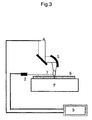
- Fig. 3 is a diagram illustrating one example of a method of setting the laser output variation condition according to the present invention.
- plasma or plume (1) is formed in a position to which a laser (4) is emitted due to an interaction between the laser (4) and a material to be welded (6) during laser welding.
- Emission of the plasma or the plume (1) is detected by a sensor composed of a photodiode (2) or the like provided near a welded portion, and this light emission is synchronized with a change in the laser (4) output so as to be recorded in a recording device (3).
- a sensor composed of a photodiode (2) or the like provided near a welded portion
- the laser (4) output variation condition is set so that the time change in the light emission strength of the plasma or the plume (1) is in response to the variation in the laser (4) output, the occurrence of the weld defects can be easily prevented during laser (4) welding.
- the time change in the light emission strength has periodicity which can be regarded to be approximately the same as the variation in the laser output, and further it is required that maximum peak time in each period of the light emission strength matches with or approximately matches with the time of a peak output of the laser.
- the light emission strength obtains a low value at each period at the time of a laser base output.
- the laser welding method which is provided by the present invention, data about the time change in the light emission strength of the plasma or the plume (1) obtained in the above manner are analyzed with frequency, and the level of a frequency component which is the same or close to the variation frequency of the laser output is obtained.
- the laser output variation condition is set so that the level becomes maximum.
- the peak of the amplitude in the frequency component which matches with the variation frequency is the largest when the frequency of the output variation is the optimum condition, and the peak becomes small when the frequency of the output variation is deviated from the optimum condition. This shows that the response between the variation in the plasma signal and the output variation is high or low.
- the peak at which the amplitude is large is observed in the frequency component which matches with the frequency (22.2 Hz) of the variation in the laser (4) output as shown in Fig. 5 .
- the output is varied at another variation frequency, for example 10 Hz, the peak is found in a position of 10 Hz, but its height is smaller than the case of the optimum frequency.
- Fig. 10 illustrates a result of obtaining the amplitude (peak value) in the frequency component which matches with the variation frequency under the respective output variation conditions.
- the frequency analyzing method is not particularly limited, and thus any analyzing methods which are used widely and generally can be used.
- the fast Fourier transforming method or the like can be used.
- an arbitrary threshold value is set to the time change in the light emission strength of the plasma or the plume (1) obtained in the above manner, and the laser (4) output variation condition is set so that the sum of time at which the light emission strength becomes the threshold value or less becomes minimum.
- the laser (4) output variation condition can be, therefore, set so that the break-off period of the plasma (1) emission signal, namely, the variation in the keyhole to the radial direction becomes minimum.
- Detection of the state in which the signal breaks off for short time can be made more simply by setting an arbitrary threshold value to the time change in the light emission strength and detecting the time at which the light emission strength becomes the threshold value or less.
- the threshold value of the light emission strength can be set arbitrarily according to a welding state or by a detecting unit for the light emission strength, but generally whether the state in which the break-off of the light emission for a while can be determined is included is used as guide of the setting of the threshold value.
- the time at which the light emission is disrupted can be set arbitrarily, and in the present invention, the laser output variation condition can be set so that the sum of the time at which the light emission strength is the threshold value or less for longer time than a predetermined time becomes minimum.
- the predetermined time varies according to various conditions in the detection of the light emission signal, but about 2 ms can be shown as a rough guide.
- the laser output variation condition can be set more simply without accurately detecting the disruption of the light emission. As a result, the variation of the keyhole to the radial direction is suppressed, and the stable keyhole is maintained, thereby realizing the condition that effectively prevents the formation of the porosity.
- the method according to the present invention can obtain the optimum laser output variation condition for a very short time on the moment at the time of the laser welding. This method can be used also as feedback control.
- a new laser welding method that can optimize the laser output variation condition more simply and securely is provided.
- thick materials can be welded easily with high quality, and thus this method is expected to contribute to practical application of laser welding of thick materials.
Landscapes
- Engineering & Computer Science (AREA)
- Physics & Mathematics (AREA)
- Optics & Photonics (AREA)
- Mechanical Engineering (AREA)
- Plasma & Fusion (AREA)
- Quality & Reliability (AREA)
- Laser Beam Processing (AREA)
Abstract
Claims (3)
- Procédé de soudage au laser, qui consiste à faire varier une forme d'onde et une fréquence d'une sortie laser d'une manière contrôlée, de façon à éviter l'apparition de défauts de soudure, et à détecter une variation dans le temps de l'intensité d'émission de lumière du plasma ou du panache généré par une partie soudée au laser, caractérisé par l'analyse des caractéristiques fréquentielles de l'émission de lumière pour obtenir une amplitude d'une composante fréquentielle qui est identique ou proche d'une fréquence de variation de la sortie laser, et l'établissement d'une condition de variation de sortie laser de sorte que l'amplitude de la composante fréquentielle devienne maximum.
- Procédé de soudage au laser selon la revendication 1, qui consiste, à l'étape de détection, à détecter la variation dans le temps de l'intensité d'émission de lumière du plasma ou du panache généré par la partie soudée au laser, à fixer en outre une valeur de seuil arbitraire pour la variation dans le temps de l'intensité d'émission de lumière du plasma ou du panache, et établir la condition de variation de la sortie laser de sorte que le temps total pour que l'intensité d'émission de lumière atteigne la valeur de seuil ou moins devienne minimum.
- Procédé de soudage au laser selon la revendication 2, qui consiste à établir la condition de variation de la sortie laser de sorte que le temps total pour que l'intensité d'émission de lumière atteigne la valeur de seuil ou moins pendant un temps plus long qu'un temps prédéterminé devienne minimum.
Applications Claiming Priority (2)
| Application Number | Priority Date | Filing Date | Title |
|---|---|---|---|
| JP2004055336A JP4688423B2 (ja) | 2004-02-27 | 2004-02-27 | レーザ溶接方法 |
| PCT/JP2005/003417 WO2005082568A1 (fr) | 2004-02-27 | 2005-02-23 | Procédé de soudage au laser |
Publications (3)
| Publication Number | Publication Date |
|---|---|
| EP1726397A1 EP1726397A1 (fr) | 2006-11-29 |
| EP1726397A4 EP1726397A4 (fr) | 2009-04-01 |
| EP1726397B1 true EP1726397B1 (fr) | 2011-10-26 |
Family
ID=34908861
Family Applications (1)
| Application Number | Title | Priority Date | Filing Date |
|---|---|---|---|
| EP05719733A Expired - Lifetime EP1726397B1 (fr) | 2004-02-27 | 2005-02-23 | Procede de soudage au laser |
Country Status (4)
| Country | Link |
|---|---|
| US (1) | US20070289955A1 (fr) |
| EP (1) | EP1726397B1 (fr) |
| JP (1) | JP4688423B2 (fr) |
| WO (1) | WO2005082568A1 (fr) |
Families Citing this family (11)
| Publication number | Priority date | Publication date | Assignee | Title |
|---|---|---|---|---|
| US8723078B2 (en) * | 2008-11-21 | 2014-05-13 | The Regents Of The University Of Michigan | Monitoring of a welding process |
| KR101182235B1 (ko) * | 2009-12-14 | 2012-09-12 | 삼성디스플레이 주식회사 | 증착용 마스크, 그의 제조 방법 및 제조 장치 |
| JP5878330B2 (ja) * | 2011-10-18 | 2016-03-08 | 株式会社ディスコ | レーザー光線の出力設定方法およびレーザー加工装置 |
| EP2730362A1 (fr) * | 2012-11-13 | 2014-05-14 | Siemens Aktiengesellschaft | Processus de rayonnement au plasma et un dispositif correspondant avec un détecteur de plasma |
| JP5947740B2 (ja) | 2013-03-29 | 2016-07-06 | トヨタ自動車株式会社 | 溶接部の検査装置とその検査方法 |
| DE102014117157B4 (de) * | 2014-11-24 | 2017-02-16 | Scansonic Mi Gmbh | Verfahren und Vorrichtung zum Fügen von Werkstücken an einem Überlappungsstoß |
| US20170165774A1 (en) * | 2015-12-09 | 2017-06-15 | Baziuk Holdings Ltd. | Vertical Upward Welding in Which Wire Feed is Interrupted |
| DE102016204578B3 (de) | 2016-03-18 | 2017-08-17 | Trumpf Laser- Und Systemtechnik Gmbh | Laserschweißen von Stahl mit Leistungsmodulation zur Heißrissvermeidung |
| DE102016204577B4 (de) * | 2016-03-18 | 2019-07-11 | Trumpf Laser- Und Systemtechnik Gmbh | Verfahren zur Bestimmung der Qualität einer Schweißnaht sowie dazugehörige Verfahren zur Optimierung und Regelung von Fertigungsparametern |
| DE102020110087A1 (de) * | 2020-04-09 | 2021-10-14 | Ii-Vi Delaware, Inc. | Verfahren zur prozesskontrolle bei der lasermaterialbearbeitung |
| DE102021110241A1 (de) | 2021-04-22 | 2022-10-27 | Audi Aktiengesellschaft | Verfahren zum Laserstrahlfügen |
Family Cites Families (12)
| Publication number | Priority date | Publication date | Assignee | Title |
|---|---|---|---|---|
| US4446354A (en) * | 1981-05-29 | 1984-05-01 | The United States Of America As Represented By The Secretary Of The Army | Optoelectronic weld evaluation system |
| JP2798218B2 (ja) | 1990-01-08 | 1998-09-17 | 三菱重工業株式会社 | レーザ溶接モニタリング装置 |
| DE4002627A1 (de) * | 1990-01-30 | 1991-08-08 | Deutsche Forsch Luft Raumfahrt | Schweissueberwachungseinrichtung |
| US5651903A (en) * | 1995-10-12 | 1997-07-29 | Trw Inc. | Method and apparatus for evaluating laser welding |
| JP3209097B2 (ja) * | 1996-06-18 | 2001-09-17 | 日産自動車株式会社 | レーザ溶接の品質検査方法およびその装置 |
| US5961859A (en) * | 1997-10-23 | 1999-10-05 | Trw Inc. | Method and apparatus for monitoring laser weld quality via plasma size measurements |
| JP4741087B2 (ja) * | 2001-02-01 | 2011-08-03 | 独立行政法人物質・材料研究機構 | レーザ溶接方法 |
| JP4873588B2 (ja) | 2001-03-16 | 2012-02-08 | 独立行政法人物質・材料研究機構 | レーザ溶接方法 |
| US6900410B2 (en) | 2001-02-01 | 2005-05-31 | National Institute For Materials Science | Laser welding processed |
| JP3603843B2 (ja) * | 2001-02-23 | 2004-12-22 | 日産自動車株式会社 | レーザー溶接部の品質モニタリング方法およびその装置 |
| JP2002257195A (ja) | 2001-02-27 | 2002-09-11 | Aisin Seiki Co Ltd | 捩れ振動緩衝装置 |
| JP4136551B2 (ja) * | 2002-09-02 | 2008-08-20 | 独立行政法人物質・材料研究機構 | レーザ溶接方法 |
-
2004
- 2004-02-27 JP JP2004055336A patent/JP4688423B2/ja not_active Expired - Fee Related
-
2005
- 2005-02-23 US US10/590,706 patent/US20070289955A1/en not_active Abandoned
- 2005-02-23 WO PCT/JP2005/003417 patent/WO2005082568A1/fr not_active Ceased
- 2005-02-23 EP EP05719733A patent/EP1726397B1/fr not_active Expired - Lifetime
Also Published As
| Publication number | Publication date |
|---|---|
| JP4688423B2 (ja) | 2011-05-25 |
| WO2005082568A1 (fr) | 2005-09-09 |
| US20070289955A1 (en) | 2007-12-20 |
| EP1726397A4 (fr) | 2009-04-01 |
| JP2005238323A (ja) | 2005-09-08 |
| EP1726397A1 (fr) | 2006-11-29 |
Similar Documents
| Publication | Publication Date | Title |
|---|---|---|
| EP1726397B1 (fr) | Procede de soudage au laser | |
| EP0454749B1 (fr) | Methode et appareil de soudure | |
| US7278315B1 (en) | Laser-ultrasonic detection of subsurface defects in processed metals | |
| JP6541778B2 (ja) | 溶接装置および溶接品質検査方法 | |
| US20120298870A1 (en) | Method for automated testing of a material joint | |
| JP4662621B2 (ja) | 高エネルギビームを用いて材料加工する方法及び装置 | |
| KR101912972B1 (ko) | 초음파 검사 장치 및 초음파 검사 방법 | |
| EP4124859B1 (fr) | Dispositif d'inspection de soudure, système de soudure et procédé d'inspection de soudure | |
| JP2006082222A (ja) | レーザーショック処理を監視するシステム及び方法 | |
| JP2008151763A (ja) | 溶接部測定方法及び溶接部測定装置 | |
| Oussaid et al. | Experimental investigation of laser welding process in overlap joint configuration | |
| JPH08281456A (ja) | レーザ溶接の貫通検知方法およびその装置 | |
| JP4927659B2 (ja) | レーザ溶接方法 | |
| EP4480629A2 (fr) | Procédé d'inspection de soudure pour inspecter une soudure | |
| JP4136547B2 (ja) | パルスレーザ溶接方法 | |
| US4859830A (en) | Method of determining the weldability of a part | |
| JP4136551B2 (ja) | レーザ溶接方法 | |
| JP2021090992A (ja) | レーザ貫通溶接モニタリングシステムおよびレーザ貫通溶接モニタリング方法 | |
| JP4667446B2 (ja) | パルスレーザ溶接におけるレーザ出力のパルス周波数の決定方法 | |
| JP2008068325A (ja) | レーザ溶接の出力変調波形の決定方法 | |
| JP3292008B2 (ja) | レーザ溶接におけるワークの溶融状態判定方法 | |
| JP2005300182A (ja) | レーザ加工装置 | |
| Kamimuki et al. | Development of monitoring method for YAG laser welding and its application. Study of monitoring technology for YAG laser welding | |
| US20250003927A1 (en) | Welding inspection device and welding inspection method | |
| Li | Weld integrity of tailor welded blanks |
Legal Events
| Date | Code | Title | Description |
|---|---|---|---|
| PUAI | Public reference made under article 153(3) epc to a published international application that has entered the european phase |
Free format text: ORIGINAL CODE: 0009012 |
|
| 17P | Request for examination filed |
Effective date: 20060914 |
|
| AK | Designated contracting states |
Kind code of ref document: A1 Designated state(s): DE FR |
|
| DAX | Request for extension of the european patent (deleted) | ||
| RBV | Designated contracting states (corrected) |
Designated state(s): DE FR |
|
| A4 | Supplementary search report drawn up and despatched |
Effective date: 20090303 |
|
| 17Q | First examination report despatched |
Effective date: 20090819 |
|
| GRAP | Despatch of communication of intention to grant a patent |
Free format text: ORIGINAL CODE: EPIDOSNIGR1 |
|
| GRAS | Grant fee paid |
Free format text: ORIGINAL CODE: EPIDOSNIGR3 |
|
| GRAA | (expected) grant |
Free format text: ORIGINAL CODE: 0009210 |
|
| AK | Designated contracting states |
Kind code of ref document: B1 Designated state(s): DE FR |
|
| REG | Reference to a national code |
Ref country code: DE Ref legal event code: R082 Ref document number: 602005030816 Country of ref document: DE Representative=s name: ABITZ & PARTNER, DE Ref country code: DE Ref legal event code: R082 Ref document number: 602005030816 Country of ref document: DE Representative=s name: ABITZ & PARTNER PATENTANWAELTE MBB, DE |
|
| REG | Reference to a national code |
Ref country code: DE Ref legal event code: R096 Ref document number: 602005030816 Country of ref document: DE Effective date: 20111222 |
|
| PLBE | No opposition filed within time limit |
Free format text: ORIGINAL CODE: 0009261 |
|
| STAA | Information on the status of an ep patent application or granted ep patent |
Free format text: STATUS: NO OPPOSITION FILED WITHIN TIME LIMIT |
|
| 26N | No opposition filed |
Effective date: 20120727 |
|
| REG | Reference to a national code |
Ref country code: DE Ref legal event code: R097 Ref document number: 602005030816 Country of ref document: DE Effective date: 20120727 |
|
| REG | Reference to a national code |
Ref country code: FR Ref legal event code: PLFP Year of fee payment: 11 |
|
| PGFP | Annual fee paid to national office [announced via postgrant information from national office to epo] |
Ref country code: DE Payment date: 20150219 Year of fee payment: 11 |
|
| PGFP | Annual fee paid to national office [announced via postgrant information from national office to epo] |
Ref country code: FR Payment date: 20150219 Year of fee payment: 11 |
|
| REG | Reference to a national code |
Ref country code: DE Ref legal event code: R119 Ref document number: 602005030816 Country of ref document: DE |
|
| REG | Reference to a national code |
Ref country code: FR Ref legal event code: ST Effective date: 20161028 |
|
| PG25 | Lapsed in a contracting state [announced via postgrant information from national office to epo] |
Ref country code: DE Free format text: LAPSE BECAUSE OF NON-PAYMENT OF DUE FEES Effective date: 20160901 Ref country code: FR Free format text: LAPSE BECAUSE OF NON-PAYMENT OF DUE FEES Effective date: 20160229 |