EP1726440B1 - Dispositif d'alimentation en encre - Google Patents
Dispositif d'alimentation en encre Download PDFInfo
- Publication number
- EP1726440B1 EP1726440B1 EP06252755A EP06252755A EP1726440B1 EP 1726440 B1 EP1726440 B1 EP 1726440B1 EP 06252755 A EP06252755 A EP 06252755A EP 06252755 A EP06252755 A EP 06252755A EP 1726440 B1 EP1726440 B1 EP 1726440B1
- Authority
- EP
- European Patent Office
- Prior art keywords
- ink
- ink cartridge
- supply path
- pump
- cartridge
- Prior art date
- Legal status (The legal status is an assumption and is not a legal conclusion. Google has not performed a legal analysis and makes no representation as to the accuracy of the status listed.)
- Not-in-force
Links
- 230000005499 meniscus Effects 0.000 claims abstract description 15
- 238000001514 detection method Methods 0.000 claims abstract description 5
- 238000007599 discharging Methods 0.000 claims abstract description 5
- 238000000034 method Methods 0.000 claims description 10
- 230000003028 elevating effect Effects 0.000 description 11
- 239000007788 liquid Substances 0.000 description 11
- 238000010926 purge Methods 0.000 description 4
- 230000008602 contraction Effects 0.000 description 2
- 238000005549 size reduction Methods 0.000 description 2
- 238000009825 accumulation Methods 0.000 description 1
- 230000000694 effects Effects 0.000 description 1
- 239000012530 fluid Substances 0.000 description 1
- 239000006260 foam Substances 0.000 description 1
- 230000005484 gravity Effects 0.000 description 1
- 208000024891 symptom Diseases 0.000 description 1
- 239000002699 waste material Substances 0.000 description 1
Images





Classifications
-
- B—PERFORMING OPERATIONS; TRANSPORTING
- B41—PRINTING; LINING MACHINES; TYPEWRITERS; STAMPS
- B41J—TYPEWRITERS; SELECTIVE PRINTING MECHANISMS, i.e. MECHANISMS PRINTING OTHERWISE THAN FROM A FORME; CORRECTION OF TYPOGRAPHICAL ERRORS
- B41J2/00—Typewriters or selective printing mechanisms characterised by the printing or marking process for which they are designed
- B41J2/005—Typewriters or selective printing mechanisms characterised by the printing or marking process for which they are designed characterised by bringing liquid or particles selectively into contact with a printing material
- B41J2/01—Ink jet
- B41J2/17—Ink jet characterised by ink handling
- B41J2/175—Ink supply systems ; Circuit parts therefor
- B41J2/17566—Ink level or ink residue control
-
- B—PERFORMING OPERATIONS; TRANSPORTING
- B41—PRINTING; LINING MACHINES; TYPEWRITERS; STAMPS
- B41J—TYPEWRITERS; SELECTIVE PRINTING MECHANISMS, i.e. MECHANISMS PRINTING OTHERWISE THAN FROM A FORME; CORRECTION OF TYPOGRAPHICAL ERRORS
- B41J2/00—Typewriters or selective printing mechanisms characterised by the printing or marking process for which they are designed
- B41J2/005—Typewriters or selective printing mechanisms characterised by the printing or marking process for which they are designed characterised by bringing liquid or particles selectively into contact with a printing material
- B41J2/01—Ink jet
- B41J2/17—Ink jet characterised by ink handling
- B41J2/175—Ink supply systems ; Circuit parts therefor
-
- B—PERFORMING OPERATIONS; TRANSPORTING
- B41—PRINTING; LINING MACHINES; TYPEWRITERS; STAMPS
- B41J—TYPEWRITERS; SELECTIVE PRINTING MECHANISMS, i.e. MECHANISMS PRINTING OTHERWISE THAN FROM A FORME; CORRECTION OF TYPOGRAPHICAL ERRORS
- B41J2/00—Typewriters or selective printing mechanisms characterised by the printing or marking process for which they are designed
- B41J2/005—Typewriters or selective printing mechanisms characterised by the printing or marking process for which they are designed characterised by bringing liquid or particles selectively into contact with a printing material
- B41J2/01—Ink jet
- B41J2/17—Ink jet characterised by ink handling
- B41J2/175—Ink supply systems ; Circuit parts therefor
- B41J2/17503—Ink cartridges
- B41J2/17506—Refilling of the cartridge
- B41J2/17509—Whilst mounted in the printer
-
- B—PERFORMING OPERATIONS; TRANSPORTING
- B41—PRINTING; LINING MACHINES; TYPEWRITERS; STAMPS
- B41J—TYPEWRITERS; SELECTIVE PRINTING MECHANISMS, i.e. MECHANISMS PRINTING OTHERWISE THAN FROM A FORME; CORRECTION OF TYPOGRAPHICAL ERRORS
- B41J2/00—Typewriters or selective printing mechanisms characterised by the printing or marking process for which they are designed
- B41J2/005—Typewriters or selective printing mechanisms characterised by the printing or marking process for which they are designed characterised by bringing liquid or particles selectively into contact with a printing material
- B41J2/01—Ink jet
- B41J2/17—Ink jet characterised by ink handling
- B41J2/19—Ink jet characterised by ink handling for removing air bubbles
Definitions
- the present invention relates to an ink supplying apparatus that supplies ink from a cartridge to a recording head for discharging the ink.
- an ink supplying apparatus that supplies ink in an exchangeable ink cartridge to a recording head and also warns a fact that the ink cartridge becomes empty
- an apparatus disclosed in Japanese Patent Application Laid Open No. 11-91121 (1999 ) is known.
- This apparatus is designed such that a sub-tank is placed in a supply path of the ink between the ink cartridge and the recording head, and the ink in the ink cartridge can be supplied to the sub-tank by using a pump.
- a liquid surface level sensor for detecting an ink liquid surface level is provided in the sub-tank.
- the pump is used to supply the ink from the ink cartridge to the sub-tank. Even if the pump is driven, if the ink liquid surface level detected by the liquid surface level sensor is the predetermined level or less, the ink cartridge is judged to be empty, and a warning for urging a user to exchange the ink cartridge is issued.
- US 4,380,770 discloses an ink jet printer which includes pumped-forced circulation of ink through the printer head and a nozzle cap in order to eliminate gas from the ink supply.
- ink from a tank circulates through the printer head and returns to the tank when the nozzles are capped. A brief flow of ink from the nozzles completes a purging of the head prior to printing.
- GB 2 326 378 discloses an ink cartridge with ink end detection electrode pins coupled to a circuit.
- a pump is started to suck a small amount of ink from the cartridge and extract any air bubbles from a supply port.
- the circuit measures the resistance between the electrode pins and compares it with a predetermined resistance in order to determine if all of the bubbles have been removed from the supply port.
- US 6,139,138 discloses a device for removing air or gas from an ink jet pen which includes a gas accumulation chamber attached to an ink cartridge and a gas inlet port in communication with a chamber, with the input port containing a symptom for receiving the port.
- the chamber contains an urging member to draw gas into the chamber through the inlet port from a cartridge body upon attachment of the cartridge to the body.
- US 4,476,472 discloses a combined ink cartridge/bubble removing device which is detachably secured to an ink liquid supply system for an ink jet printer.
- the device includes a housing having a bottom wall provided with an ink inlet portion and an ink outlet portion.
- the device also has an ink liquid tray which has an inlet opening connected to the ink inlet portion via a vertical pipe, and an outlet opening for dropping ink liquid within the housing. When ink travels upward in the vertical pipe, bubbles included in the ink are removed and discharged.
- the sub-tank is placed in the supply path between the ink cartridge and the recording head.
- the apparatus becomes complex, which results in a problem that the apparatus is large in size.
- An object of the present invention is to provide an ink supplying apparatus which is simple in configuration and small in size.
- an ink supplying apparatus comprising a supply path of ink to connect an exchangeable ink cartridge and a recording head for discharging ink, characterized by comprising:
- a supply pressure of the pump may be a pressure where a meniscus of the recording head is not broken.
- check valves for allowing the flow to the recording head side may be provided on both sides of the confluent portion in the supply path, and the check valve on the ink cartridge side may allow the back flow under the supply pressure.
- the pump may include a pump chamber whose capacity is variable, and the pump chamber may be able to store the ink which is equal to or greater than a capacity of the supply path between the ink cartridge and the confluent portion.
- the confluent portion is preferred to be arranged on the lower side than a nozzle surface of the recording head.
- the exhaustion control means drive-controls the pump to return the air in the supply path back to the ink cartridge and to suck and store the ink in the ink cartridge.
- the ink inside the supply path at the confluent portion or on the ink cartridge side with respect to the confluent portion can be detected by ink detecting means, and the detection result can be reported.
- the ink cartridge can be used until it becomes empty, and after the exchange of the ink cartridge, the ink is supplied from the pump to the supply path, and the air is returned back to the ink cartridge.
- the sub-tank is not required, which provides the effect that enables the simpler configuration and the size reduction.
- the ink is supplied under the pressure where the meniscus is not broken.
- the check valves are provided on both the sides of the confluent portion, and the check valve on the ink cartridge side allows the back flow under the supply pressure.
- the pump which can store the ink that is equal to or greater than the capacity of the supply path between the ink cartridge and the ink detecting means is provided, which enables the air flowing into the supply path to be surely returned back to the ink cartridge, and the configuration becomes simpler.
- the confluent portion is provided on the lower side than the nozzle surface. Then, even if the ink cartridge becomes empty, the back pressure can be stably applied to the recording head.
- the pump after the exhaustion of the air, the pump sucks and stores the ink in the ink cartridge.
- the pump having the simple configuration where the bellows and the like are used can be used.
- an exchangeable ink cartridge 1 and a recording head 2 are connected through a supply path 4 of ink.
- the recording head 2 is the ink jet type, which drives a piezoelectric element, a thermally converting element and the like and discharges the ink supplied through the supply path 4 to a manifold 6 from a nozzle 8 (refer to FIG.2 ) as an ink drop.
- a pump 12 is connected at a confluent portion 10 in the course of the supply path 4 between the ink cartridge 1 and the recording head 2.
- the pump 12 is not directly connected to the ink cartridge 1, and it is connected at the confluent portion 10 in the course of the supply path 4.
- the supply path 4 from the confluent portion 10 to the ink cartridge 1 is located on the lower side in a gravity direction than a nozzle surface 2a of the recording head 2. Consequently, in such a way that a negative pressure can be applied, even if the ink cartridge 1 becomes empty which will be described later, a back pressure can be stably applied to the recording head 2.
- a bellows pump As the pump 12, in this embodiment, a bellows pump is used.
- a pump chamber 16 constituted by a bellows 14 is linked to the confluent portion 10.
- the bellows 14 is designed so as to be expanded or contracted, and the expansion/contraction of the bellows 14 is configured so as to change the capacity of the pump chamber 16.
- the pump 12 is not limited to the bellows 14.
- a bellows, a balloon and the like which have the expansion/contraction performance may be used.
- the bellows 14 is provided on an elevating bar 18, and both ends of the elevating bar 18 are rotatably supported on sides of the rotation plates 20, 22, respectively. Both ends of a linkage bar 19 are rotatably supported on the sides of the rotation plates 20, 22 at a position symmetrical with the elevating bar 18. Then, when both of the rotation plates 20, 22 are rotated in the same direction, the elevating bar 18 is configured so as to be elevated.
- the elevating bar 18 is raised from the lowest position indicated by a solid line in FIG. 1 to the highest position. Moreover, when the rotation plates 20, 22 are rotated by 180 degrees, they are returned back to the original lowest position shown by the solid line.
- the elevating bar 18 is raised from the low position to the high position, the bellows 14 is contracted to consequently change the capacity of the pump chamber 16.
- the pump chamber 16 is at least formed so as to store the ink which is equal to or greater than the capacity of the supply path 4 between the ink cartridge 1 and the portion (the confluent portion 10, in this embodiment) where an ink detecting sensor 42 (ink detecting means) is provided. Then, this is designed so as to discharge the ink which is equal to or greater than the capacity of the supply path 4 between the ink cartridge 1 and the portion where the ink detecting sensor 42 is provided, while the elevating bar 18 is raised from the lowest position to the highest position.
- This apparatus is designed such that a rotation of a driving source 24, such as a motor or the like, is transmitted through a gear mechanism 26 to one rotation plate 20.
- the driving source 24 may be configured such that it is shared as a driving source for rotating a platen or the like (not shown) to send a recording medium such as a paper and the like and such that they are switched by the gear mechanism 26.
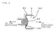
- check valves 28, 30 are placed on both sides of the confluent portion 10 with the confluent portion 10 therebetween, respectively. Both of the check valves 28, 30 are placed so as to allow the ink to flow to the recording head 2 from the ink cartridge 1. Also, the check valve 30 between the ink cartridge 1 and the confluent portion 10 includes a flexible valve body 32 having a shape of an umbrella, as shown in FIG. 3 and is seated on a valve seat 34 formed in the course of the supply path 4 and regulates the flow of the ink to the side of the ink cartridge 1 from the confluent portion 10.
- a protrusion 36 is formed on the valve seat 34 and the check valve 30 is configured such that and such that a part of the valve body 32 is brought into contact with the protrusion 36.
- the ink pressure of the confluent portion 10 side is the pressure where a meniscus 40 generated in the nozzle 8 is not broken, a gap is formed between the valve body 32 and the valve seat 34 in the vicinity of the protrusion 36, and the ink flows to the ink cartridge 1 side from the confluent portion 10 side.
- the ink detecting sensor 42 is provided in the confluent portion 10.
- the ink detecting sensor 42 may be provided in the supply path 4 between the confluent portion 10 and the ink cartridge 1.
- the ink detecting sensor 42 detects the presence or absence of the ink in the supply path 4 at the portion where the ink detecting sensor 42 is provided, and it may be a photo type, an electric resistance type or the like.
- the ink detecting sensor 42 and the driving source 24 are connected to a control circuit 44 (a controller) and includes a CPU which controls the driving source 24 and the like in accordance with a control program with regard to an operation content, a ROM, a RAM and the like.
- a display section 46 is connected to the control circuit 44, and the display section 46 includes a light emitting diode, which is flashed when the ink cartridge is empty, and the like.
- the recording head 2 is driven in accordance with an image data, and the ink in the manifold 6 is discharged as the ink drop from the nozzle 8 to the recording medium such as a paper and the like, and the pattern of an ink dot is recorded.
- the consumed ink is supplemented from the ink cartridge 1 through the supply path 4 and the check valves 28, 30 to the manifold 6. With the consumption of the ink, the ink in the ink cartridge 1 is reduced, thereby lowering an ink liquid surface level inside the ink cartridge 1.
- Step 100 whether or not the ink cartridge is empty is judged. Whether or not the ink cartridge is empty is judged in accordance with the result of the presence or absence of the ink detected by the ink detecting sensor 42.
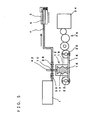
- Step 100 If there is the ink (Step 100: No), it waits in an original state, and the recording through the recording head 2 is continued. Then, when the ink in the ink cartridge 1 is consumed, as shown in FIG.5 , the ink cartridge 1 becomes empty. The ink still remains in the supply path 4 between the ink cartridge 1 and the ink detecting sensor 42. Moreover, the recording to the recording medium is continued.
- Step 110 the light emitting diode in the display section 46 is flashed, or the alarm signal is transmitted to an external apparatus such as a personal computer and the like. Then, the fact that the ink cartridge 1 becomes empty and must be exchanged is reported to the user.
- Step 120 whether or not the ink cartridge 1 is exchanged is judged (Step 120), and it waits until the exchange is carried out (Step 120: No).
- Step 120: Yes when it is exchanged with a new ink cartridge 1 (Step 120: Yes), the pump 12 is driven (Step 130).
- air 48 remains between the ink cartridge 1 and the confluent portion 10 where the ink detecting sensor 42 is provided.
- whether or not the ink cartridge 1 is exchanged may be judged, for example, in accordance with a detection signal or the like by detecting a fact that a cover (not shown) or the like is opened and closed when the ink cartridge 1 is exchanged.
- the control circuit 44 controls the rotation number of the driving source 24, and the rotation plate 20 is rotated through the gear mechanism 26. Consequently, the elevating bar 18 is raised to contract the bellows 14. Then, the ink is supplied from the bellows 14 through the confluent portion 10 to the supply path 4.
- the rotation number of the driving source 24 is controlled such that the ink pressure discharged from the bellows 14 becomes the pressure under which the meniscus 40 in the nozzle 8 is not broken, for example, the pressure of about 4 kPa. Consequently, under the pressure where the meniscus 40 is not broken, the ink is supplied through the confluent portion 10 to the supply path 4.
- the meniscus 40 is generated in the nozzle 8 in the recording head 2.
- the ink is supplied under the pressure where the meniscus 40 is broken, the ink is discharged from the nozzle 8.
- the ink pressure discharged from the pump 12 is set to the pressure where the meniscus 40 is not broken, the ink flows from the confluent portion 10 through the supply path 4 to the side of the ink cartridge 1, and it does not flow from the confluent portion 10 to the supply path 4 on the side of the recording head 2.
- an electromagnetic opening/closing valve may be placed in the supply path 4 between the confluent portion 10 and the recording head 2, and when the pump 12 is driven, the electromagnetic opening/closing valve may be closed. At that time, the ink pressure discharged from the pump 12 may be equal to or greater than the pressure where the meniscus 40 is broken. By setting the ink pressure discharged from the pump 12 to the pressure where the meniscus 40 is not broken, it is possible to return the air 48 back to the ink cartridge 1 without providing the electromagnetic opening/closing valve. Thus, the structure becomes simpler.
- the ink flows from the confluent portion 10 into the supply path 4 on the side of the ink cartridge 1 and pushes the air 48, which remains in the supply path 4, toward the ink cartridge 1.
- the check valve 30 allows the flow to the side of the ink cartridge 1.
- the air 48 and the ink flow through the check valve 30 into the ink cartridge 1.
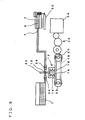
- the air 48 flowing into the ink cartridge 1 is changed into air bubble and raised as shown in FIG.7 and sent out from the ink cartridge 1 to atmosphere.
- the ink cartridge 1 can be used until the ink cartridge 1 becomes perfectly empty, and the air 48 inside the supply path 4 is exhausted into the ink cartridge 1 by driving the pump 12.
- the ink cartridge 1 can be exchanged without uselessly discarding the ink.
- the sub-tank and the like are not required to be provided, which enables the simpler structure and the size reduction.
- the pump 12 discharges the ink, which is equal to or greater than the capacity of the supply path 4 between the ink cartridge 1 and the portion where the ink detecting sensor 42 is provided.
- the configuration is simple. That is, the bellows 14 is used to discharge the necessary quantity of the ink, while the elevating bar 18 is raised from the lowest position to the highest position. Hence, the configuration of the pump 12 becomes simple.
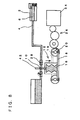
- the pump 12 is driven to raise the elevating bar 18 to the highest position, as shown in FIG.7 , and it waits for the elapse of the predetermined period (Step 140), and the sucking operation is carried out by the pump 12 (Step 150).
- the sucking operation by the pump 12 as shown in FIG.8 , the driving source 24 is controlled to transmit the rotation of the driving source 24 through the gear mechanism 26 to the rotation plate 20.
- the elevating bar 18 is moved from the highest position to the lowest position, and the bellows 14 is meanwhile expanded to increase the capacity.
- the ink is sucked from the ink cartridge 1 through the supply path 4 and the check valve 30 into the pump chamber 16 of the bellows 14, and the pump chamber 16 is filled with the ink.
- the pump 12 of the simple configuration using the bellows 14 can be used.
- the execution of the processes at the steps 100, 110 acts as the reporting means.
- the execution of the processes at the steps 120 to 140 acts as the exhaustion control means.
- pursing means for carrying out a purging operation is also shared by driving the pump 12. That is, the pump 12 is driven to contract the bellows 14, and the ink is supplied from the pump chamber 16 through the confluent portion 10 to the supply path 4 and supplied through the check valve 28 to the recording head 2. Consequently, the ink can be discharged from the nozzle 8 and sucked into a waste fluid foam 50.
- the check valve 30 prevents the ink from flowing back to the ink cartridge 1.
- the dry ink and the like can be suitably exhausted, thereby protecting the nozzle 8 from being clogged. Since the check valves 28, 30 are provided on both the sides of the confluent portion 10, the purging operation can be shared.
Landscapes
- Ink Jet (AREA)
- Dot-Matrix Printers And Others (AREA)
- Coating Apparatus (AREA)
Claims (10)
- Appareil d'alimentation en encre comportant un trajet d'alimentation (4) en encre permettant de raccorder une cartouche d'encre échangeable (1) et une tête d'enregistrement (2) pour décharger l'encre, caractérisé en ce qu'il comprend :une pompe (12) contenant une chambre capable de stocker l'encre et qui peut aspirer et stocker l'encre de la cartouche d'encre (1) dans la chambre et introduire l'encre stockée dans la chambre dans ledit trajet d'alimentation (4) par une portion confluente (10) dudit trajet d'alimentation (4) et de la pompe (12) ; etun moyen de commande d'évacuation pour :juger si ladite cartouche d'encre (1) est échangée ou non ; ets'il juge que ladite cartouche d'encre (1) a été échangée, commander ladite pompe (12) pour introduire ladite encre stockée dans la chambre, avant un échange de ladite cartouche d'encre (1), dans ledit trajet d'encre (4) sur ladite face de la cartouche d'encre (1) par rapport à ladite portion confluente (10) et renvoyer l'air présent dans ledit trajet d'alimentation (4) sur ladite face de la cartouche d'encre (1) par rapport à ladite portion confluente (10) jusque dans ladite cartouche d'encre (1).
- Appareil d'alimentation en encre selon la revendication 1, dans lequel une pression d'alimentation de ladite pompe (12) est une pression telle qu'un ménisque de ladite tête d'enregistrement (2) n'est pas rompu.
- Appareil d'alimentation en encre selon la revendication 2 comprenant en outre des clapets anti-retour (28, 30) qui sont installés des deux côtés de ladite portion confluente (10) dudit trajet d'alimentation (4) et qui permettent un écoulement jusqu'à ladite face de la tête d'enregistrement (2), dans lequel ledit clapet anti-retour (30) sur ladite face de la cartouche d'encre (1) permet un retour de fluide sous l'effet de ladite pression d'alimentation.
- Appareil d'alimentation en encre selon l'une quelconque des revendications 1 à 3, dans lequel ladite chambre est une chambre d'aspiration (16) dont la capacité est variable, et la chambre d'aspiration (16) peut stocker ladite encre qui est égale ou supérieure à une capacité dudit trajet d'alimentation (4) entre ladite cartouche d'encre (1) et ladite portion confluente (10).
- Appareil d'alimentation en encre selon l'une quelconque des revendications 1 à 4, dans lequel ladite portion confluente (10) est aménagée sur un côté inférieur à une surface de buses (2a) de ladite tête d'enregistrement (2).
- Appareil d'alimentation en encre selon l'une quelconque des revendications 1 à 5, dans lequel ledit moyen de commande d'évacuation commande ladite pompe (12) pour renvoyer l'air présent dans ledit trajet d'alimentation (4) jusque dans ladite cartouche d'encre (1) et ensuite, pour aspirer et stocker ladite encre dans ladite cartouche d'encre (1).
- Appareil d'alimentation en encre selon l'une quelconque des revendications 1 à 6 comprenant en outre :un moyen de détection d'encre (42) permettant de détecter ladite encre dans ledit trajet d'alimentation (4) au niveau de ladite portion confluente (10) ou sur la face de ladite cartouche d'encre (1) par rapport à ladite portion confluente (10) ; etun moyen d'indication pour, lorsque le moyen de détection d'encre (42) détecte qu'il n'y a pas d'encre, indiquer le résultat de la détection.
- Procédé d'alimentation en encre d'un appareil d'alimentation en encre comportant un trajet d'alimentation (4) en encre permettant de raccorder une cartouche d'encre échangeable (1) et une tête d'enregistrement (2) pour décharger l'encre, et une pompe (12) contenant une chambre capable de stocker l'encre, et qui peut aspirer et stocker l'encre de la cartouche d'encre (1) dans la chambre et introduire l'encre stockée dans la chambre dans ledit trajet d'alimentation (4) par une portion confluente (10) dudit trajet d'alimentation (4) et de la pompe (12) ; caractérisé en ce qu'il comprend :une étape de commande de ladite pompe (12) pour aspirer et stocker l'encre de la cartouche d'encre (1) dans la chambre ;une étape pour juger si ladite cartouche d'encre (1) est échangée ou non ; etune étape d'évacuation de l'air, lorsque l'on juge que ladite cartouche d'encre (1) a été échangée, permettant de commander ladite pompe (12) pour introduire ladite encre stockée dans la chambre, avant un échange de ladite cartouche d'encre (1), dans ledit trajet d'encre (4) sur ladite face de la cartouche d'encre (1) par rapport à ladite portion confluente (10) et de renvoyer l'air présent dans ledit trajet d'alimentation (4) sur ladite face de la cartouche d'encre (1) par rapport à ladite portion confluente (10) jusque dans ladite cartouche d'encre (1).
- Procédé d'alimentation en encre selon la revendication 8, dans lequel ladite pompe (12) alimente l'encre sous une pression telle qu'un ménisque de ladite tête d'enregistrement (2) n'est pas rompu.
- Procédé d'alimentation en encre selon l'une quelconque des revendications 8 à 9, comprenant en outre une étape d'aspiration et de stockage de ladite encre dans ladite cartouche d'encre (1) après l'étape d'évacuation de l'air.
Applications Claiming Priority (1)
| Application Number | Priority Date | Filing Date | Title |
|---|---|---|---|
| JP2005156043 | 2005-05-27 |
Publications (2)
| Publication Number | Publication Date |
|---|---|
| EP1726440A1 EP1726440A1 (fr) | 2006-11-29 |
| EP1726440B1 true EP1726440B1 (fr) | 2008-07-23 |
Family
ID=36754115
Family Applications (1)
| Application Number | Title | Priority Date | Filing Date |
|---|---|---|---|
| EP06252755A Not-in-force EP1726440B1 (fr) | 2005-05-27 | 2006-05-26 | Dispositif d'alimentation en encre |
Country Status (4)
| Country | Link |
|---|---|
| US (1) | US7597430B2 (fr) |
| EP (1) | EP1726440B1 (fr) |
| AT (1) | ATE402019T1 (fr) |
| DE (1) | DE602006001896D1 (fr) |
Families Citing this family (10)
| Publication number | Priority date | Publication date | Assignee | Title |
|---|---|---|---|---|
| US20090153629A1 (en) * | 2007-12-18 | 2009-06-18 | Seiko Epson Corporation | Liquid supplying device and liquid ejecting apparatus |
| JP5045682B2 (ja) * | 2009-01-19 | 2012-10-10 | ブラザー工業株式会社 | インクジェットプリンタ |
| US8348406B2 (en) | 2010-07-30 | 2013-01-08 | Xerox Corporation | Liquid ink delivery system including a flow restrictor that resists air bubble formation in a liquid ink reservoir |
| US8506061B2 (en) | 2010-08-23 | 2013-08-13 | Xerox Corporation | Method and apparatus for purging and supplying ink to an inkjet printing apparatus |
| US8550612B2 (en) | 2010-10-20 | 2013-10-08 | Xerox Corporation | Method and system for ink delivery and purged ink recovery in an inkjet printer |
| US8403457B2 (en) | 2011-02-04 | 2013-03-26 | Xerox Corporation | Waste ink reclamation apparatus for liquid ink recirculation system |
| JP5887822B2 (ja) * | 2011-10-18 | 2016-03-16 | セイコーエプソン株式会社 | 液体供給装置及び液体噴射装置 |
| US8662649B2 (en) | 2012-01-18 | 2014-03-04 | Xerox Corporation | Method and system for printing recycled ink with process black neutralization |
| US8840230B2 (en) | 2012-06-04 | 2014-09-23 | Xerox Corporation | Ink waste tray configured with one way filter |
| JP6471844B2 (ja) * | 2013-12-10 | 2019-02-20 | 株式会社リコー | 画像形成装置 |
Family Cites Families (10)
| Publication number | Priority date | Publication date | Assignee | Title |
|---|---|---|---|---|
| JPS5675867A (en) * | 1979-11-22 | 1981-06-23 | Seiko Epson Corp | Ink jet recorder |
| JPS5924676A (ja) * | 1982-07-31 | 1984-02-08 | Sharp Corp | インクジェットプリンタの気泡除去装置 |
| US4896172A (en) * | 1987-11-20 | 1990-01-23 | Canon Kabushiki Kaisha | Liquid injection recording apparatus including recording liquid circulation control |
| US6322207B1 (en) * | 1995-04-27 | 2001-11-27 | Hewlett-Packard Company | Replaceable pump module for receiving replaceable ink supplies to provide ink to an ink jet printing system |
| US6196668B1 (en) * | 1997-05-12 | 2001-03-06 | Marconi Data Systems | Ink jet print head modules with common ink supply |
| GB2326378B (en) * | 1996-06-25 | 1999-06-09 | Seiko Epson Corp | Ink cartridge,ink cartridge mounting device and detection plates of ink end detector |
| JPH1191121A (ja) | 1997-09-18 | 1999-04-06 | Canon Aptex Inc | 液体残量検知方法およびその装置 |
| US6139138A (en) * | 1999-04-13 | 2000-10-31 | Lexmark International, Inc. | Bellows system for an ink jet pen |
| JP4064739B2 (ja) * | 2002-06-24 | 2008-03-19 | 東芝テック株式会社 | インクジェットヘッドのメンテナンス方法及びメンテナンス装置 |
| JP2005067122A (ja) * | 2003-08-27 | 2005-03-17 | Fuji Photo Film Co Ltd | インクジェット記録装置 |
-
2006
- 2006-05-26 DE DE602006001896T patent/DE602006001896D1/de active Active
- 2006-05-26 AT AT06252755T patent/ATE402019T1/de not_active IP Right Cessation
- 2006-05-26 US US11/420,691 patent/US7597430B2/en active Active
- 2006-05-26 EP EP06252755A patent/EP1726440B1/fr not_active Not-in-force
Also Published As
| Publication number | Publication date |
|---|---|
| US7597430B2 (en) | 2009-10-06 |
| EP1726440A1 (fr) | 2006-11-29 |
| DE602006001896D1 (de) | 2008-09-04 |
| US20060268042A1 (en) | 2006-11-30 |
| ATE402019T1 (de) | 2008-08-15 |
Similar Documents
| Publication | Publication Date | Title |
|---|---|---|
| JP4720876B2 (ja) | インクジェット記録装置 | |
| KR101430934B1 (ko) | 잉크젯 화상형성장치와 잉크 유동 제어방법 | |
| US7874656B2 (en) | Ink-feeding device and pressure-generating method | |
| EP1997639B1 (fr) | Appareil d'éjection de gouttelettes liquides | |
| JP5555505B2 (ja) | インクジェットプリンタ | |
| JP4433760B2 (ja) | 液体吐出装置 | |
| JP5899613B2 (ja) | 液体吐出ヘッドへの液体供給方法、液体供給機構、ならびに液体吐出装置 | |
| US20100079559A1 (en) | Fluid Circulation System | |
| US20100194798A1 (en) | Inkjet printer and ink circulation method thereof | |
| JP2015044379A (ja) | 液体吐出装置とその制御方法 | |
| EP1726440B1 (fr) | Dispositif d'alimentation en encre | |
| JP2010030205A (ja) | 液体供給装置、液体吐出装置、及び液体吐出装置の制御方法 | |
| JP5276902B2 (ja) | インクジェットプリンタ及びそのインク検出方法 | |
| JP6214356B2 (ja) | 撹拌装置、液体吐出装置、撹拌方法、インクジェット記録装置、およびインクジェット記録装置の制御方法 | |
| US11235577B2 (en) | Inkjet printer | |
| JP7764260B2 (ja) | 液体循環装置及び液体吐出装置 | |
| JP4534245B2 (ja) | インクジェット印刷装置 | |
| JP4782602B2 (ja) | インクジェット記録装置及びインクジェット記録方法 | |
| JP4830628B2 (ja) | インク供給装置 | |
| JP7388248B2 (ja) | インクジェットプリンタ、及びインクジェットプリンタにおけるインク供給方法 | |
| JP4944566B2 (ja) | インクジェット記録装置 | |
| JP4492171B2 (ja) | 液体噴射装置及び液体噴射装置のクリーニング方法 | |
| JP2005212184A (ja) | インクジェット記録装置 | |
| JP2011143614A (ja) | 画像形成装置 | |
| JP2004330484A (ja) | インク供給装置、およびインクジェット記録装置 |
Legal Events
| Date | Code | Title | Description |
|---|---|---|---|
| PUAI | Public reference made under article 153(3) epc to a published international application that has entered the european phase |
Free format text: ORIGINAL CODE: 0009012 |
|
| AK | Designated contracting states |
Kind code of ref document: A1 Designated state(s): AT BE BG CH CY CZ DE DK EE ES FI FR GB GR HU IE IS IT LI LT LU LV MC NL PL PT RO SE SI SK TR |
|
| AX | Request for extension of the european patent |
Extension state: AL BA HR MK YU |
|
| 17P | Request for examination filed |
Effective date: 20070502 |
|
| AKX | Designation fees paid |
Designated state(s): AT BE BG CH CY CZ DE DK EE ES FI FR GB GR HU IE IS IT LI LT LU LV MC NL PL PT RO SE SI SK TR |
|
| GRAP | Despatch of communication of intention to grant a patent |
Free format text: ORIGINAL CODE: EPIDOSNIGR1 |
|
| GRAS | Grant fee paid |
Free format text: ORIGINAL CODE: EPIDOSNIGR3 |
|
| GRAA | (expected) grant |
Free format text: ORIGINAL CODE: 0009210 |
|
| AK | Designated contracting states |
Kind code of ref document: B1 Designated state(s): AT BE BG CH CY CZ DE DK EE ES FI FR GB GR HU IE IS IT LI LT LU LV MC NL PL PT RO SE SI SK TR |
|
| REG | Reference to a national code |
Ref country code: GB Ref legal event code: FG4D |
|
| REG | Reference to a national code |
Ref country code: CH Ref legal event code: EP |
|
| REG | Reference to a national code |
Ref country code: IE Ref legal event code: FG4D |
|
| REF | Corresponds to: |
Ref document number: 602006001896 Country of ref document: DE Date of ref document: 20080904 Kind code of ref document: P |
|
| NLV1 | Nl: lapsed or annulled due to failure to fulfill the requirements of art. 29p and 29m of the patents act | ||
| PG25 | Lapsed in a contracting state [announced via postgrant information from national office to epo] |
Ref country code: IS Free format text: LAPSE BECAUSE OF FAILURE TO SUBMIT A TRANSLATION OF THE DESCRIPTION OR TO PAY THE FEE WITHIN THE PRESCRIBED TIME-LIMIT Effective date: 20081123 Ref country code: LT Free format text: LAPSE BECAUSE OF FAILURE TO SUBMIT A TRANSLATION OF THE DESCRIPTION OR TO PAY THE FEE WITHIN THE PRESCRIBED TIME-LIMIT Effective date: 20080723 Ref country code: NL Free format text: LAPSE BECAUSE OF FAILURE TO SUBMIT A TRANSLATION OF THE DESCRIPTION OR TO PAY THE FEE WITHIN THE PRESCRIBED TIME-LIMIT Effective date: 20080723 |
|
| PG25 | Lapsed in a contracting state [announced via postgrant information from national office to epo] |
Ref country code: PT Free format text: LAPSE BECAUSE OF FAILURE TO SUBMIT A TRANSLATION OF THE DESCRIPTION OR TO PAY THE FEE WITHIN THE PRESCRIBED TIME-LIMIT Effective date: 20081223 Ref country code: ES Free format text: LAPSE BECAUSE OF FAILURE TO SUBMIT A TRANSLATION OF THE DESCRIPTION OR TO PAY THE FEE WITHIN THE PRESCRIBED TIME-LIMIT Effective date: 20081103 Ref country code: SI Free format text: LAPSE BECAUSE OF FAILURE TO SUBMIT A TRANSLATION OF THE DESCRIPTION OR TO PAY THE FEE WITHIN THE PRESCRIBED TIME-LIMIT Effective date: 20080723 Ref country code: FI Free format text: LAPSE BECAUSE OF FAILURE TO SUBMIT A TRANSLATION OF THE DESCRIPTION OR TO PAY THE FEE WITHIN THE PRESCRIBED TIME-LIMIT Effective date: 20080723 Ref country code: AT Free format text: LAPSE BECAUSE OF FAILURE TO SUBMIT A TRANSLATION OF THE DESCRIPTION OR TO PAY THE FEE WITHIN THE PRESCRIBED TIME-LIMIT Effective date: 20080723 Ref country code: BG Free format text: LAPSE BECAUSE OF FAILURE TO SUBMIT A TRANSLATION OF THE DESCRIPTION OR TO PAY THE FEE WITHIN THE PRESCRIBED TIME-LIMIT Effective date: 20081023 Ref country code: LV Free format text: LAPSE BECAUSE OF FAILURE TO SUBMIT A TRANSLATION OF THE DESCRIPTION OR TO PAY THE FEE WITHIN THE PRESCRIBED TIME-LIMIT Effective date: 20080723 |
|
| PG25 | Lapsed in a contracting state [announced via postgrant information from national office to epo] |
Ref country code: BE Free format text: LAPSE BECAUSE OF FAILURE TO SUBMIT A TRANSLATION OF THE DESCRIPTION OR TO PAY THE FEE WITHIN THE PRESCRIBED TIME-LIMIT Effective date: 20080723 |
|
| PG25 | Lapsed in a contracting state [announced via postgrant information from national office to epo] |
Ref country code: EE Free format text: LAPSE BECAUSE OF FAILURE TO SUBMIT A TRANSLATION OF THE DESCRIPTION OR TO PAY THE FEE WITHIN THE PRESCRIBED TIME-LIMIT Effective date: 20080723 Ref country code: DK Free format text: LAPSE BECAUSE OF FAILURE TO SUBMIT A TRANSLATION OF THE DESCRIPTION OR TO PAY THE FEE WITHIN THE PRESCRIBED TIME-LIMIT Effective date: 20080723 |
|
| PG25 | Lapsed in a contracting state [announced via postgrant information from national office to epo] |
Ref country code: SK Free format text: LAPSE BECAUSE OF FAILURE TO SUBMIT A TRANSLATION OF THE DESCRIPTION OR TO PAY THE FEE WITHIN THE PRESCRIBED TIME-LIMIT Effective date: 20080723 Ref country code: RO Free format text: LAPSE BECAUSE OF FAILURE TO SUBMIT A TRANSLATION OF THE DESCRIPTION OR TO PAY THE FEE WITHIN THE PRESCRIBED TIME-LIMIT Effective date: 20080723 Ref country code: CZ Free format text: LAPSE BECAUSE OF FAILURE TO SUBMIT A TRANSLATION OF THE DESCRIPTION OR TO PAY THE FEE WITHIN THE PRESCRIBED TIME-LIMIT Effective date: 20080723 |
|
| PLBE | No opposition filed within time limit |
Free format text: ORIGINAL CODE: 0009261 |
|
| STAA | Information on the status of an ep patent application or granted ep patent |
Free format text: STATUS: NO OPPOSITION FILED WITHIN TIME LIMIT |
|
| 26N | No opposition filed |
Effective date: 20090424 |
|
| PG25 | Lapsed in a contracting state [announced via postgrant information from national office to epo] |
Ref country code: IT Free format text: LAPSE BECAUSE OF FAILURE TO SUBMIT A TRANSLATION OF THE DESCRIPTION OR TO PAY THE FEE WITHIN THE PRESCRIBED TIME-LIMIT Effective date: 20080723 |
|
| PG25 | Lapsed in a contracting state [announced via postgrant information from national office to epo] |
Ref country code: MC Free format text: LAPSE BECAUSE OF NON-PAYMENT OF DUE FEES Effective date: 20090531 |
|
| PG25 | Lapsed in a contracting state [announced via postgrant information from national office to epo] |
Ref country code: SE Free format text: LAPSE BECAUSE OF FAILURE TO SUBMIT A TRANSLATION OF THE DESCRIPTION OR TO PAY THE FEE WITHIN THE PRESCRIBED TIME-LIMIT Effective date: 20081023 |
|
| REG | Reference to a national code |
Ref country code: IE Ref legal event code: MM4A |
|
| PG25 | Lapsed in a contracting state [announced via postgrant information from national office to epo] |
Ref country code: IE Free format text: LAPSE BECAUSE OF NON-PAYMENT OF DUE FEES Effective date: 20090526 |
|
| PG25 | Lapsed in a contracting state [announced via postgrant information from national office to epo] |
Ref country code: PL Free format text: LAPSE BECAUSE OF FAILURE TO SUBMIT A TRANSLATION OF THE DESCRIPTION OR TO PAY THE FEE WITHIN THE PRESCRIBED TIME-LIMIT Effective date: 20080723 |
|
| PG25 | Lapsed in a contracting state [announced via postgrant information from national office to epo] |
Ref country code: GR Free format text: LAPSE BECAUSE OF FAILURE TO SUBMIT A TRANSLATION OF THE DESCRIPTION OR TO PAY THE FEE WITHIN THE PRESCRIBED TIME-LIMIT Effective date: 20081024 |
|
| REG | Reference to a national code |
Ref country code: CH Ref legal event code: PL |
|
| PG25 | Lapsed in a contracting state [announced via postgrant information from national office to epo] |
Ref country code: LI Free format text: LAPSE BECAUSE OF NON-PAYMENT OF DUE FEES Effective date: 20100531 Ref country code: CH Free format text: LAPSE BECAUSE OF NON-PAYMENT OF DUE FEES Effective date: 20100531 |
|
| PG25 | Lapsed in a contracting state [announced via postgrant information from national office to epo] |
Ref country code: LU Free format text: LAPSE BECAUSE OF NON-PAYMENT OF DUE FEES Effective date: 20090526 |
|
| PG25 | Lapsed in a contracting state [announced via postgrant information from national office to epo] |
Ref country code: HU Free format text: LAPSE BECAUSE OF FAILURE TO SUBMIT A TRANSLATION OF THE DESCRIPTION OR TO PAY THE FEE WITHIN THE PRESCRIBED TIME-LIMIT Effective date: 20090124 |
|
| PG25 | Lapsed in a contracting state [announced via postgrant information from national office to epo] |
Ref country code: TR Free format text: LAPSE BECAUSE OF FAILURE TO SUBMIT A TRANSLATION OF THE DESCRIPTION OR TO PAY THE FEE WITHIN THE PRESCRIBED TIME-LIMIT Effective date: 20080723 |
|
| PG25 | Lapsed in a contracting state [announced via postgrant information from national office to epo] |
Ref country code: CY Free format text: LAPSE BECAUSE OF FAILURE TO SUBMIT A TRANSLATION OF THE DESCRIPTION OR TO PAY THE FEE WITHIN THE PRESCRIBED TIME-LIMIT Effective date: 20080723 |
|
| REG | Reference to a national code |
Ref country code: FR Ref legal event code: PLFP Year of fee payment: 11 |
|
| REG | Reference to a national code |
Ref country code: FR Ref legal event code: PLFP Year of fee payment: 12 |
|
| REG | Reference to a national code |
Ref country code: FR Ref legal event code: PLFP Year of fee payment: 13 |
|
| PGFP | Annual fee paid to national office [announced via postgrant information from national office to epo] |
Ref country code: GB Payment date: 20180328 Year of fee payment: 13 |
|
| PGFP | Annual fee paid to national office [announced via postgrant information from national office to epo] |
Ref country code: FR Payment date: 20180416 Year of fee payment: 13 |
|
| PGFP | Annual fee paid to national office [announced via postgrant information from national office to epo] |
Ref country code: DE Payment date: 20190412 Year of fee payment: 14 |
|
| GBPC | Gb: european patent ceased through non-payment of renewal fee |
Effective date: 20190526 |
|
| PG25 | Lapsed in a contracting state [announced via postgrant information from national office to epo] |
Ref country code: GB Free format text: LAPSE BECAUSE OF NON-PAYMENT OF DUE FEES Effective date: 20190526 |
|
| PG25 | Lapsed in a contracting state [announced via postgrant information from national office to epo] |
Ref country code: FR Free format text: LAPSE BECAUSE OF NON-PAYMENT OF DUE FEES Effective date: 20190531 |
|
| REG | Reference to a national code |
Ref country code: DE Ref legal event code: R119 Ref document number: 602006001896 Country of ref document: DE |
|
| PG25 | Lapsed in a contracting state [announced via postgrant information from national office to epo] |
Ref country code: DE Free format text: LAPSE BECAUSE OF NON-PAYMENT OF DUE FEES Effective date: 20201201 |