EP1726459A2 - Luftreifen - Google Patents
Luftreifen Download PDFInfo
- Publication number
- EP1726459A2 EP1726459A2 EP06007409A EP06007409A EP1726459A2 EP 1726459 A2 EP1726459 A2 EP 1726459A2 EP 06007409 A EP06007409 A EP 06007409A EP 06007409 A EP06007409 A EP 06007409A EP 1726459 A2 EP1726459 A2 EP 1726459A2
- Authority
- EP
- European Patent Office
- Prior art keywords
- bead
- sheath
- core
- bead core
- pneumatic tire
- Prior art date
- Legal status (The legal status is an assumption and is not a legal conclusion. Google has not performed a legal analysis and makes no representation as to the accuracy of the status listed.)
- Granted
Links
- 239000011324 bead Substances 0.000 claims abstract description 111
- 238000010521 absorption reaction Methods 0.000 description 11
- 238000004804 winding Methods 0.000 description 11
- 238000012360 testing method Methods 0.000 description 8
- 229910000831 Steel Inorganic materials 0.000 description 7
- 239000010959 steel Substances 0.000 description 7
- 239000000463 material Substances 0.000 description 6
- 238000004073 vulcanization Methods 0.000 description 4
- 239000004760 aramid Substances 0.000 description 3
- 229920003235 aromatic polyamide Polymers 0.000 description 3
- 239000000835 fiber Substances 0.000 description 3
- 238000007747 plating Methods 0.000 description 3
- OKTJSMMVPCPJKN-UHFFFAOYSA-N Carbon Chemical compound [C] OKTJSMMVPCPJKN-UHFFFAOYSA-N 0.000 description 2
- 239000004677 Nylon Substances 0.000 description 2
- 229920000297 Rayon Polymers 0.000 description 2
- 230000015572 biosynthetic process Effects 0.000 description 2
- 229910052799 carbon Inorganic materials 0.000 description 2
- 230000002708 enhancing effect Effects 0.000 description 2
- 238000011156 evaluation Methods 0.000 description 2
- 239000007769 metal material Substances 0.000 description 2
- 229920001778 nylon Polymers 0.000 description 2
- 239000002964 rayon Substances 0.000 description 2
- 229920003002 synthetic resin Polymers 0.000 description 2
- 239000000057 synthetic resin Substances 0.000 description 2
- 229910001369 Brass Inorganic materials 0.000 description 1
- 229910000906 Bronze Inorganic materials 0.000 description 1
- HCHKCACWOHOZIP-UHFFFAOYSA-N Zinc Chemical compound [Zn] HCHKCACWOHOZIP-UHFFFAOYSA-N 0.000 description 1
- 230000002411 adverse Effects 0.000 description 1
- 239000010951 brass Substances 0.000 description 1
- 239000010974 bronze Substances 0.000 description 1
- KUNSUQLRTQLHQQ-UHFFFAOYSA-N copper tin Chemical compound [Cu].[Sn] KUNSUQLRTQLHQQ-UHFFFAOYSA-N 0.000 description 1
- 238000006073 displacement reaction Methods 0.000 description 1
- 230000000694 effects Effects 0.000 description 1
- 230000001747 exhibiting effect Effects 0.000 description 1
- 239000002184 metal Substances 0.000 description 1
- 229910052751 metal Inorganic materials 0.000 description 1
- 229920000728 polyester Polymers 0.000 description 1
- 230000001953 sensory effect Effects 0.000 description 1
- 239000000126 substance Substances 0.000 description 1
- 238000010998 test method Methods 0.000 description 1
- 229910052725 zinc Inorganic materials 0.000 description 1
- 239000011701 zinc Substances 0.000 description 1
Images



Classifications
-
- B—PERFORMING OPERATIONS; TRANSPORTING
- B60—VEHICLES IN GENERAL
- B60C—VEHICLE TYRES; TYRE INFLATION; TYRE CHANGING; CONNECTING VALVES TO INFLATABLE ELASTIC BODIES IN GENERAL; DEVICES OR ARRANGEMENTS RELATED TO TYRES
- B60C9/00—Reinforcements or ply arrangement of pneumatic tyres
- B60C9/02—Carcasses
- B60C9/04—Carcasses the reinforcing cords of each carcass ply arranged in a substantially parallel relationship
- B60C9/08—Carcasses the reinforcing cords of each carcass ply arranged in a substantially parallel relationship the cords extend transversely from bead to bead, i.e. radial ply
-
- B—PERFORMING OPERATIONS; TRANSPORTING
- B60—VEHICLES IN GENERAL
- B60C—VEHICLE TYRES; TYRE INFLATION; TYRE CHANGING; CONNECTING VALVES TO INFLATABLE ELASTIC BODIES IN GENERAL; DEVICES OR ARRANGEMENTS RELATED TO TYRES
- B60C15/00—Tyre beads, e.g. ply turn-up or overlap
- B60C15/04—Bead cores
-
- D—TEXTILES; PAPER
- D07—ROPES; CABLES OTHER THAN ELECTRIC
- D07B—ROPES OR CABLES IN GENERAL
- D07B1/00—Constructional features of ropes or cables
- D07B1/06—Ropes or cables built-up from metal wires, e.g. of section wires around a hemp core
- D07B1/0606—Reinforcing cords for rubber or plastic articles
- D07B1/062—Reinforcing cords for rubber or plastic articles the reinforcing cords being characterised by the strand configuration
-
- B—PERFORMING OPERATIONS; TRANSPORTING
- B60—VEHICLES IN GENERAL
- B60C—VEHICLE TYRES; TYRE INFLATION; TYRE CHANGING; CONNECTING VALVES TO INFLATABLE ELASTIC BODIES IN GENERAL; DEVICES OR ARRANGEMENTS RELATED TO TYRES
- B60C2200/00—Tyres specially adapted for particular applications
- B60C2200/10—Tyres specially adapted for particular applications for motorcycles, scooters or the like
-
- D—TEXTILES; PAPER
- D07—ROPES; CABLES OTHER THAN ELECTRIC
- D07B—ROPES OR CABLES IN GENERAL
- D07B2201/00—Ropes or cables
- D07B2201/20—Rope or cable components
- D07B2201/2001—Wires or filaments
- D07B2201/2006—Wires or filaments characterised by a value or range of the dimension given
-
- D—TEXTILES; PAPER
- D07—ROPES; CABLES OTHER THAN ELECTRIC
- D07B—ROPES OR CABLES IN GENERAL
- D07B2501/00—Application field
- D07B2501/20—Application field related to ropes or cables
- D07B2501/2046—Tyre cords
- D07B2501/2053—Tyre cords for wheel rim attachment
Definitions
- the present invention relates to a pneumatic tire comprising a so-called cable bead core as a bead core.
- the cable bead core c comprises an annular core c1 and a sheath c2 including a plurality of sheath wires d which are helically wound around the annular core c1.
- the cable bead core c has feature that relative rotation of the sheath c2 with respect to the core c1 is allowed.
- cord tension P and a strain or the like of a carcass ply f which is turned up around the cable bead core c are absorbed by the relative rotation of the sheath c2 with respect to the core c1, as shown by arrow R. Therefore, the tire of this kind has a merit that durability and impact absorption property are enhanced.
- the present inventors researched concerning the cable bead core c, and found that rotation easiness of the sheath c2 with respect to the core c1 had directional property (anisotropy). That is, the inventors found that the rotation easiness of the sheath c2 (simply “rotation resistance” in some cases hereinafter) is varied depending upon a helically direction of the sheath wires d wound around the core c1.
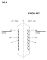
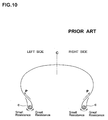
- the left and right bead portions have rotation resistances of asymmetric bead cores c with respect to a tire equator as schematically shown in Fig. 10.
- rotation deformation of the right bead portion with respect to the cord tension P of the carcass ply f is greater than that of the left bead portion, and a difference can be generated in impact absorption property.
- the rotation resistance of the left and right asymmetric bead cores c give different tensions to the carcass cords extending in the left and right sidewall portions during vulcanization formation of the tire, and varies intermediate elongations of the carcass cords and uniformity.
- a left and right asymmetric bead structure deteriorates stability at the time of cornering and this is not preferable.
- the present invention has been accomplished in view of the above circumstances, and it is a main object of the invention to provide a pneumatic tire capable of enhancing various tire performances by symmetrically exhibiting rotation resistances of a sheath on left and right bead portions.
- a pneumatic tire comprises a tread portion, a pair of sidewall portions, a pair of bead portions, a pair of bead cores each being disposed in the bead portion, each bead core comprising an annular core extending in the tire circumferential direction and a sheath including a plurality of sheath wires each extending helically around the annular core, a carcass comprising a carcass ply extending between the bead portions and turned up around the bead core in each bead portion, wherein one of the bead cores is reverse to the other bead core with respect to the helical direction of the sheath wire.
- tire 1 according to the present invention is for a motorcycle.
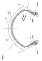
- the tire 1 in accordance with present invention comprises: a tread portion 2; a pair of sidewall portions 3; a pair of axially spaced bead portions 4 each with a bead core 5 therein; a carcass 6 extending between the bead cores 5; and a belt 7 disposed radially outside the carcass 6 in the tread portion 2.
- the tread portion 2 includes: a pair of tread edges 2e each being provided at axially outermost position of the tire; and a contact surface 2A contacting with a road between the tread edges 2e.
- the contact surface 2A is curved by a relatively small radius of curvature so as to protrude radially outwardly in a tire section including a tire axis.
- the carcass 6 comprises at least one ply of cords inclined at angle of from 65 to 90 degrees with respect to the tire equator C.
- the carcass 6 comprises two plies 6A and 6B.
- organic fiber cords e.g. aromatic polyamide, polyester, rayon, nylon and the like can be suitably used.
- steel cords may be used.
- Each carcass ply 6A and 6B extends between bead portions 4 and turned up around the bead core 5 in each bead portion from the axially inside to the outside of the tire so as to form a pair of turnup portions 6b and a main portion 6a therebetween.
- a rubber bead apex 8 extending and tapering from the bead core 5 is disposed between the main portion 6a and the turnup portion 6b in each bead portion 4.
- the belt 7 comprises two cross belt plies 7A and 7B of parallel cords laid at an angle of from 15 to 30 degrees with respect to the tire equator C.
- the belt cords steel cords, and high modulus organic fiber cords such as aramid, rayon and like can be used.
- the belt 7 may be composed of one belt ply. Further, the belt 7 can be made of a jointless belt by winding at least one cord or parallel cords spirally on the carcass 6.
- a band which covers with the belt 7 and has cords with an angle of not more than 5 degrees with respect to the tire equator can be disposed radially outside the belt 7 (not shown).
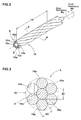
- the bead core 5 comprises an annular core 9, and at least one sheath 10 surrounding the annular core 9 and including a plurality of sheath wires 10a extending helically around the annular core 9 so as to form a so-called cable bead core.
- the bead core 5 has a cord structure of "1x1.5+6x1.4".
- the cord structure "1x1.5+6x1.4" means that the annular core 9 is made up of one wire having the diameter of 1.5 mm and one sheath 10 is made up of six sheath wires 10a each having the diameter of 1.4 mm.
- the annular core 9 a monofilament is preferably used.
- the annular core 9 may be made of synthetic resin material or metal material, and a steel wire is preferably used. Among them, in view of strength, steel wire with carbon content of from 0.1 to 0.9 % by weight is preferable.
- a diameter D1 of the annular core 9 is appropriately determined in accordance with size, category and the like of a tire, but if the diameter is excessively small, the strength of the bead core 5 is deteriorated, and if the diameter D1 is excessively large, the weight of the bead core is increased and outer diameter of the bead core 5 is increased. From such a point of view, the diameter D1 of the annular core 9 is preferably not less than 1.0 mm, and more preferably not less than 1.2 mm, the upper limit of the diameter D1 is not more than 2.2 mm, and more preferably not more than 2.0 mm.
- the sheath wire 10a a multi-filament or (preferably) a monofilament is used, and synthetic resin material or metal material is used for example.
- Preferable material of the monofilament is metal, and steel wire is especially preferable.
- hard materials such as piano wire defined in JIS G3502, and hard steel wire defined in JIS G3506 are especially preferable.
- Hard steel wire with carbon contents of 0.65 to 0.88 % by weight is especially preferable for the sheath wire 10a.
- a diameter D2 of the sheath wire 10a is not especially limited, but if it is excessively small, the strength of the bead core 5 tends to be deteriorated, and if the diameter D2 is excessively large, the weight of the tire and the diameter of the bead core 5 are increased. From such a view point, the diameter D2 of the sheath wire 10a is preferably not less than 0.9 mm and more preferably not less than 1.3 mm, the upper limit is preferably not more than 1.8 mm, and more preferably not more than 1.6 mm.
- a relation of the diameter D1 of the annular core 9 and the diameter D2 of the sheath wire 10a may be defined freely.
- the ratio (D2/D1) becomes small, the number of the sheath wires 10a is extremely increased, the rigidity of the bead core is increased, and there is an adverse possibility that large tension is given to the carcass ply. This limits slide movement of the carcass ply at the time of vulcanization and thus, elasticity may be deteriorated.
- the ratio (D2/D1) becomes large, the number of sheath wires 10a is reduced, the strength of the bead core 5 tends to be lowered.
- the ratio (D2/D1) is preferably not less than 0.5, more preferably not less than 0.7, and its upper limit is preferably not more than 2.0, and more preferably not more than 1.5.
- the number of the sheath wires 10a included in one layer of sheath 10 is appropriately determined in accordance with a relation or the like between the diameter of the sheath wire 10a and the spiral pitch TP at the time of winding.
- the number of sheath wires is preferably not less than 5, more preferably not less than 6, preferably not more than 13, more preferably not more than 10 and more preferably not more than 9.
- each sheath wire 10a contacts with the other wires in both sides.
- a surface of the annular core 9 and/or sheath wire 10a is plated with various materials (e.g., brass plating, bronze plating or zinc plating) in view of adhesion with respect to rubber and the like.
- the sheath 10 relatively rotates around the annular core 9, but easiness of rotation of the sheath 10 has directional property.
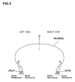
- the sheath 10 shows a large resistance with respect to rotation Ra in a direction in which the sheath wires 10a wound around the annular core 9 are helically wound (i.e., in a direction in which the sheath wires 10a are further wound), and the sheath 10 shows only a relatively small resistance with respect to rotation Rb in a direction in which the sheath wires 10a are loosened (i.e., in a direction in which the sheath wires 10a are untied).
- a helical direction of the sheath wire 10a of the bead core 5R disposed in the one bead portion 4R, and a helical direction of the sheath wire 10a of the bead core 5L disposed in the other bead portion 4L are reverse each other. This prevents the rotation directional property of the sheath 10 from affecting various performances of the pneumatic tire.
- the helical direction of the sheath wire 10a is determined based on the rotation direction when the sheath wires 10a are helically wound around the annular core 9.
- the winding of the sheath wire 10a around the core 9 in the clockwise direction is called the clockwise winding, and the winding thereof in the counterclockwise direction is called counterclockwise winding.
- the clockwise winding is "Z winding” defined in JISG3510 or JISL1017
- the counterclockwise winding is "S winding” defined in JIS.
- Fig. 4 is a perspective plan view of the pneumatic tire 1 for showing bead cores 5 as viewed from above.
- the sheath wire 10a of the right bead core 5R is wound in the clockwise direction
- the sheath wire 10a of the left bead core 5L is wound in the counterclockwise direction.
- the bead cores 5L and 5R are substantially the same except the helical directions of the sheath wires.
- Fig. 5 is a schematic sectional view of such a pneumatic tire 1.
- the right and left bead cores 5R and 5L are substantially symmetric with respect to the rotational direction in which the sheath is pulled by tension P of the cords of the carcass plies 6A and 6B such that the rotation resistance of the sheath 10 is small. Therefore, in left and right bead portions, the rotation resistances of the sheaths 10 can be reduced at the same level. This is effective for enhancing the vibration absorption property at the time of running.
- Fig. 6 is a perspective plan view of the pneumatic tire 1 for showing the bead cores 5 as viewed from above.
- sheath wires 10a of a right bead core 5R extend helically in the counterclockwise direction and sheath wires 10a of the left bead core 5L extend in the clockwise direction.
- Fig. 7 is a schematic sectional view of such a pneumatic tire 1.
- the right and left bead cores 5R and 5L are disposed symmetrically with respect to the rotational direction in which sheath is pulled by tension P of the cords of the carcass plies 6A and 6B such that the rotation resistance of the sheath 10 is great. Therefore, it becomes difficult to rotate the sheath 10 with respect to the cord tension P and thus, it is possible to provide a pneumatic tire 1 in which bead and sidewall rigidities are high, and steering stability is excellent.
- the rotation resistances of the sheaths 10 in the bead cores 5 are laterally symmetric.
- tension of the left and right carcass cords extending through each sidewall portion 3 can be substantially equal during vulcanization of the tire. Therefore, after the vulcanization formation, the path lengths of left and right carcass cords become substantially equal to each other, and a difference in intermediate elongations of the left and right carcass cords can be reduced.
- the same cornering operability and impact absorption property and the like can be exhibited in any of the left and right cornering directions.
- the motorcycle can stably run in both left and right cornering operations.
- Such a pneumatic tire has high uniformity and excellent steering stability.
- Such a pneumatic tire 1 has a tread pattern whose tread groove function is varied depending upon the rotational direction.
- a pneumatic tire 1 in which when the tire runs in accordance with the designated rotational direction F, the sheath wires 10a of the right bead core 5R are wound in the clockwise direction of the rotational direction F, and the sheath wires 10a of the left bead core 5L are wound in the counterclockwise direction of the rotational direction F.
- the bead cores 5L and 5R can maintain rotation resistances of the sheaths 10 with respect to the tension P of the cords at a small level and as a result, excellent impact absorption property can be exhibited.
- a pneumatic tire 1 in which when the tire rotates in accordance with the designated rotation direction F, the sheath wires 10a of the right bead core are wound in the counterclockwise direction of the rotational direction F, and the sheath wires 10a of the left bead core 5L are wound in the clockwise direction of the rotational direction F.
- the bead cores 5L and 5R can maintain rotation resistances of the sheaths 10 with respect to the tension P of the cords at a large level and as a result, the bead portion 4 can have high rigidity and steering stability is excellent.
- the tension P of the carcass cord which tries to rotate the sheath 10 of the bead core 5 becomes greater as the angle of the carcass cord with respect to the tire equator C is close to 90°. Therefore, the pneumatic tire of the present invention exhibits especially remarkable effect when the angle of the carcass cord is not less than 75 degrees, and more preferably not less than 85 degrees.
- the sheath 10 is composed of one layer, but the number of layer of the sheath 10 may be not less than two in accordance with required tire performance.
- the sheath wires 10a of each layer may be wound helically in the reverse direction between the left and right bead cores 5L and 5R. In that case, materials and/or diameters of sheath wires 10a may be different in each layer of the sheaths 10.
- the present invention is not limited to a pneumatic tire for an illustrated motorcycle, and the invention can be applied to various tires only if cable bead type bead core is used, such as a heavy load tire, a small truck tire, a motorcycle tire, an aircraft tire. Although especially preferable embodiments of the present invention have been described in detail, the invention is not limited to the illustrated embodiments, and the invention can be deformed in various modes and carried out.
- Pneumatic tires size: 120/70ZR17
- bead cores including the basic structure shown in Fig. 1 and Table 1 in which rotational direction was designated
- tire uniformity, intermediate elongation of the carcass cord and steering stability were tested.
- common specifications are as follows:
- Table 1 Ref.1 Ref.2 Ex. 1 Ex. 2 Helical direction of sheath wires of right bead core Clockwise direction Counterclockwise direction Clockwise direction Counterclockwise direction Helical direction of sheath wires of left bead core Clockwise direction Counterclockwise direction Counterclockwise direction Clockwise direction Result of test uniformity (indices) 100 99 94 95 Difference in intermediate elongation of left and right carcass cords (indices) 100 100 93 94 Straight running stability (on a scale from 1 to 10) 6.5 6.5 7.0 7.0 vibration absorption property of left cornering (on a scale from 1 to 10) 6.9 6.5 7.0 6.7 vibration absorption property of right cornering (on a scale from 1 to 10) 6.6 7.0 7.1 6.7 Difference of vibration absorption property at the time of left and right cornering 0.3 0.5 0.1 0
Landscapes
- Engineering & Computer Science (AREA)
- Mechanical Engineering (AREA)
- Tires In General (AREA)
- Ropes Or Cables (AREA)
Applications Claiming Priority (1)
| Application Number | Priority Date | Filing Date | Title |
|---|---|---|---|
| JP2005151282A JP4312173B2 (ja) | 2005-05-24 | 2005-05-24 | 自動二輪車用空気入りタイヤ |
Publications (3)
| Publication Number | Publication Date |
|---|---|
| EP1726459A2 true EP1726459A2 (de) | 2006-11-29 |
| EP1726459A3 EP1726459A3 (de) | 2008-10-15 |
| EP1726459B1 EP1726459B1 (de) | 2010-03-24 |
Family
ID=36939123
Family Applications (1)
| Application Number | Title | Priority Date | Filing Date |
|---|---|---|---|
| EP06007409A Ceased EP1726459B1 (de) | 2005-05-24 | 2006-04-07 | Luftreifen |
Country Status (6)
| Country | Link |
|---|---|
| US (1) | US20060266458A1 (de) |
| EP (1) | EP1726459B1 (de) |
| JP (1) | JP4312173B2 (de) |
| CN (1) | CN1868770B (de) |
| DE (1) | DE602006013065D1 (de) |
| TW (1) | TW200640716A (de) |
Families Citing this family (11)
| Publication number | Priority date | Publication date | Assignee | Title |
|---|---|---|---|---|
| JP5176295B2 (ja) * | 2006-07-07 | 2013-04-03 | 横浜ゴム株式会社 | 空気入りタイヤ |
| JP5089259B2 (ja) * | 2007-06-12 | 2012-12-05 | 住友ゴム工業株式会社 | 自動二輪車用空気入りタイヤ |
| JP5297503B2 (ja) * | 2011-06-13 | 2013-09-25 | 住友ゴム工業株式会社 | 自動二輪車用タイヤ |
| JP6074230B2 (ja) * | 2012-11-09 | 2017-02-01 | 住友ゴム工業株式会社 | 空気入りタイヤ、及びその製造方法 |
| CN103129328A (zh) * | 2013-03-13 | 2013-06-05 | 山东胜通钢帘线有限公司 | 工程巨胎用组合结构胎圈 |
| JP5973955B2 (ja) * | 2013-05-07 | 2016-08-23 | 住友ゴム工業株式会社 | 空気入りタイヤ |
| US11427959B2 (en) * | 2015-12-21 | 2022-08-30 | Nippon Sheet Glass Company, Limited | Rubber-reinforcing cord and rubber product using same |
| JP6247730B2 (ja) * | 2016-10-12 | 2017-12-13 | 住友ゴム工業株式会社 | 空気入りタイヤ、及びその製造方法 |
| JP2018070137A (ja) * | 2016-10-26 | 2018-05-10 | クムホ タイヤ カンパニー インコーポレーテッド | 空気入りタイヤ用ケーブルビード及びこれを備えた空気入りタイヤ |
| CN107953728B (zh) * | 2017-11-27 | 2020-02-11 | 江苏兴达钢帘线股份有限公司 | 一种缆型胎圈及轮胎 |
| WO2020031761A1 (ja) * | 2018-08-09 | 2020-02-13 | 株式会社ブリヂストン | 空気入りタイヤ |
Family Cites Families (6)
| Publication number | Priority date | Publication date | Assignee | Title |
|---|---|---|---|---|
| JP3096926B2 (ja) * | 1991-07-31 | 2000-10-10 | 横浜ゴム株式会社 | 空気入りラジアルタイヤ |
| JP3163449B2 (ja) * | 1991-12-27 | 2001-05-08 | 横浜ゴム株式会社 | 空気入りラジアルタイヤ |
| JP4428748B2 (ja) * | 1999-03-05 | 2010-03-10 | 株式会社ブリヂストン | 空気入りタイヤ |
| JP2001191752A (ja) * | 2000-01-13 | 2001-07-17 | Bridgestone Corp | 空気入りタイヤユニット及びその装着方法 |
| US6571847B1 (en) * | 2002-01-24 | 2003-06-03 | The Goodyear Tire & Rubber Company | Light weight alloy bead core |
| DE60316369T2 (de) * | 2002-02-14 | 2008-06-12 | Sumitomo Rubber Industries Ltd., Kobe | Luftreifen |
-
2005
- 2005-05-24 JP JP2005151282A patent/JP4312173B2/ja not_active Expired - Fee Related
-
2006
- 2006-04-07 EP EP06007409A patent/EP1726459B1/de not_active Ceased
- 2006-04-07 DE DE602006013065T patent/DE602006013065D1/de not_active Expired - Lifetime
- 2006-04-10 TW TW095112612A patent/TW200640716A/zh unknown
- 2006-04-17 US US11/404,910 patent/US20060266458A1/en not_active Abandoned
- 2006-04-17 CN CN2006100724901A patent/CN1868770B/zh not_active Expired - Fee Related
Also Published As
| Publication number | Publication date |
|---|---|
| US20060266458A1 (en) | 2006-11-30 |
| CN1868770B (zh) | 2010-04-21 |
| DE602006013065D1 (de) | 2010-05-06 |
| EP1726459B1 (de) | 2010-03-24 |
| EP1726459A3 (de) | 2008-10-15 |
| JP2006327318A (ja) | 2006-12-07 |
| TW200640716A (en) | 2006-12-01 |
| CN1868770A (zh) | 2006-11-29 |
| JP4312173B2 (ja) | 2009-08-12 |
Similar Documents
| Publication | Publication Date | Title |
|---|---|---|
| RU2427475C2 (ru) | Большегрузная радиальная шина | |
| EP2230099B1 (de) | Luftreifen | |
| JP3294378B2 (ja) | 空気入りタイヤ | |
| EP2607104B1 (de) | Luftreifen | |
| US20020011296A1 (en) | Pneumatic tire | |
| KR20010013459A (ko) | 경량 아라미드 벨트 레이디얼 타이어 | |
| EP1726459B1 (de) | Luftreifen | |
| US20220041017A1 (en) | Pneumatic tire | |
| US5419383A (en) | Pneumatic tire including hybrid belt cord | |
| US20080105352A1 (en) | Reduced weight aircraft tire | |
| JP2714341B2 (ja) | 空気入りタイヤ | |
| JP2021095124A (ja) | タイヤのベルト構造 | |
| JP4744392B2 (ja) | 自動二輪車用空気入りラジアルタイヤ | |
| WO2015156154A1 (ja) | タイヤ | |
| EP2300245B1 (de) | Motorradreifen | |
| JP2010274818A (ja) | 自動二輪車用空気入りタイヤ | |
| JP3837219B2 (ja) | 空気入りラジアルタイヤ | |
| JP3179915B2 (ja) | 空気入りタイヤ | |
| JP4153127B2 (ja) | 空気入りタイヤ | |
| US6637487B2 (en) | Pneumatic tire | |
| JP5013522B2 (ja) | 空気入りラジアルタイヤ | |
| JPH01141103A (ja) | 空気入りラジアルタイヤ | |
| JP4311725B2 (ja) | 空気入りタイヤ | |
| JPH05262104A (ja) | ライトトラック用ラジアルタイヤ | |
| JP2000062412A (ja) | 空気入りラジアルタイヤ |
Legal Events
| Date | Code | Title | Description |
|---|---|---|---|
| PUAI | Public reference made under article 153(3) epc to a published international application that has entered the european phase |
Free format text: ORIGINAL CODE: 0009012 |
|
| AK | Designated contracting states |
Kind code of ref document: A2 Designated state(s): AT BE BG CH CY CZ DE DK EE ES FI FR GB GR HU IE IS IT LI LT LU LV MC NL PL PT RO SE SI SK TR |
|
| AX | Request for extension of the european patent |
Extension state: AL BA HR MK YU |
|
| PUAL | Search report despatched |
Free format text: ORIGINAL CODE: 0009013 |
|
| AK | Designated contracting states |
Kind code of ref document: A3 Designated state(s): AT BE BG CH CY CZ DE DK EE ES FI FR GB GR HU IE IS IT LI LT LU LV MC NL PL PT RO SE SI SK TR |
|
| AX | Request for extension of the european patent |
Extension state: AL BA HR MK YU |
|
| 17P | Request for examination filed |
Effective date: 20090127 |
|
| 17Q | First examination report despatched |
Effective date: 20090225 |
|
| AKX | Designation fees paid |
Designated state(s): DE FR |
|
| GRAP | Despatch of communication of intention to grant a patent |
Free format text: ORIGINAL CODE: EPIDOSNIGR1 |
|
| GRAS | Grant fee paid |
Free format text: ORIGINAL CODE: EPIDOSNIGR3 |
|
| GRAA | (expected) grant |
Free format text: ORIGINAL CODE: 0009210 |
|
| AK | Designated contracting states |
Kind code of ref document: B1 Designated state(s): DE FR |
|
| REF | Corresponds to: |
Ref document number: 602006013065 Country of ref document: DE Date of ref document: 20100506 Kind code of ref document: P |
|
| PLBE | No opposition filed within time limit |
Free format text: ORIGINAL CODE: 0009261 |
|
| STAA | Information on the status of an ep patent application or granted ep patent |
Free format text: STATUS: NO OPPOSITION FILED WITHIN TIME LIMIT |
|
| 26N | No opposition filed |
Effective date: 20101228 |
|
| REG | Reference to a national code |
Ref country code: FR Ref legal event code: PLFP Year of fee payment: 11 |
|
| REG | Reference to a national code |
Ref country code: FR Ref legal event code: PLFP Year of fee payment: 12 |
|
| REG | Reference to a national code |
Ref country code: FR Ref legal event code: PLFP Year of fee payment: 13 |
|
| PGFP | Annual fee paid to national office [announced via postgrant information from national office to epo] |
Ref country code: FR Payment date: 20180315 Year of fee payment: 13 |
|
| PGFP | Annual fee paid to national office [announced via postgrant information from national office to epo] |
Ref country code: DE Payment date: 20180327 Year of fee payment: 13 |
|
| REG | Reference to a national code |
Ref country code: DE Ref legal event code: R119 Ref document number: 602006013065 Country of ref document: DE |
|
| PG25 | Lapsed in a contracting state [announced via postgrant information from national office to epo] |
Ref country code: DE Free format text: LAPSE BECAUSE OF NON-PAYMENT OF DUE FEES Effective date: 20191101 |
|
| PG25 | Lapsed in a contracting state [announced via postgrant information from national office to epo] |
Ref country code: FR Free format text: LAPSE BECAUSE OF NON-PAYMENT OF DUE FEES Effective date: 20190430 |