EP1726461A1 - Climatiseur destin aux vehicules - Google Patents
Climatiseur destin aux vehicules Download PDFInfo
- Publication number
- EP1726461A1 EP1726461A1 EP05720609A EP05720609A EP1726461A1 EP 1726461 A1 EP1726461 A1 EP 1726461A1 EP 05720609 A EP05720609 A EP 05720609A EP 05720609 A EP05720609 A EP 05720609A EP 1726461 A1 EP1726461 A1 EP 1726461A1
- Authority
- EP
- European Patent Office
- Prior art keywords
- air
- refrigerant
- cooling water
- refrigerant temperature
- air conditioner
- Prior art date
- Legal status (The legal status is an assumption and is not a legal conclusion. Google has not performed a legal analysis and makes no representation as to the accuracy of the status listed.)
- Withdrawn
Links
Images


Classifications
-
- B—PERFORMING OPERATIONS; TRANSPORTING
- B60—VEHICLES IN GENERAL
- B60H—ARRANGEMENTS OF HEATING, COOLING, VENTILATING OR OTHER AIR-TREATING DEVICES SPECIALLY ADAPTED FOR PASSENGER OR GOODS SPACES OF VEHICLES
- B60H1/00—Heating, cooling or ventilating devices
- B60H1/00642—Control systems or circuits; Control members or indication devices for heating, cooling or ventilating devices
- B60H1/00814—Control systems or circuits characterised by their output, for controlling particular components of the heating, cooling or ventilating installation
- B60H1/00821—Control systems or circuits characterised by their output, for controlling particular components of the heating, cooling or ventilating installation the components being ventilating, air admitting or air distributing devices
- B60H1/00828—Ventilators, e.g. speed control
-
- B—PERFORMING OPERATIONS; TRANSPORTING
- B60—VEHICLES IN GENERAL
- B60H—ARRANGEMENTS OF HEATING, COOLING, VENTILATING OR OTHER AIR-TREATING DEVICES SPECIALLY ADAPTED FOR PASSENGER OR GOODS SPACES OF VEHICLES
- B60H1/00—Heating, cooling or ventilating devices
- B60H1/00357—Air-conditioning arrangements specially adapted for particular vehicles
- B60H1/00385—Air-conditioning arrangements specially adapted for particular vehicles for vehicles having an electrical drive, e.g. hybrid or fuel cell
- B60H1/00392—Air-conditioning arrangements specially adapted for particular vehicles for vehicles having an electrical drive, e.g. hybrid or fuel cell for electric vehicles having only electric drive means
-
- B—PERFORMING OPERATIONS; TRANSPORTING
- B60—VEHICLES IN GENERAL
- B60H—ARRANGEMENTS OF HEATING, COOLING, VENTILATING OR OTHER AIR-TREATING DEVICES SPECIALLY ADAPTED FOR PASSENGER OR GOODS SPACES OF VEHICLES
- B60H1/00—Heating, cooling or ventilating devices
- B60H1/00642—Control systems or circuits; Control members or indication devices for heating, cooling or ventilating devices
- B60H1/00814—Control systems or circuits characterised by their output, for controlling particular components of the heating, cooling or ventilating installation
- B60H1/00878—Control systems or circuits characterised by their output, for controlling particular components of the heating, cooling or ventilating installation the components being temperature regulating devices
- B60H1/00899—Controlling the flow of liquid in a heat pump system
Definitions
- the present invention relates to an air conditioner for a vehicle, and more particularly, to an air conditioner for a vehicle suitable for electric cars and fuel cell cars (hereinafter, "electric car or the like").
- blower fan control is effective because the cooling water is heated with time once the engine is started.
- a vehicle such as an electric car or the like that does not have a heat source which uses the engine cooling water, since air conditioner wind is heated by heat of refrigerant, it is difficult to apply the blower fan control.
- a first aspect of the present invention provides an air conditioner for a vehicle that blows air heated by a refrigerant as a heat source into a vehicle interior to heat the vehicle interior
- the air conditioner for a vehicle including: a refrigerant temperature detector that detects a temperature of the refrigerant (hereinafter, "refrigerant temperature”); and a controller that blows a normal set quantity of air into the vehicle interior when the refrigerant temperature detected by the refrigerant temperature detector reaches a prescribed value and that limits blow of air into the vehicle interior when the refrigerant temperature does not reach the prescribed value.
- the controller may blow, into the vehicle interior, a small quantity of air determined according to the refrigerant temperature until the refrigerant temperature detected by the refrigerant temperature detector reaches the prescribed value.
- the controller may blow, into the vehicle interior, a small quantity of air determined according to time elapsed after the air conditioner is actuated until the refrigerant temperature detected by the refrigerant temperature detector reaches the prescribed value.
- the controller may blow, into the vehicle interior, greater one of a small quantity of air determined according to the refrigerant temperature and a small quantity of air determined according to time elapsed after the air conditioner is actuated, until the refrigerant temperature detected by the refrigerant temperature detector reaches the prescribed value.
- a second aspect of the invention provides an air conditioner for a vehicle that blows, into a vehicle interior, at least one of air heated by a refrigerant as a heat source and air heated by engine cooling water as the heat source, thereby heating the vehicle interior
- the air conditioner for a vehicle including: a refrigerant temperature detector that detects the refrigerant temperature; a cooling water temperature detector that detects a temperature of the cooling water (hereinafter, "cooling water temperature"); and a controller that blows a normal set quantity of air into the vehicle interior when one of the refrigerant temperature detected by the refrigerant temperature detector and the cooling water temperature detected by the cooling water temperature detector reaches a prescribed value, and that, when both of the refrigerant temperature and the cooling water temperature do not reach the prescribed value, limits blow of air into the vehicle interior until one of the refrigerant temperature and the cooling water temperature reaches the prescribed value.
- the controller may blow the normal set quantity of air into the vehicle interior in a state in which a ratio at which cooling water is used as the heat source is variable.
- the controller may blow the normal set quantity of air into the vehicle interior in a state in which a ratio at which the cooling water is used as the heat source is zero.
- the controller may limit the blow of air into the vehicle interior until either one of the cooling water temperature and the refrigerant temperature reaches the prescribed value.
- the controller may blow, into the vehicle interior, greater one of a small quantity of air determined according to the refrigerant temperature and a small quantity of air determined according to the cooling water temperature when both of the cooling water temperature detected by the cooling water temperature detector and the refrigerant temperature detected by the refrigerant temperature detector do not reach the prescribed value.
- the quantity of air is set to a greater one of a small quantity of air determined according to the refrigerant temperature and a small quantity of air determined according to the cooling water temperature. Therefore, it is possible to further enhance the rising speed of the interior temperature.
- the controller may blow, into the vehicle interior, the greatest one of a small quantity of air determined according to the refrigerant temperature detected by the refrigerant temperature detector, a small quantity of air determined according to the cooling water temperature detected by the cooling water temperature detector, and a small quantity of air determined according to time elapsed after the air conditioner is actuated, when both of the cooling water temperature and the refrigerant temperature do not reach the prescribed value.
- the quantity of air is set to the greatest one of a small quantity of air determined according to the refrigerant temperature, a small quantity of air determined according to the cooling water temperature, and a small quantity of air determined according to the elapsed time after actuation. Therefore, it is possible to further enhance the rising speed of the interior temperature.
- Fig. 1 is a schematic configuration diagram of an air conditioner for a vehicle according to a first embodiment.
- the air conditioner for a vehicle which is applied to an electric car or the like, in which refrigerant is used as a heat source will be explained.
- the air conditioner for a vehicle of the embodiment includes a heating cycle (shown with - ⁇ in the drawing) which circulates carbon dioxide as the refrigerant to exchange heat between the refrigerant and air.
- the heating cycle includes a compressor 101, a sub-heat exchanger 102 (internal heat exchanger 103), an expansion valve 104, an exterior heat exchanger 105, and an accumulator 106 that are communication-connected with one another through pipes in this order, and refrigerant compressed by the compressor 101 is circulated through these members.
- the compressor 101 obtains a driving force from a motor (not shown) and compresses gas-phase carbon dioxide, and discharges the compressed carbon dioxide as high-temperature and high-pressure refrigerant.
- the sub-heat exchanger 102 is disposed in an air conditioner duct 118, and heats air conditioner wind sent from a blower fan 107 by refrigerant supplied from the compressor 101.
- An air mix door 108 whose opening degree (mixing ratio) is freely controlled by a controller 117 is provided at a front surface of the sub-heat exchanger 102.
- the air mix door 108 is controlled such that when air conditioner wind from the blower fan 107 is heated by the sub-heat exchanger 102, it is turned downward by a predetermined amount (mixing ratio is 0 to 100%) according to a required heating temperature, and when the air conditioner wind is not heated, it is turned upward (mixing ratio is 0%).
- a refrigerant temperature sensor 116 that detects the refrigerant temperature is connected to a pipe on the side of an outlet of the sub-heat exchanger 102.
- the refrigerant temperature sensor 116 can be disposed anywhere at a high-temperature and high-pressure position from a refrigerant discharge port of the compressor 101 to an inlet of the expansion valve 104.
- the expansion valve 104 decompresses (expands) and outputs a high-pressure refrigerant sent from the sub-heat exchanger 102 through the internal heat exchanger 103.
- the exterior heat exchanger 105 exchanges heat between outside air and low-pressure refrigerant sent from the expansion valve 104, and absorbs the heat.
- the accumulator 106 separates refrigerant discharged from the exterior heat exchanger 105 into gas and liquid. Of the gas and the liquid, the accumulator 106 sends only the gas refrigerant to the internal heat exchanger 103, and temporarily stores the liquid refrigerant.
- the blower fan 107 generates air conditioner wind of a quantity corresponding to a voltage level instructed from the controller 117, described later.
- the high-temperature and high-pressure refrigerant compressed by the compressor 101 is sent to the sub-heat exchanger 102, and the air conditioner wind is heated by heat exchange therein. Then, the refrigerant bypasses the exterior heat exchanger 105 and flows into a solenoid valve 114 (a three-way valve 115 is closed), and is sent to the expansion valve 104 through the internal heat exchanger 103. The refrigerant is then decompressed by the expansion valve 104 and its heat is exchanged with (absorbed by) outside air in the exterior heat exchanger 105, and the refrigerant returns to the compressor 101 from the three-way valve 115 through the accumulator 106 and the internal heat exchanger 103.
- the air conditioner for a vehicle also includes a cooling cycle ( ⁇ in the drawings).
- the compressor 101, the sub-heat exchanger 102, the exterior heat exchanger 105, an expansion valve 109, an interior heat exchanger 110, the accumulator 106, and the internal heat exchanger 103 are connected to one another through pipes in this order in the cooling cycle, so that refrigerant compressed by the compressor 101 is circulated through these members.
- the expansion valve 109 decompresses (expands) and outputs high-pressure refrigerant sent from the internal heat exchanger 103.
- the internal heat exchanger 103 exchanges heat between refrigerant whose heat is dissipated by the exterior heat exchanger 105 and refrigerant evaporated by the interior heat exchanger 110.
- the interior heat exchanger 110 is disposed in the air conditioner duct 118, and cools air conditioner wind blown out from the blower fan 107 by low-temperature and low-pressure refrigerant decompressed (expanded) by the expansion valve 109. If the air conditioner wind from the blower fan 107 passes through the interior heat exchanger 110, heat thereof is exchanged with the refrigerant decompressed by the expansion valve 109, and cool air is supplied into the vehicle interior.
- the controller 117 includes a microcomputer including a CPU, a ROM, and a RAM.
- the controller 117 receives various pieces of data from various sensors such as the refrigerant temperature sensor 116 and from a timer (not shown) periodically or if necessary, performs computation based on programs of the blower fan controls (1) to (4) stored in the ROM and based on the various pieces of data, switches between the solenoid valve 114 and the three-way valve 115, and controls the quantity (hereinafter, "fan speed") of air of the blower fan 107 and the opening degree of the air mix door 108.
- various sensors such as the refrigerant temperature sensor 116 and from a timer (not shown) periodically or if necessary, performs computation based on programs of the blower fan controls (1) to (4) stored in the ROM and based on the various pieces of data, switches between the solenoid valve 114 and the three-way valve 115, and controls the quantity (hereinafter, "fan speed") of air of the blower fan 107 and the opening degree of the air mix door 108.
- the controller 117 starts the routine of the blower fan control (1) as the air conditioner is actuated, and determines whether the fan speed is automatically controlled at step S 1.
- the automatic control means that the fan speed is optimally set based on a set temperature and a vehicle interior temperature within a refrigerant temperature range higher than a given value.
- step S1 the procedure proceeds to step S5 at which the blower fan 107 is controlled at a fan speed of a level instructed by a user. If the control is the automatic control, the procedure proceeds to step S2 at which it is determined whether the refrigerant temperature detected by the refrigerant temperature sensor 116 is equal to or higher than tp3 (prescribed value). If the refrigerant temperature is equal to or higher than the refrigerant temperature tp3, the procedure proceeds to step S3 at which the normal automatic control is carried out.
- the refrigerant temperature tp3 is a boundary value used for determining whether the blower fan control (1) can be carried out by the routine.
- the blower fan 107 is controlled at a fan speed by the normal automatic control.
- the procedure proceeds to step S4, at which the fan speed OFF state is maintained. In this case, uncomfortable cool air is not sent from the vent.
- the controller 117 controls the fan speed of the blower fan 107 while proceeding through the steps S 1 to S5.
- blower fan control (1) since the fan speed OFF is selected if the refrigerant temperature is low, uncomfortable cool air is not sent out as compared with the conventional technique in which air is sent immediately after the air conditioner is actuated, and the blower fan can be controlled appropriately for a driver or the like on the vehicle.
- FIG. 4 is a graph showing a relation between the refrigerant temperature and the fan speed.
- step S 14 the fan speed corresponding to the refrigerant temperature detected by the refrigerant temperature sensor 116 is obtained from the graph shown in Fig. 4, and the fan speed is set to this value.
- the fan speeds 0 to 2 are set in a range of a small air quantity at which a driver or the like does not feel uncomfortable, and the fan speed is set in stages in a range of refrigerant temperatures tp0 to tp3.
- the fan speed is set to 0 when the refrigerant temperature is tp0 to lower than tp1, the fan speed is set to 1 when the refrigerant temperature is tp 1 to lower than tp2, and the fan speed is set to 2 when the refrigerant temperature is tp2 to lower than tp3, and the blower fan 107 is controlled such that the fan speed becomes equal to the set value.
- the hatched region in Fig. 4 shows a region of the fan speed and the refrigerant temperature where the automatic control is carried out.
- the controller 117 controls the fan speed of the blower fan 107 while proceeding through the steps S 1 to S 14.
- blower fan control (2) even when the refrigerant temperature is low, a small quantity of air is sent so that a driver or the like does not feel uncomfortable. Therefore, uncomfortable cool air is not sent out as compared with the conventional technique in which air is sent immediately after the air conditioner is actuated, which enhances the rising speed of an interior temperature as compared with when air sending operation is stopped until the refrigerant temperature reaches a given value. Therefore, the blower fan can be controlled more appropriately for a driver or the like on the vehicle.
- FIG. 6 is a graph showing a relation between the fan speed and elapsed time after the air conditioner is actuated.
- step S24 a fan speed corresponding to elapsed time from the actuation of the air conditioner measured by the timer (not shown) is obtained from the graph shown in Fig. 6, and the fan speed is set to this value.
- the fan speeds 0 to 2 are set in a range of a small air quantity at which a driver or the like does not feel uncomfortable, and the fan speed is set in stages in a range of elapsed time t0 to t3.
- the fan speed is set to 0 when the elapsed time is t0 to less than t1, the fan speed is set to 1 when the elapsed time is t1 to less than t2, and the fan speed is set to 2 when the elapsed time is t2 or less than t3, and the blower fan 107 is controlled such that the fan speed becomes equal to the set value.
- the controller 117 controls the fan speed of the blower fan 107 while proceeding through the steps S 1 to S24.
- the blower fan control (3) even when the refrigerant temperature is low, a small quantity of air is sent so that a driver or the like does not feel uncomfortable. Therefore, uncomfortable cool air is not sent out as compared with the conventional technique in which air is sent immediately after the air conditioner is actuated. Even when the temperature rise of the refrigerant is slow after the air conditioner is actuated, since a small quantity of air is sent after a predetermined time has elapsed, anxiety of a driver or the like that the air conditioner for a vehicle has broken since it does not operate after actuating it, can be removed. Further, since the rising speed of an interior temperature is enhanced as compared with when air sending operation is stopped until the refrigerant temperature reaches a given value, the blower fan can be controlled more appropriately for a driver or the like on the vehicle.
- step S34 a fan speed fre_fan corresponding to the refrigerant temperature detected by the refrigerant temperature sensor 116 is obtained from the graph shown in Fig. 4.
- step S35 a fan speed time_fan corresponding to elapsed time after the air conditioner is actuated measured by the timer (not shown) is obtained from the graph shown in Fig. 6.
- step S36 at which the fan speed fre_fan and the fan speed time_fan are compared with each other to determine which is greater.
- step S37 At which the fan speed is set to fre_fan, and the blower fan 107 is controlled such that the fan speed becomes equal to this value. If the fan speed time_fan is greater than the fan speed fre_fan at step S36, the procedure proceeds to step S38, at which the fan speed is set to the time_fan, and the blower fan 107 is controlled such that the fan speed becomes equal to this value.
- the controller 117 controls the fan speed of the blower fan 107 while proceeding through the steps S1 to S38.
- blower fan control (4) even when the refrigerant temperature is low, a small quantity of air is sent so that a driver or the like does not feel uncomfortable. Therefore, uncomfortable cool air is not sent out as compared with the conventional technique in which air is sent immediately after the air conditioner is actuated. Even when the temperature rise of the refrigerant is slow after the air conditioner is actuated, since a small quantity of air is sent after a predetermined time has elapsed, anxiety of a driver or the like that the air conditioner for a vehicle has broken since it does not operate after actuating it, can be removed. Greater one of the fan speed by the refrigerant temperature and the fan speed by the elapsed time is set as the fan speed. This further enhances the rising speed of the interior temperature and thus, the blower fan can be controlled more appropriately for a driver or the like on the vehicle.
- Fig. 8 is a schematic configuration diagram of an air conditioner for a vehicle according to a second embodiment.
- Like reference signs denote like parts as those shown in Fig. 1, and bold lines shows paths of the heating cycle, and broken lines show paths of the cooling cycle (explanation thereof is omitted).
- the air conditioner for a vehicle of this embodiment is applied to an engine vehicle.
- Engine cooling water, carbon dioxide, and refrigerant are used as heat sources.
- the configuration of this embodiment can be applied to R134a refrigerant.
- the internal heat exchanger 103 is not a fundamental element.
- a heater core 119 is disposed in the air conditioner duct 118, and engine cooling water flowing through a cooling passage of an engine 120 is circulated through a pipe.
- the heater core 119 heats the air conditioner wind sent out from the blower fan 107 by the engine cooling water.
- a water temperature sensor 121 that detects the temperature of the engine cooling water (hereinafter, “cooling water temperature”) is connected to a pipe of the engine cooling water.
- the air mix door 108 is controlled such that when air conditioner wind from the blower fan 107 is heated by the heater core 119, it is turned downward by a predetermined amount (mixing ratio is 0 to 100%) according to a required heating temperature, and when the air conditioner wind is not heated, it is turned upward (mixing ratio is 0%). That is, the mixing ratio is controlled in a range of 0 to 100% as a ratio at which the engine cooling water is used as the heat source.
- the connection between the compressor 101, the exterior heat exchanger 105, the internal heat exchanger 103, and the interior heat exchanger 110 is switched by a four-way valve 122.
- a controller 117A of this embodiment includes a microcomputer including a CPU, a ROM, and a RAM.
- the controller 117A receives various pieces of data from various sensors such as the refrigerant temperature sensor 116 and the water temperature sensor 121 and from a timer (not shown) periodically or if necessary, performs computation based on programs of the blower fan controls (5) to (8) stored in the ROM and based on the various pieces of data, switches the four-way valve 122, and controls the fan speed of the blower fan 107 and the opening degree of the air mix door 108.
- the controller 117A starts a routine of the blower fan control (5) as the engine and the air conditioner are started (hereinafter, "system startup").
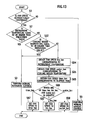
- step S1 the controller 117A determines whether the fan speed is automatically controlled. If the fan speed is not automatically controlled, the procedure proceeds to step S5, at which the blower fan 107 is controlled at a fan speed of a level instructed by a user. If the fan speed is automatically controlled, the procedure proceeds to step S2, at which it is determined whether the refrigerant temperature detected by the refrigerant temperature sensor 116 is equal to or higher than tp3 (prescribed value). If the refrigerant temperature is equal to or higher than the refrigerant temperature tp3, the procedure proceeds to step S3, at which the normal automatic control is carried out.
- the blower fan 107 is controlled at a fan speed of the normal automatic control. If the refrigerant temperature is lower than the refrigerant temperature tp3 at step S2, the procedure proceeds to step S32, at which it is determined whether the cooling water temperature detected by the water temperature sensor 121 is equal to or higher than tp3' (prescribed value). If the cooling water temperature is equal to or higher than the cooling water temperature tp3', the procedure proceeds to step S3, at which the normal automatic control is carried out.
- step S32 If the cooling water temperature is equal to or higher than the cooling water temperature tp3', since the air conditioner wind of a temperature that is not uncomfortable to a driver or the like is sent, the blower fan 107 is controlled at a fan speed of the normal automatic control. If the cooling water temperature is lower than the cooling water temperature tp3' at step S32, the procedure proceeds to step S4, at which the fan speed OFF state is maintained. In this case, uncomfortable cool air is not sent from the vent.
- the controller 117A controls the fan speed of the blower fan 107 while proceeding through the steps S 1 to S32.
- blower fan control (5) since the fan speed OFF is selected when the refrigerant temperature and the cooling water temperature are low, uncomfortable cool air is not sent out as compared with the conventional technique in which air is sent immediately after the air conditioner is actuated and thus, the blower fan can be controlled appropriately for a driver or the like on the vehicle.
- step S1 if the automatic control is carried out at step S1, the procedure proceeds to step S32, at which it is determined whether the cooling water temperature detected by the water temperature sensor 121 is equal to or higher than tp3'. If the cooling water temperature is equal to or higher than the cooling water temperature tp3', the procedure proceeds to step S43, at which the mixing ratio is set to a variable value within a range of 0 to 100% and then, the procedure proceeds to step S3, at which the normal automatic control is carried out. In this manner, when the cooling water temperature is relatively high, the mixing ratio is appropriately set according to the cooling water temperature, thereby further swiftly increasing the interior temperature.
- step S2 determines whether the refrigerant temperature detected by the refrigerant temperature sensor 116 is equal to or higher than tp3. If the refrigerant temperature is equal to or higher than tp3, the procedure proceeds to step S42, at which the mixing ratio is fixed to 0% and then, the procedure proceeds to step S3, at which the normal automatic control is carried out. In this manner, when the cooling water temperature is low and the refrigerant temperature is relatively high, the mixing ratio is set to 0% to prevent cool air conditioner wind from hitting the heater core 119, thereby further swiftly increasing the interior temperature. If the refrigerant temperature is lower than tp3 at step S2, the procedure proceeds to step S4, at which the fan speed OFF state is maintained. In this case, uncomfortable cool air is not sent from the vent.
- the controller 117A controls the fan speed of the blower fan 107 while proceeding through the steps S 1 to S43.
- the blower fan control (6) when the cooling water temperature and the refrigerant temperature are low, the fan speed OFF is selected and thus, uncomfortable cool air is not sent out as compared with the conventional technique in which air is sent immediately after the air conditioner is actuated and thus, the blower fan can be controlled appropriately for a driver or the like on the vehicle. Since the mixing ratio is appropriately set according to the cooling water temperature and the refrigerant temperature, it is possible to enhance the rising speed of the interior temperature. Thus, the blower fan can be controlled appropriately for a driver or the like on the vehicle.
- Fig. 12 is a graph showing a relation between the cooling water temperature and the fan speed.
- step S 1 if the automatic control is carried out at step S 1, the procedure proceeds to step S2, at which it is determined whether the refrigerant temperature detected by the refrigerant temperature sensor 116 is equal to or higher than tp3. If the refrigerant temperature is equal to or higher than the refrigerant temperature tp3, the procedure proceeds to step S3, at which the normal automatic control is carried out. If the refrigerant temperature is lower than the refrigerant temperature tp3 at step S2, the procedure proceeds to step S32, at which it is determined whether the cooling water temperature detected by the water temperature sensor 121 is equal to or higher than tp3'.
- step S3 If the cooling water temperature is equal to or higher than the cooling water temperature tp3', the procedure proceeds to step S3. In this manner, when the refrigerant temperature is equal to or higher than the refrigerant temperature tp3 or when the cooling water temperature is equal to or higher than the cooling water temperature tp3', air conditioner wind of a temperature at which a driver does not feel uncomfortable is sent out, and the blower fan 107 is controlled at a fan speed by the normal automatic control.
- step S54 a fan speed fre_fan corresponding to the refrigerant temperature detected by the refrigerant temperature sensor 116 is obtained from the graph shown in Fig. 4.
- step S55 a fan speed water_fan corresponding to the cooling water temperature detected by the water temperature sensor 121 is obtained from the graph shown in Fig. 12.
- the fan speeds 0 to 2 are set in a range of a small air quantity at which a driver or the like does not feel uncomfortable, and the fan speed is set in stages in a range of the cooling water temperatures tp0' to tp3'.
- the fan speed is set to 0 when the cooling water temperature is tp0' to lower than tp1', the fan speed is set to 1 when the cooling water temperature is tp1' to lower than tp2', and the fan speed is set to 2 when the cooling water temperature is tp2' to lower than tp3', and the blower fan 107 is controlled such that the fan speed becomes equal to the set value.
- step S56 the fan speed fre_fan and the fan speed water_fan are compared with each other to determine which is greater.
- the procedure proceeds to step S57, at which the fan speed is set to fre_fan, and the blower fan 107 is controlled such that the fan speed becomes equal to the fre_fan.
- step S58 the fan speed is set to water_fan, and the blower fan 107 is controlled such that the fan speed becomes equal to water_fan.
- the controller 117A controls the fan speed of the blower fan 107 while proceeding through the steps S1 to S58.
- blower fan control (7) even when the refrigerant temperature or the cooling water temperature is low, a small quantity of air is sent so that a driver or the like does not feel uncomfortable. Therefore, uncomfortable cool air is not sent out as compared with the conventional technique in which air is sent immediately after the air conditioner is actuated. Greater one of the fan speed determined according to the refrigerant temperature and the fan speed determined according to the cooling water temperature is employed as the fan speed, so it is possible to further enhance the rising speed of the interior temperature and thus, the blower fan can be controlled more appropriately for a driver or the like on the vehicle.
- Fig. 12 is a graph showing a relation between the cooling water temperature and the fan speed.
- step S54 step of obtaining fan speed fre_fan corresponding to the refrigerant temperature
- step S55 step of obtaining fan speed water_fan corresponding to the cooling water temperature
- the procedure proceeds to step S65, at which fan speed time_fan corresponding to time elapsed after the system startup measured by the timer (not shown) is obtained from the graph shown in Fig. 6 (lateral axis shows time elapsed after the system startup).
- step S66 the fan speed time_fan, the fan speed fre_fan, and the fan speed water_fan are compared with one another to determine which one of them is the greatest. If the fan speed time_fan is the greatest, the procedure proceeds to step S67, at which the fan speed is set to time_fan, and the blower fan 107 is controlled such that the fan speed becomes equal to time_fan. If the fan speed fre_fan is the greatest, the procedure proceeds to step S57, at which the fan speed is set to fre_fan, and the blower fan 107 is controlled such that the fan speed becomes equal to fre_fan. If the fan speed water_fan is the greatest, the procedure proceeds to step S58, at which the fan speed is set to water_fan, and the blower fan 107 is controlled such that the fan speed becomes equal to water_fan.
- the controller 117A controls the fan speed of the blower fan 107 while proceeding through the steps S1 to S67.
- the blower fan control (8) even when the refrigerant temperature or the cooling water temperature is low, a small quantity of air is sent so that a driver or the like does not feel uncomfortable. Therefore, uncomfortable cool air is not sent out as compared with the conventional technique in which air is sent immediately after the air conditioner is actuated, and the fan speed is set to the greatest one of the fan speed determined by the refrigerant temperature, the fan speed determined by the cooling water temperature, and the fan speed determined by time elapsed after the system startup. Therefore, it is possible to further enhance the rising speed of the interior temperature. Thus, the blower fan can be controlled more appropriately for a driver or the like on the vehicle.
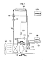
- Fig. 14 is a schematic configuration diagram for showing another example of a configuration of an air conditioner for a vehicle to which the blower fan control of the second embodiment can be applied.
- Like reference signs denote like parts as those shown in Figs. 1 and 8 (however, connection and disposition are partially different).
- This embodiment is applied to an engine vehicle, and the engine cooling water and R134a refrigerant are used as the heat sources (however, the refrigerant is not limited to R134a).
- the sub-heat exchanger 102 and the heater core 119 are disposed in the air conditioner duct 118.
- the sub-heat exchanger 102 is used when the heater is started, and the three-way valve 115 is switched when the refrigerant temperature becomes high.
- the path from the compressor 101 is switched toward the exterior heat exchanger 105 by the three-way valve 115.
- the mixing ratio of the air mix door 108 is set to a variable value within a range of 0 to 100%.
- a controller 117B includes a microcomputer including a CPU, a ROM, and a RAM.
- the controller 117B receives various pieces of data from various sensors such as the refrigerant temperature sensor 116 and the water temperature sensor 121 and from a timer (not shown) periodically or if necessary, performs computation based on programs of the blower fan controls (5), (7), (8) stored in the ROM and based on the various pieces of data, switches the three-way valve 115, and controls the fan speed of the blower fan 107 and the opening degree of the air mix door 108.
- the same effect as that of the second embodiment can be obtained by executing the blower fan controls (5), (7), (8) in the controller 117B.
Landscapes
- Engineering & Computer Science (AREA)
- Physics & Mathematics (AREA)
- Thermal Sciences (AREA)
- Mechanical Engineering (AREA)
- Life Sciences & Earth Sciences (AREA)
- Sustainable Development (AREA)
- Sustainable Energy (AREA)
- Air-Conditioning For Vehicles (AREA)
Applications Claiming Priority (2)
| Application Number | Priority Date | Filing Date | Title |
|---|---|---|---|
| JP2004076013A JP2005262948A (ja) | 2004-03-17 | 2004-03-17 | 車両用空調装置 |
| PCT/JP2005/004338 WO2005087524A1 (fr) | 2004-03-17 | 2005-03-11 | Climatiseur destiné aux véhicules |
Publications (2)
| Publication Number | Publication Date |
|---|---|
| EP1726461A1 true EP1726461A1 (fr) | 2006-11-29 |
| EP1726461A4 EP1726461A4 (fr) | 2009-04-01 |
Family
ID=34975438
Family Applications (1)
| Application Number | Title | Priority Date | Filing Date |
|---|---|---|---|
| EP05720609A Withdrawn EP1726461A4 (fr) | 2004-03-17 | 2005-03-11 | Climatiseur destin aux vehicules |
Country Status (4)
| Country | Link |
|---|---|
| US (1) | US20080229768A1 (fr) |
| EP (1) | EP1726461A4 (fr) |
| JP (1) | JP2005262948A (fr) |
| WO (1) | WO2005087524A1 (fr) |
Cited By (1)
| Publication number | Priority date | Publication date | Assignee | Title |
|---|---|---|---|---|
| US9539880B2 (en) | 2011-07-05 | 2017-01-10 | Denso Corporation | Air conditioner for vehicle |
Families Citing this family (16)
| Publication number | Priority date | Publication date | Assignee | Title |
|---|---|---|---|---|
| DE102008059886A1 (de) * | 2008-12-03 | 2010-06-10 | GM Global Technology Operations, Inc., Detroit | Belüftungssystem für ein Kraftfahrzeug, Verfahren zur Klimatisierung eines Kraftfahrzeuges |
| US20100190429A1 (en) * | 2009-01-26 | 2010-07-29 | Ford Global Technologies, Llc | Variable hvac airflow control |
| JP2011020478A (ja) * | 2009-07-13 | 2011-02-03 | Denso Corp | 車両用空調装置 |
| JP5126173B2 (ja) * | 2009-07-13 | 2013-01-23 | 株式会社デンソー | 車両用空調装置 |
| JP5310323B2 (ja) * | 2009-07-06 | 2013-10-09 | 株式会社デンソー | 車両用空調装置の制御方法 |
| EP2878468B1 (fr) * | 2012-07-24 | 2018-06-06 | Japan Climate Systems Corporation | Dispositif de climatisation pour véhicule |
| JP6049339B2 (ja) * | 2012-07-24 | 2016-12-21 | 株式会社日本クライメイトシステムズ | 車両用空調装置 |
| US20140190678A1 (en) * | 2013-01-07 | 2014-07-10 | Ford Global Technologies, Llc | Personalized vehicle climate control |
| JP6197745B2 (ja) * | 2013-07-31 | 2017-09-20 | 株式会社デンソー | 車両用冷凍サイクル装置 |
| KR101610539B1 (ko) * | 2014-11-13 | 2016-04-07 | 현대자동차주식회사 | 차량용 공조장치의 증발기 표면의 미생물 번식 억제 장치 및 방법 |
| JP6323489B2 (ja) * | 2015-08-04 | 2018-05-16 | 株式会社デンソー | ヒートポンプシステム |
| CN108136873B (zh) * | 2015-10-01 | 2021-02-23 | 株式会社电装 | 车辆用空调装置 |
| JP2017165139A (ja) * | 2016-03-14 | 2017-09-21 | カルソニックカンセイ株式会社 | 空調装置 |
| JP6705387B2 (ja) * | 2017-01-16 | 2020-06-03 | トヨタ自動車株式会社 | 蓄電装置の冷却システム |
| JP6791075B2 (ja) * | 2017-09-19 | 2020-11-25 | トヨタ自動車株式会社 | 蓄電装置の冷却システム |
| DE102019213860A1 (de) * | 2019-09-11 | 2021-03-11 | Mahle International Gmbh | Klimatisierungssystem für ein Kraftfahrzeug |
Family Cites Families (8)
| Publication number | Priority date | Publication date | Assignee | Title |
|---|---|---|---|---|
| JPH0232493Y2 (fr) * | 1985-05-14 | 1990-09-04 | ||
| DE3688523T2 (de) * | 1985-11-27 | 1994-01-13 | Nippon Denso Co | Kraftfahrzeugklimaanlage. |
| JPH0761763B2 (ja) * | 1987-12-21 | 1995-07-05 | 日産自動車株式会社 | 自動車用空調装置 |
| JPH0258129A (ja) | 1988-08-24 | 1990-02-27 | Agency Of Ind Science & Technol | 論理型プログラム処理方式 |
| JP3587548B2 (ja) * | 1994-04-19 | 2004-11-10 | 日産自動車株式会社 | 車両用ヒートポンプ式冷暖房装置 |
| JP3707119B2 (ja) * | 1995-12-25 | 2005-10-19 | 株式会社デンソー | 車両用空調装置 |
| US6105666A (en) * | 1997-10-30 | 2000-08-22 | Calsonic Corporation | Vehicular air conditioning apparatus |
| JP3928471B2 (ja) * | 2002-04-26 | 2007-06-13 | 株式会社デンソー | 車両用空調装置 |
-
2004
- 2004-03-17 JP JP2004076013A patent/JP2005262948A/ja active Pending
-
2005
- 2005-03-11 US US10/592,707 patent/US20080229768A1/en not_active Abandoned
- 2005-03-11 WO PCT/JP2005/004338 patent/WO2005087524A1/fr not_active Ceased
- 2005-03-11 EP EP05720609A patent/EP1726461A4/fr not_active Withdrawn
Cited By (1)
| Publication number | Priority date | Publication date | Assignee | Title |
|---|---|---|---|---|
| US9539880B2 (en) | 2011-07-05 | 2017-01-10 | Denso Corporation | Air conditioner for vehicle |
Also Published As
| Publication number | Publication date |
|---|---|
| WO2005087524A1 (fr) | 2005-09-22 |
| US20080229768A1 (en) | 2008-09-25 |
| EP1726461A4 (fr) | 2009-04-01 |
| JP2005262948A (ja) | 2005-09-29 |
Similar Documents
| Publication | Publication Date | Title |
|---|---|---|
| US11104205B2 (en) | Vehicle air-conditioning device | |
| CN112739563B (zh) | 车用空调装置 | |
| US10137758B2 (en) | Vehicle air conditioner | |
| US20080229768A1 (en) | Air Conditioner for Vehicle | |
| US7150158B2 (en) | Freezing prevention system for refrigeration device and air conditioner using the same | |
| EP3184332B1 (fr) | Système de climatiseur d'air de véhicule | |
| US10654340B2 (en) | Air-conditioning device | |
| JP2005263200A (ja) | 車両用空調装置 | |
| CN118632788A (zh) | 车辆用空调装置 | |
| JP5786484B2 (ja) | 車両用空調装置 | |
| JP5126173B2 (ja) | 車両用空調装置 | |
| JP2002120546A (ja) | 車両用空調装置 | |
| US10933719B2 (en) | Vehicle air-conditioning apparatus | |
| JP2017165142A (ja) | 空調装置 | |
| JP5533516B2 (ja) | 車両用空調装置 | |
| KR101577293B1 (ko) | 하이브리드 차량의 공조 제어방법 | |
| CN113453926B (zh) | 车用空调装置 | |
| JP2016185757A (ja) | 車両用空調装置 | |
| JP2010105505A (ja) | 車両用空調装置 | |
| JP2002254922A (ja) | 車両用空調装置 | |
| JP6390364B2 (ja) | 車両用空調装置 | |
| JP3993524B2 (ja) | 車両用空調装置 | |
| JP2005199911A (ja) | 車両用空調装置 | |
| JPH10258632A (ja) | 車両用空気調和装置 | |
| JP2025031233A (ja) | 車両用空調装置 |
Legal Events
| Date | Code | Title | Description |
|---|---|---|---|
| PUAI | Public reference made under article 153(3) epc to a published international application that has entered the european phase |
Free format text: ORIGINAL CODE: 0009012 |
|
| 17P | Request for examination filed |
Effective date: 20060914 |
|
| AK | Designated contracting states |
Kind code of ref document: A1 Designated state(s): DE FR GB |
|
| DAX | Request for extension of the european patent (deleted) | ||
| RBV | Designated contracting states (corrected) |
Designated state(s): DE FR GB |
|
| A4 | Supplementary search report drawn up and despatched |
Effective date: 20090303 |
|
| STAA | Information on the status of an ep patent application or granted ep patent |
Free format text: STATUS: THE APPLICATION HAS BEEN WITHDRAWN |
|
| 18W | Application withdrawn |
Effective date: 20090429 |