EP1726481A1 - Système et méthode d'assistance au changement de file d'un véhicule basée sur une mesure de distance - Google Patents
Système et méthode d'assistance au changement de file d'un véhicule basée sur une mesure de distance Download PDFInfo
- Publication number
- EP1726481A1 EP1726481A1 EP06076018A EP06076018A EP1726481A1 EP 1726481 A1 EP1726481 A1 EP 1726481A1 EP 06076018 A EP06076018 A EP 06076018A EP 06076018 A EP06076018 A EP 06076018A EP 1726481 A1 EP1726481 A1 EP 1726481A1
- Authority
- EP
- European Patent Office
- Prior art keywords
- range
- vehicle
- lane change
- detection zone
- warning
- Prior art date
- Legal status (The legal status is an assumption and is not a legal conclusion. Google has not performed a legal analysis and makes no representation as to the accuracy of the status listed.)
- Granted
Links
Images


Classifications
-
- B—PERFORMING OPERATIONS; TRANSPORTING
- B60—VEHICLES IN GENERAL
- B60Q—ARRANGEMENT OF SIGNALLING OR LIGHTING DEVICES, THE MOUNTING OR SUPPORTING THEREOF OR CIRCUITS THEREFOR, FOR VEHICLES IN GENERAL
- B60Q1/00—Arrangement of optical signalling or lighting devices, the mounting or supporting thereof or circuits therefor
- B60Q1/26—Arrangement of optical signalling or lighting devices, the mounting or supporting thereof or circuits therefor the devices being primarily intended to indicate the vehicle, or parts thereof, or to give signals, to other traffic
- B60Q1/2661—Arrangement of optical signalling or lighting devices, the mounting or supporting thereof or circuits therefor the devices being primarily intended to indicate the vehicle, or parts thereof, or to give signals, to other traffic mounted on parts having other functions
- B60Q1/2665—Arrangement of optical signalling or lighting devices, the mounting or supporting thereof or circuits therefor the devices being primarily intended to indicate the vehicle, or parts thereof, or to give signals, to other traffic mounted on parts having other functions on rear-view mirrors
-
- B—PERFORMING OPERATIONS; TRANSPORTING
- B60—VEHICLES IN GENERAL
- B60Q—ARRANGEMENT OF SIGNALLING OR LIGHTING DEVICES, THE MOUNTING OR SUPPORTING THEREOF OR CIRCUITS THEREFOR, FOR VEHICLES IN GENERAL
- B60Q9/00—Arrangement or adaptation of signal devices not provided for in one of main groups B60Q1/00 - B60Q7/00, e.g. haptic signalling
- B60Q9/008—Arrangement or adaptation of signal devices not provided for in one of main groups B60Q1/00 - B60Q7/00, e.g. haptic signalling for anti-collision purposes
Definitions
- the present invention generally relates to object detection and, more particularly, to detecting objects in a lane adjacent to a vehicle and assisting the driver of the vehicle to maneuver a lane change.
- Automotive vehicles are increasingly being equipped with collision warning systems that warn the driver of the host vehicle of objects (e.g., other vehicles) that may pose a potential obstruction to the host vehicle.
- Vehicles are typically also equipped with exterior mounted side view mirrors for viewing a portion of the side of the host vehicle. It should be appreciated that many vehicles exhibit unviewable areas in the mirrors which are commonly referred to as a blind spot regions.
- Drivers of longer vehicles can have difficulty judging when the destination lane is sufficiently clear to perform a lane change maneuver. Given the large distance between the driver seat and the rear end of longer vehicles, it can be quite difficult to view and judge the distance via the side view mirrors to the rear of the truck and the distance to objects in the adjacent lane. Thus, it may become difficult for the driver of such vehicles to ascertain the presence of an obstacle in the lane to which the vehicle is maneuvering.
- a number of detection systems have been proposed for detecting the presence of object(s) in a vehicle blind spot region and alerting the driver of the detected object(s).
- One example of a detection system for detecting objects emitting thermal radiation in a blind spot of a vehicle is disclosed in U.S. Patent Application No. 10/407,507, filed April 5, 2003 , and entitled "OBJECT DETECTION FOR A STOPPED VEHICLE," the entire disclosure of which is hereby incorporated herein by reference.
- Another example of a proposed detection system for detecting object(s) in a blind spot of a vehicle is disclosed in U.S. Patent No. 5,668,539 , which is also hereby incorporated herein by reference.
- the aforementioned detection approaches employ infrared sensors, such as thermopile sensors, to detect thermal emitting objects in a blind spot region of the host vehicle.
- Another proposed technique for detecting object(s) in the vehicle blind spot region of the adjacent lane employs video imaging cameras mounted on the host vehicle to capture video images of the adjacent lane next to the host vehicle. The captured video images are then displayed on an onboard display monitor in the vehicle.
- video imaging cameras mounted on the host vehicle to capture video images of the adjacent lane next to the host vehicle. The captured video images are then displayed on an onboard display monitor in the vehicle.
- Such conventional camera-based detection systems are generally expensive and suffer a number of drawbacks.
- conventional blind spot detection systems generally focus on the blind spot region and do not provide other information on detected objects, particularly those outside the blind spot region.
- a cost-effective and easy to employ system for assisting the driver of a vehicle to easily and unobstructively maneuver a lane change it is desirable to provide for a lane change assist system and method that enables the driver of a long vehicle, such as a commercial vehicle having a trailer, to maneuver the vehicle into adjacent lanes. It is further desirable to provide for such a system that is easy for a consumer to install and use.
- a lane change assist system and method for assisting the driver of the vehicle in maneuvering a lane change.
- the system includes a range sensor mounted on a vehicle for sensing range to an object in a side detection zone adjacent to one side of the vehicle.
- the system also includes a controller for determining when the side detection zone is clear for the vehicle to change lanes based on the sensed range signal.
- the controller determines whether the adjacent lane is sufficiently clear to initiate a lane change maneuver based on the sensed range signal, and generates an output signal indicative thereof.
- An output is provided for outputting the output signal indicative of the determined state for initiating the lane change maneuver.
- a vehicle lane change assist system 20 is shown employed on the exterior rearview mirror housings of a commercial vehicle 10, according to one embodiment of the present invention.
- the vehicle 10 may include a commercial vehicle, such as a tractor and trailer semi-truck having a fifth wheel tow hitch 14 adapted to trailer a cargo trailer 12, according to one embodiment.
- the vehicle 10 may include a box truck or recreational vehicle (RV).
- the lane change assist system 20 may be used onboard other types of vehicles 10 as well as passenger vehicles, according to further embodiments.
- the lane change assist system 20 is mounted on the side of the vehicle 10 to detect the presence of one or more objects in a side detection zone 34 in a lane adjacent to the side of the host vehicle 10.
- the side detection zone 34 is intended to cover the adjacent lane on the roadway.
- the system 10 also senses range (i.e. distance) to the detected object and determines whether the side detection zone 34 is sufficiently clear of obstacles to initiate a lane change maneuver based on the sensed range to any detected object(s).
- the system 10 further provides an output indicator for indicating to the driver of the host vehicle 10 whether the side detection zone 34 is sufficiently clear to change lanes.
- the lane change assist system 20 is shown in FIGS. 1 and 2 mounted to the exterior side view mirror housings 16 and 18 of the host vehicle 10 according to one embodiment.
- a first lane change assist system 20 is mounted to the passenger (right) side side view mirror housing 16 for assisting with right lane maneuvers.
- a second lane change assist system 20 is mounted to the driver (left) side rearview mirror housing 18 for assisting with left lane maneuvers.
- Lane change assist system 10 is shown in FIG. 2 mounted via mounting brackets 32 to the lower side housing of side view mirror 16, according to one embodiment.
- Brackets 32 may include any known fastening mechanism. It should be appreciated that alternative mounting arrangements may be employed to mount lane change assist system 10 to the mirror housing or any other location onboard host vehicle 10 sufficient to detect range to objects in the adjacent lane. According to another embodiment, system 10 could be adhered to the front of a portion of the reflective mirror 16.
- the lane change assist system 10 could be original equipment manufacturer (OEM) installed or could be an aftermarket add-on product which is easily transferable from vehicle to vehicle.
- OEM original equipment manufacturer
- a mechanical angle fastening input 44 for adjusting the azimuth angle ⁇ and pitch angle (not shown) of the range finding sensor 24.
- the range finding sensor 24 may include a laser, according to one embodiment.
- the laser sensor 24 should have an illumination intensity (brightness) that does not blind or otherwise harm or adversely affect drivers of other vehicles.
- One example of a suitable laser range finder is Impulse 100, commercially available from Laser Technology.
- the range finding sensor 24 should have a sufficiently wide azimuth angle of view ⁇ and range of coverage. In one embodiment, sensor 24 has an angular azimuth ⁇ of about five to six degrees (5-6°).
- the microcontroller 40 is shown receiving as inputs the setting from range threshold control knob 30 and the sensed range detected by range finding sensor 24.
- the range threshold control knob 30 indicia marking range selections from ten to one hundred twenty feet, according to one example.
- Microcontroller 40 processes the range and threshold information and generates output signals to the pair of warning lights, shown as red LED 26 and amber LED 28.
- the red warning LED 26 is activated when the adjacent lane is occupied by an object, while the amber warning LED 28 is activated when an object is detected just outside the adjacent lane warn the driver to proceed with caution.
- the processing may be achieved by processing a lane change assist logic routine 80 which, in one embodiment, may be implemented as executable software.
- microcontroller 40 may be implemented in discrete circuitry employing volatile and non-volatile memory. According to one embodiment, microcontroller 40 may be implemented as a proportional-integral-control (PIC) microcontroller having random access memory (RAM) and erasable programmable read-only memory (EPROM).
- PIC proportional-integral-control
- RAM random access memory
- EPROM erasable programmable read-only memory
- One example of a microcontroller 40 is Model No. PIC 16C781 commercially available from Microchip Corporation.
- Other known control circuitry including analog and digital controls may be employed as the controller for processing the range signals and activating the warning lights.
- the microcontroller 40 is shown powered by voltage V B supplied by battery 42. It should be appreciated that the battery voltage V B can also be supplied to power the range finding sensor 24 and warning indicator LEDs 26 and 28.
- the battery voltage V B may be supplied by the vehicle battery through an electrical connection in the mirror housing or vehicle door, or may be supplied by separate battery supply.
- the lane change assist system 20 can be installed on the host vehicle 10 by a vehicle manufacturer or can be installed on the host vehicle 10 by a consumer or user of the vehicle 10.
- the system 10 may be easily calibrated to accommodate changes in the adjacent lane side detection zone and/or changes in the length of the host vehicle 10 such as may occur when adding, removing or changing a trailer.
- the lane change assist system 20 When installed onto a host vehicle 10, the lane change assist system 20 is initially calibrated as shown by calibration procedure 50 in FIG. 4, according to one embodiment.
- the calibration procedure 50 may be performed by the original vehicle manufacturer or may be performed by a user of the host vehicle 10.
- calibration routine 50 proceeds to step 54 to place a target object, such as another vehicle 42, at a desired longitudinal distance and lateral distance away from the host vehicle 10.
- the target object In the truck trailer embodiment, the target object may be located a buffer distance B of about five feet behind the towed trailer structure and about six feet laterally outward in the adjacent lane.
- the range threshold control knob is set to the maximum position in step 56 and the mechanical angle fastening control knob is unlocked in step 58.
- the power is then turned on in step 60 and the mechanical azimuth angle ⁇ and pitch angle of the range finding sensor are adjusted until the "lane occupied" red LED is activated in step 62.
- Activation of the red LED indicates that the obstacle vehicle 42 is detected entering the first and most imminent side detection zone 36 in the adjacent lane, thus setting the point at which the red LED turns on. In doing so, the calibrator should ensure that the range finding sensor is not detecting the roadway (e.g., pavement) as the target object.
- the mechanical angle fastening control is locked in step 64. Thereafter, the range threshold control knob is slowly dialed down to decrease the threshold range until the red LED is deactivated and the "proceed with caution" amber LED is activated in step 66. Activation of the amber LED indicates that the obstacle vehicle 42 is entering into the second or extended range 38.
- the second range 38 is defined as the first range 36 extended by a constant distance C.
- calibration routine 50 proceeds to step 68 of testing the calibration settings by moving the test target object. This may include moving the target object to within the first and second coverage zones 36 and 38 and monitoring activation of the corresponding warning lights 26 and 28. Following test step 68, routine 50 proceeds to decision step 70 to determine if the LEDs are deactivated and, if so, the calibration procedure 50 is complete in step 72. Otherwise, if an LED is activated, calibration routine 50 returns back to step 62 to adjust the mechanical angle(s) of the range finding sensor.
- the calibration routine 50 may be performed when the lane change assist system 20 is first installed onto the host vehicle 10.
- the calibration routine 50 could also be performed each time a modification is made to the host vehicle 10 that changes the detection range and/or angle ⁇ of the detection zone 34, such as adding, removing, or replacing a trailer.
- the system 20 may be easily moved from one vehicle to another vehicle. Upon placing the lane change assist system 20 on a new host vehicle, the calibration procedure 50 easily may be performed by the vehicle operator as previously described.
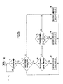
- the lane change assist logic 80 is illustrated in FIG. 5 according to one embodiment.
- Logic 80 begins at step 82 and proceeds to decision step 84 to determine if the vehicle power/ignition is on. If the vehicle power is not on, logic 80 waits for the vehicle power to be turned on before proceeding. Once the vehicle power is turned on, logic 80 proceeds to decision step 86 to determine if a target object is present in the range finder path. If no target object is present in the range finder path, logic 80 proceeds to deactivate both the amber and red LEDs in step 88, and then returns to decision step 86.
- logic 80 proceeds to decision step 90 to process the detected range to the target object. If the measured range is less than or equal to the set range threshold, logic 80 activates the lane occupied red LED and flashes the proceed with caution amber LED in step 92. If the measured range is greater than the set range threshold, logic 80 then proceeds to decision step 94 to determine if the measured range is less than or equal to the range threshold plus constant C (e.g., five feet), which defines an extended warning range. If the measured range is less than or equal to the range threshold plus constant C, logic 80 activates the amber LED and deactivates the red LED in step 96.
- constant C e.g., five feet
- the amber LED serves as a caution warning indicating that an object is not in the adjacent lane, but there is a detected object close to the adjacent lane such that the driver should proceed cautiously. If the measured range is greater than the range threshold plus constant C, logic 80 deactivates both the amber and red LEDs in step 88. Logic 80 continually monitors for the presence of target object(s) and the range to the target object(s), until the vehicle power/ignition is turned off.
- the warning indicator LEDs serve to warn the driver of the host vehicle 10 of the presence of an object in the corresponding adjacent lane.
- the red LED is activated when an object is detected in the adjacent lane side detection zone 34.
- the amber LED is activated to serve as a cautionary warning.
- both LEDs are turned off.
- the warning indicator activation may change from no LEDs to the amber LED, to the red LED, which the driver may easily monitor to assist in maneuvering lane changes.
- the lane change assist system 20 of the present invention quantifies the distance to a detected object that is present in a side detection zone adjacent to the vehicle 10.
- the detection zone may include a region that is visible in a side view mirror to the driver of the vehicle 10 and, hence, is outside of the blind spot region. While the presence of an object in the side detection zone may be viewable to the driver via a mirror, a determination of whether the object is far enough behind the host vehicle to allow the driver to change lanes is provided by the lane change assist system 20 of the present invention.
- the lane change assist system 20 serves as a driver's aid in judging whether the adjacent lane is available for a lane change maneuver.
- the lane change assist system 20 of the present invention advantageously provides a warning indicator to the driver of the host vehicle 10 to assist in maneuvering a lane change.
- the system 20 is cost-effective, easy to install, and easy to use.
- the system 20 is further easily calibratable by a consumer or user and may be used on any of a number of vehicles.
Landscapes
- Engineering & Computer Science (AREA)
- Mechanical Engineering (AREA)
- Human Computer Interaction (AREA)
- Traffic Control Systems (AREA)
- Control Of Driving Devices And Active Controlling Of Vehicle (AREA)
- Radar Systems Or Details Thereof (AREA)
Applications Claiming Priority (1)
| Application Number | Priority Date | Filing Date | Title |
|---|---|---|---|
| US11/135,176 US7501938B2 (en) | 2005-05-23 | 2005-05-23 | Vehicle range-based lane change assist system and method |
Publications (2)
| Publication Number | Publication Date |
|---|---|
| EP1726481A1 true EP1726481A1 (fr) | 2006-11-29 |
| EP1726481B1 EP1726481B1 (fr) | 2010-02-17 |
Family
ID=36919618
Family Applications (1)
| Application Number | Title | Priority Date | Filing Date |
|---|---|---|---|
| EP06076018A Expired - Lifetime EP1726481B1 (fr) | 2005-05-23 | 2006-05-08 | Système et méthode d'assistance au changement de file d'un véhicule basée sur une mesure de distance |
Country Status (4)
| Country | Link |
|---|---|
| US (1) | US7501938B2 (fr) |
| EP (1) | EP1726481B1 (fr) |
| AT (1) | ATE457895T1 (fr) |
| DE (1) | DE602006012246D1 (fr) |
Cited By (5)
| Publication number | Priority date | Publication date | Assignee | Title |
|---|---|---|---|---|
| GB2464914A (en) * | 2008-08-22 | 2010-05-05 | Trw Ltd | A sensor for determining the length of a vehicle upon which the sensor is mounted |
| WO2010064963A1 (fr) * | 2008-12-05 | 2010-06-10 | Volvo Lastvagnar Ab | Système d'aide au changement de voie |
| EP2487454A2 (fr) | 2011-02-14 | 2012-08-15 | Scania CV AB | Estimation de longueur de véhicule |
| US8914181B2 (en) | 2010-12-29 | 2014-12-16 | Siemens S.A.S. | System and method for active lane-changing assistance for a motor vehicle |
| EP4125073A1 (fr) * | 2021-07-29 | 2023-02-01 | KNORR-BREMSE Systeme für Nutzfahrzeuge GmbH | Dispositif et procédé d'assistance d'un véhicule commercial lors du dépassement d'un autre véhicule |
Families Citing this family (16)
| Publication number | Priority date | Publication date | Assignee | Title |
|---|---|---|---|---|
| US7657224B2 (en) * | 2002-05-06 | 2010-02-02 | Syncronation, Inc. | Localized audio networks and associated digital accessories |
| DE102004029369B4 (de) * | 2004-06-17 | 2016-09-15 | Robert Bosch Gmbh | Spurwechselassistent für Kraftfahrzeuge |
| JP5070809B2 (ja) * | 2006-11-10 | 2012-11-14 | アイシン精機株式会社 | 運転支援装置、運転支援方法、及び、プログラム |
| US8170739B2 (en) * | 2008-06-20 | 2012-05-01 | GM Global Technology Operations LLC | Path generation algorithm for automated lane centering and lane changing control system |
| JP5345350B2 (ja) * | 2008-07-30 | 2013-11-20 | 富士重工業株式会社 | 車両の運転支援装置 |
| KR101285006B1 (ko) * | 2009-11-30 | 2013-07-10 | 한국전자통신연구원 | 주변 차량의 운행 정보를 표시하는 자동차 미러 장치 및 그리고 운행 정보 표시 방법 |
| US8890670B2 (en) * | 2011-08-09 | 2014-11-18 | Continental Automotive Systems, Inc. | Smart trailer |
| US9446713B2 (en) * | 2012-09-26 | 2016-09-20 | Magna Electronics Inc. | Trailer angle detection system |
| US9555801B2 (en) * | 2014-03-05 | 2017-01-31 | Denso International America, Inc. | Active steering safety system |
| US9652900B2 (en) * | 2014-03-27 | 2017-05-16 | Jet Optoelectronics Co., Ltd. | Vehicle monitoring system |
| US9211889B1 (en) | 2014-07-29 | 2015-12-15 | Robert Bosch Gmbh | Enhanced blind spot detection for vehicle with trailer |
| US10272838B1 (en) * | 2014-08-20 | 2019-04-30 | Ambarella, Inc. | Reducing lane departure warning false alarms |
| US9493117B2 (en) | 2014-10-08 | 2016-11-15 | Ford Global Technologies, Llc | Vehicle blind spot system operation with trailer tow |
| US9428188B2 (en) | 2014-12-11 | 2016-08-30 | Robert Bosch Gmbh | Lane assist functions for vehicles with a trailer |
| FR3041590B1 (fr) | 2015-09-30 | 2018-08-17 | Renault S.A.S | Systeme de commande de la direction d'un vehicule automobile en cas de collision imminente avec un obstacle |
| USD891953S1 (en) | 2019-03-01 | 2020-08-04 | Kodiak Robotics, Inc. | Sensor assembly |
Citations (3)
| Publication number | Priority date | Publication date | Assignee | Title |
|---|---|---|---|---|
| EP0443185A2 (fr) * | 1990-02-21 | 1991-08-28 | Bayerische Motoren Werke Aktiengesellschaft | Méthode et appareil d'assistance d'un automobiliste qui veut changer de voie |
| DE19725656A1 (de) * | 1996-06-27 | 1998-01-02 | Volkswagen Ag | Sicherheits-Überholsystem |
| EP1607264A1 (fr) * | 2004-06-17 | 2005-12-21 | Robert Bosch GmbH | Dispositif d'assistance au changement de voie pour véhicule automibile |
Family Cites Families (9)
| Publication number | Priority date | Publication date | Assignee | Title |
|---|---|---|---|---|
| US4943796A (en) * | 1989-06-09 | 1990-07-24 | Lee Y C | Rear view mirror mounted reversing distance sensor |
| JP2887039B2 (ja) * | 1993-03-26 | 1999-04-26 | 三菱電機株式会社 | 車両周辺監視装置 |
| DE19514654B4 (de) * | 1994-04-20 | 2009-07-09 | Denso Corporation, Kariya | Kollisionsalarmsystem für ein Kraftfahrzeug |
| US5668675A (en) * | 1995-01-18 | 1997-09-16 | Fredricks; Ronald J. | Opto-electronic aid for alignment of exterior vehicle mirrors to minimize blind spot effects |
| CA2157237A1 (fr) | 1995-08-30 | 1997-03-01 | John W. Patchell | Detecteur de rayonnement thermique |
| US5786772A (en) * | 1996-03-22 | 1998-07-28 | Donnelly Corporation | Vehicle blind spot detection display system |
| US6470273B2 (en) | 2000-11-08 | 2002-10-22 | Milton Halsted | Collision warning system |
| US6753766B2 (en) | 2001-01-15 | 2004-06-22 | 1138037 Ontario Ltd. (“Alirt”) | Detecting device and method of using same |
| US6961006B2 (en) | 2003-04-05 | 2005-11-01 | Delphi Technologies, Inc. | Object detection for a stopped vehicle |
-
2005
- 2005-05-23 US US11/135,176 patent/US7501938B2/en not_active Expired - Lifetime
-
2006
- 2006-05-08 EP EP06076018A patent/EP1726481B1/fr not_active Expired - Lifetime
- 2006-05-08 AT AT06076018T patent/ATE457895T1/de not_active IP Right Cessation
- 2006-05-08 DE DE602006012246T patent/DE602006012246D1/de not_active Expired - Lifetime
Patent Citations (3)
| Publication number | Priority date | Publication date | Assignee | Title |
|---|---|---|---|---|
| EP0443185A2 (fr) * | 1990-02-21 | 1991-08-28 | Bayerische Motoren Werke Aktiengesellschaft | Méthode et appareil d'assistance d'un automobiliste qui veut changer de voie |
| DE19725656A1 (de) * | 1996-06-27 | 1998-01-02 | Volkswagen Ag | Sicherheits-Überholsystem |
| EP1607264A1 (fr) * | 2004-06-17 | 2005-12-21 | Robert Bosch GmbH | Dispositif d'assistance au changement de voie pour véhicule automibile |
Cited By (9)
| Publication number | Priority date | Publication date | Assignee | Title |
|---|---|---|---|---|
| GB2464914A (en) * | 2008-08-22 | 2010-05-05 | Trw Ltd | A sensor for determining the length of a vehicle upon which the sensor is mounted |
| GB2464914B (en) * | 2008-08-22 | 2012-07-25 | Trw Automotive Us Llc | Vehicle length sensors |
| US8576115B2 (en) | 2008-08-22 | 2013-11-05 | Trw Automotive Us Llc | Vehicle length sensors |
| EP2313294A4 (fr) * | 2008-08-22 | 2015-03-11 | Trw Automotive Us Llc | Capteurs de longueur de véhicule |
| WO2010064963A1 (fr) * | 2008-12-05 | 2010-06-10 | Volvo Lastvagnar Ab | Système d'aide au changement de voie |
| US8914181B2 (en) | 2010-12-29 | 2014-12-16 | Siemens S.A.S. | System and method for active lane-changing assistance for a motor vehicle |
| EP2487454A2 (fr) | 2011-02-14 | 2012-08-15 | Scania CV AB | Estimation de longueur de véhicule |
| EP4125073A1 (fr) * | 2021-07-29 | 2023-02-01 | KNORR-BREMSE Systeme für Nutzfahrzeuge GmbH | Dispositif et procédé d'assistance d'un véhicule commercial lors du dépassement d'un autre véhicule |
| WO2023006630A1 (fr) * | 2021-07-29 | 2023-02-02 | Knorr-Bremse Systeme für Nutzfahrzeuge GmbH | Dispositif d'aide au dépassement et procédé d'aide de véhicule utilitaire lors du dépassement d'un autre véhicule |
Also Published As
| Publication number | Publication date |
|---|---|
| US7501938B2 (en) | 2009-03-10 |
| ATE457895T1 (de) | 2010-03-15 |
| EP1726481B1 (fr) | 2010-02-17 |
| US20060261936A1 (en) | 2006-11-23 |
| DE602006012246D1 (de) | 2010-04-01 |
Similar Documents
| Publication | Publication Date | Title |
|---|---|---|
| US7501938B2 (en) | Vehicle range-based lane change assist system and method | |
| US11285875B2 (en) | Method for dynamically calibrating a vehicular trailer angle detection system | |
| US20060006988A1 (en) | Adaptive lighting display for vehicle collision warning | |
| EP2431225B1 (fr) | Procédé de détection de risques automobiles et système d'informations | |
| CN104890671B (zh) | 挂车车道偏离警告系统 | |
| US10106082B2 (en) | System and method for warning of an imminent collision between a towing vehicle and its trailer when reversing | |
| US6193380B1 (en) | Vehicle blind spot mirror | |
| US8350684B2 (en) | Vehicle lane departure warning system having trailer mode and method | |
| US20110010041A1 (en) | Software for an automotive hazardous detection and information system | |
| US20170124881A1 (en) | Blind zone warning for semi-trailer | |
| US20060250224A1 (en) | Means of transport with a three-dimensional distance camera and method for the operation thereof | |
| US20040051659A1 (en) | Vehicular situational awareness system | |
| KR20170000363A (ko) | 차량, 특히 상용 차량을 위한 디스플레이 시스템 | |
| US6961006B2 (en) | Object detection for a stopped vehicle | |
| CN111357038A (zh) | 驾驶员注意力检测方法及装置 | |
| EP1580542A2 (fr) | Détecteur de radiation thermique avec plusieurs capteurs et son procédé d'utilisation | |
| US20100277298A1 (en) | Detection system and method thereof | |
| JP2004529038A (ja) | 車両ミラー | |
| US6581006B2 (en) | System and method for barrier proximity detection | |
| US20210309161A1 (en) | Universal blind spot detection system | |
| US20230365069A1 (en) | Universal blind spot detection system | |
| KR20070012887A (ko) | 측면후방 경고용 사이드뷰와닝미러 모듈 및 제어방법 | |
| KR200407699Y1 (ko) | 졸음운전방지 및 무단 차선이탈 방지장치 | |
| US20070139174A1 (en) | Proximity sensing system | |
| US11718234B1 (en) | Rear view system for a vehicle |
Legal Events
| Date | Code | Title | Description |
|---|---|---|---|
| PUAI | Public reference made under article 153(3) epc to a published international application that has entered the european phase |
Free format text: ORIGINAL CODE: 0009012 |
|
| AK | Designated contracting states |
Kind code of ref document: A1 Designated state(s): AT BE BG CH CY CZ DE DK EE ES FI FR GB GR HU IE IS IT LI LT LU LV MC NL PL PT RO SE SI SK TR |
|
| AX | Request for extension of the european patent |
Extension state: AL BA HR MK YU |
|
| 17P | Request for examination filed |
Effective date: 20070529 |
|
| 17Q | First examination report despatched |
Effective date: 20070704 |
|
| AKX | Designation fees paid |
Designated state(s): AT BE BG CH CY CZ DE DK EE ES FI FR GB GR HU IE IS IT LI LT LU LV MC NL PL PT RO SE SI SK TR |
|
| GRAP | Despatch of communication of intention to grant a patent |
Free format text: ORIGINAL CODE: EPIDOSNIGR1 |
|
| GRAS | Grant fee paid |
Free format text: ORIGINAL CODE: EPIDOSNIGR3 |
|
| GRAA | (expected) grant |
Free format text: ORIGINAL CODE: 0009210 |
|
| AK | Designated contracting states |
Kind code of ref document: B1 Designated state(s): AT BE BG CH CY CZ DE DK EE ES FI FR GB GR HU IE IS IT LI LT LU LV MC NL PL PT RO SE SI SK TR |
|
| REG | Reference to a national code |
Ref country code: GB Ref legal event code: FG4D |
|
| REG | Reference to a national code |
Ref country code: CH Ref legal event code: EP |
|
| REG | Reference to a national code |
Ref country code: IE Ref legal event code: FG4D |
|
| REF | Corresponds to: |
Ref document number: 602006012246 Country of ref document: DE Date of ref document: 20100401 Kind code of ref document: P |
|
| REG | Reference to a national code |
Ref country code: NL Ref legal event code: VDEP Effective date: 20100217 |
|
| LTIE | Lt: invalidation of european patent or patent extension |
Effective date: 20100217 |
|
| PG25 | Lapsed in a contracting state [announced via postgrant information from national office to epo] |
Ref country code: ES Free format text: LAPSE BECAUSE OF FAILURE TO SUBMIT A TRANSLATION OF THE DESCRIPTION OR TO PAY THE FEE WITHIN THE PRESCRIBED TIME-LIMIT Effective date: 20100528 Ref country code: LT Free format text: LAPSE BECAUSE OF FAILURE TO SUBMIT A TRANSLATION OF THE DESCRIPTION OR TO PAY THE FEE WITHIN THE PRESCRIBED TIME-LIMIT Effective date: 20100217 Ref country code: IS Free format text: LAPSE BECAUSE OF FAILURE TO SUBMIT A TRANSLATION OF THE DESCRIPTION OR TO PAY THE FEE WITHIN THE PRESCRIBED TIME-LIMIT Effective date: 20100617 Ref country code: PT Free format text: LAPSE BECAUSE OF FAILURE TO SUBMIT A TRANSLATION OF THE DESCRIPTION OR TO PAY THE FEE WITHIN THE PRESCRIBED TIME-LIMIT Effective date: 20100617 |
|
| PG25 | Lapsed in a contracting state [announced via postgrant information from national office to epo] |
Ref country code: SI Free format text: LAPSE BECAUSE OF FAILURE TO SUBMIT A TRANSLATION OF THE DESCRIPTION OR TO PAY THE FEE WITHIN THE PRESCRIBED TIME-LIMIT Effective date: 20100217 Ref country code: PL Free format text: LAPSE BECAUSE OF FAILURE TO SUBMIT A TRANSLATION OF THE DESCRIPTION OR TO PAY THE FEE WITHIN THE PRESCRIBED TIME-LIMIT Effective date: 20100217 Ref country code: LV Free format text: LAPSE BECAUSE OF FAILURE TO SUBMIT A TRANSLATION OF THE DESCRIPTION OR TO PAY THE FEE WITHIN THE PRESCRIBED TIME-LIMIT Effective date: 20100217 Ref country code: FI Free format text: LAPSE BECAUSE OF FAILURE TO SUBMIT A TRANSLATION OF THE DESCRIPTION OR TO PAY THE FEE WITHIN THE PRESCRIBED TIME-LIMIT Effective date: 20100217 Ref country code: AT Free format text: LAPSE BECAUSE OF FAILURE TO SUBMIT A TRANSLATION OF THE DESCRIPTION OR TO PAY THE FEE WITHIN THE PRESCRIBED TIME-LIMIT Effective date: 20100217 |
|
| PG25 | Lapsed in a contracting state [announced via postgrant information from national office to epo] |
Ref country code: GR Free format text: LAPSE BECAUSE OF FAILURE TO SUBMIT A TRANSLATION OF THE DESCRIPTION OR TO PAY THE FEE WITHIN THE PRESCRIBED TIME-LIMIT Effective date: 20100518 Ref country code: SE Free format text: LAPSE BECAUSE OF FAILURE TO SUBMIT A TRANSLATION OF THE DESCRIPTION OR TO PAY THE FEE WITHIN THE PRESCRIBED TIME-LIMIT Effective date: 20100217 Ref country code: RO Free format text: LAPSE BECAUSE OF FAILURE TO SUBMIT A TRANSLATION OF THE DESCRIPTION OR TO PAY THE FEE WITHIN THE PRESCRIBED TIME-LIMIT Effective date: 20100217 Ref country code: NL Free format text: LAPSE BECAUSE OF FAILURE TO SUBMIT A TRANSLATION OF THE DESCRIPTION OR TO PAY THE FEE WITHIN THE PRESCRIBED TIME-LIMIT Effective date: 20100217 Ref country code: EE Free format text: LAPSE BECAUSE OF FAILURE TO SUBMIT A TRANSLATION OF THE DESCRIPTION OR TO PAY THE FEE WITHIN THE PRESCRIBED TIME-LIMIT Effective date: 20100217 Ref country code: CY Free format text: LAPSE BECAUSE OF FAILURE TO SUBMIT A TRANSLATION OF THE DESCRIPTION OR TO PAY THE FEE WITHIN THE PRESCRIBED TIME-LIMIT Effective date: 20100217 Ref country code: BE Free format text: LAPSE BECAUSE OF FAILURE TO SUBMIT A TRANSLATION OF THE DESCRIPTION OR TO PAY THE FEE WITHIN THE PRESCRIBED TIME-LIMIT Effective date: 20100217 |
|
| PG25 | Lapsed in a contracting state [announced via postgrant information from national office to epo] |
Ref country code: SK Free format text: LAPSE BECAUSE OF FAILURE TO SUBMIT A TRANSLATION OF THE DESCRIPTION OR TO PAY THE FEE WITHIN THE PRESCRIBED TIME-LIMIT Effective date: 20100217 Ref country code: BG Free format text: LAPSE BECAUSE OF FAILURE TO SUBMIT A TRANSLATION OF THE DESCRIPTION OR TO PAY THE FEE WITHIN THE PRESCRIBED TIME-LIMIT Effective date: 20100517 Ref country code: CZ Free format text: LAPSE BECAUSE OF FAILURE TO SUBMIT A TRANSLATION OF THE DESCRIPTION OR TO PAY THE FEE WITHIN THE PRESCRIBED TIME-LIMIT Effective date: 20100217 |
|
| PLBE | No opposition filed within time limit |
Free format text: ORIGINAL CODE: 0009261 |
|
| STAA | Information on the status of an ep patent application or granted ep patent |
Free format text: STATUS: NO OPPOSITION FILED WITHIN TIME LIMIT |
|
| PG25 | Lapsed in a contracting state [announced via postgrant information from national office to epo] |
Ref country code: MC Free format text: LAPSE BECAUSE OF NON-PAYMENT OF DUE FEES Effective date: 20100531 |
|
| REG | Reference to a national code |
Ref country code: CH Ref legal event code: PL |
|
| 26N | No opposition filed |
Effective date: 20101118 |
|
| GBPC | Gb: european patent ceased through non-payment of renewal fee |
Effective date: 20100517 |
|
| PG25 | Lapsed in a contracting state [announced via postgrant information from national office to epo] |
Ref country code: DK Free format text: LAPSE BECAUSE OF FAILURE TO SUBMIT A TRANSLATION OF THE DESCRIPTION OR TO PAY THE FEE WITHIN THE PRESCRIBED TIME-LIMIT Effective date: 20100217 |
|
| REG | Reference to a national code |
Ref country code: FR Ref legal event code: ST Effective date: 20110131 |
|
| PG25 | Lapsed in a contracting state [announced via postgrant information from national office to epo] |
Ref country code: CH Free format text: LAPSE BECAUSE OF NON-PAYMENT OF DUE FEES Effective date: 20100531 Ref country code: LI Free format text: LAPSE BECAUSE OF NON-PAYMENT OF DUE FEES Effective date: 20100531 |
|
| PG25 | Lapsed in a contracting state [announced via postgrant information from national office to epo] |
Ref country code: IT Free format text: LAPSE BECAUSE OF FAILURE TO SUBMIT A TRANSLATION OF THE DESCRIPTION OR TO PAY THE FEE WITHIN THE PRESCRIBED TIME-LIMIT Effective date: 20100217 |
|
| PG25 | Lapsed in a contracting state [announced via postgrant information from national office to epo] |
Ref country code: IE Free format text: LAPSE BECAUSE OF NON-PAYMENT OF DUE FEES Effective date: 20100508 |
|
| PG25 | Lapsed in a contracting state [announced via postgrant information from national office to epo] |
Ref country code: FR Free format text: LAPSE BECAUSE OF NON-PAYMENT OF DUE FEES Effective date: 20100531 |
|
| PG25 | Lapsed in a contracting state [announced via postgrant information from national office to epo] |
Ref country code: GB Free format text: LAPSE BECAUSE OF NON-PAYMENT OF DUE FEES Effective date: 20100517 |
|
| PG25 | Lapsed in a contracting state [announced via postgrant information from national office to epo] |
Ref country code: HU Free format text: LAPSE BECAUSE OF FAILURE TO SUBMIT A TRANSLATION OF THE DESCRIPTION OR TO PAY THE FEE WITHIN THE PRESCRIBED TIME-LIMIT Effective date: 20100818 Ref country code: LU Free format text: LAPSE BECAUSE OF NON-PAYMENT OF DUE FEES Effective date: 20100508 |
|
| PG25 | Lapsed in a contracting state [announced via postgrant information from national office to epo] |
Ref country code: TR Free format text: LAPSE BECAUSE OF FAILURE TO SUBMIT A TRANSLATION OF THE DESCRIPTION OR TO PAY THE FEE WITHIN THE PRESCRIBED TIME-LIMIT Effective date: 20100217 |
|
| REG | Reference to a national code |
Ref country code: DE Ref legal event code: R081 Ref document number: 602006012246 Country of ref document: DE Owner name: APTIV TECHNOLOGIES LIMITED, BB Free format text: FORMER OWNER: DELPHI TECHNOLOGIES, INC., TROY, MICH., US |
|
| P01 | Opt-out of the competence of the unified patent court (upc) registered |
Effective date: 20230425 |
|
| REG | Reference to a national code |
Ref country code: DE Ref legal event code: R081 Ref document number: 602006012246 Country of ref document: DE Owner name: APTIV TECHNOLOGIES AG, CH Free format text: FORMER OWNER: APTIV TECHNOLOGIES LIMITED, ST. MICHAEL, BB |
|
| PGFP | Annual fee paid to national office [announced via postgrant information from national office to epo] |
Ref country code: DE Payment date: 20250422 Year of fee payment: 20 |