EP1726577B1 - Verfahren zur katalytischen umsetzung unter einsatz eines mikroreaktors - Google Patents
Verfahren zur katalytischen umsetzung unter einsatz eines mikroreaktors Download PDFInfo
- Publication number
- EP1726577B1 EP1726577B1 EP05704332A EP05704332A EP1726577B1 EP 1726577 B1 EP1726577 B1 EP 1726577B1 EP 05704332 A EP05704332 A EP 05704332A EP 05704332 A EP05704332 A EP 05704332A EP 1726577 B1 EP1726577 B1 EP 1726577B1
- Authority
- EP
- European Patent Office
- Prior art keywords
- micro
- channel
- catalyst
- reaction
- reactor
- Prior art date
- Legal status (The legal status is an assumption and is not a legal conclusion. Google has not performed a legal analysis and makes no representation as to the accuracy of the status listed.)
- Expired - Lifetime
Links
Images




Classifications
-
- C—CHEMISTRY; METALLURGY
- C07—ORGANIC CHEMISTRY
- C07C—ACYCLIC OR CARBOCYCLIC COMPOUNDS
- C07C5/00—Preparation of hydrocarbons from hydrocarbons containing the same number of carbon atoms
- C07C5/02—Preparation of hydrocarbons from hydrocarbons containing the same number of carbon atoms by hydrogenation
- C07C5/03—Preparation of hydrocarbons from hydrocarbons containing the same number of carbon atoms by hydrogenation of non-aromatic carbon-to-carbon double bonds
-
- B—PERFORMING OPERATIONS; TRANSPORTING
- B01—PHYSICAL OR CHEMICAL PROCESSES OR APPARATUS IN GENERAL
- B01J—CHEMICAL OR PHYSICAL PROCESSES, e.g. CATALYSIS OR COLLOID CHEMISTRY; THEIR RELEVANT APPARATUS
- B01J19/00—Chemical, physical or physico-chemical processes in general; Their relevant apparatus
- B01J19/0093—Microreactors, e.g. miniaturised or microfabricated reactors
-
- B—PERFORMING OPERATIONS; TRANSPORTING
- B01—PHYSICAL OR CHEMICAL PROCESSES OR APPARATUS IN GENERAL
- B01J—CHEMICAL OR PHYSICAL PROCESSES, e.g. CATALYSIS OR COLLOID CHEMISTRY; THEIR RELEVANT APPARATUS
- B01J23/00—Catalysts comprising metals or metal oxides or hydroxides, not provided for in group B01J21/00
- B01J23/38—Catalysts comprising metals or metal oxides or hydroxides, not provided for in group B01J21/00 of noble metals
- B01J23/40—Catalysts comprising metals or metal oxides or hydroxides, not provided for in group B01J21/00 of noble metals of the platinum group metals
- B01J23/44—Palladium
-
- B—PERFORMING OPERATIONS; TRANSPORTING
- B01—PHYSICAL OR CHEMICAL PROCESSES OR APPARATUS IN GENERAL
- B01J—CHEMICAL OR PHYSICAL PROCESSES, e.g. CATALYSIS OR COLLOID CHEMISTRY; THEIR RELEVANT APPARATUS
- B01J31/00—Catalysts comprising hydrides, coordination complexes or organic compounds
- B01J31/16—Catalysts comprising hydrides, coordination complexes or organic compounds containing coordination complexes
- B01J31/1616—Coordination complexes, e.g. organometallic complexes, immobilised on an inorganic support, e.g. ship-in-a-bottle type catalysts
- B01J31/1625—Coordination complexes, e.g. organometallic complexes, immobilised on an inorganic support, e.g. ship-in-a-bottle type catalysts immobilised by covalent linkages, i.e. pendant complexes with optional linking groups
- B01J31/1633—Coordination complexes, e.g. organometallic complexes, immobilised on an inorganic support, e.g. ship-in-a-bottle type catalysts immobilised by covalent linkages, i.e. pendant complexes with optional linking groups covalent linkages via silicon containing groups
-
- B—PERFORMING OPERATIONS; TRANSPORTING
- B01—PHYSICAL OR CHEMICAL PROCESSES OR APPARATUS IN GENERAL
- B01J—CHEMICAL OR PHYSICAL PROCESSES, e.g. CATALYSIS OR COLLOID CHEMISTRY; THEIR RELEVANT APPARATUS
- B01J37/00—Processes, in general, for preparing catalysts; Processes, in general, for activation of catalysts
- B01J37/02—Impregnation, coating or precipitation
- B01J37/0215—Coating
- B01J37/0219—Coating the coating containing organic compounds
-
- C—CHEMISTRY; METALLURGY
- C07—ORGANIC CHEMISTRY
- C07C—ACYCLIC OR CARBOCYCLIC COMPOUNDS
- C07C209/00—Preparation of compounds containing amino groups bound to a carbon skeleton
- C07C209/30—Preparation of compounds containing amino groups bound to a carbon skeleton by reduction of nitrogen-to-oxygen or nitrogen-to-nitrogen bonds
- C07C209/32—Preparation of compounds containing amino groups bound to a carbon skeleton by reduction of nitrogen-to-oxygen or nitrogen-to-nitrogen bonds by reduction of nitro groups
- C07C209/36—Preparation of compounds containing amino groups bound to a carbon skeleton by reduction of nitrogen-to-oxygen or nitrogen-to-nitrogen bonds by reduction of nitro groups by reduction of nitro groups bound to carbon atoms of six-membered aromatic rings in presence of hydrogen-containing gases and a catalyst
-
- C—CHEMISTRY; METALLURGY
- C07—ORGANIC CHEMISTRY
- C07C—ACYCLIC OR CARBOCYCLIC COMPOUNDS
- C07C29/00—Preparation of compounds having hydroxy or O-metal groups bound to a carbon atom not belonging to a six-membered aromatic ring
- C07C29/17—Preparation of compounds having hydroxy or O-metal groups bound to a carbon atom not belonging to a six-membered aromatic ring by hydrogenation of carbon-to-carbon double or triple bonds
- C07C29/175—Preparation of compounds having hydroxy or O-metal groups bound to a carbon atom not belonging to a six-membered aromatic ring by hydrogenation of carbon-to-carbon double or triple bonds with simultaneous reduction of an oxo group
-
- C—CHEMISTRY; METALLURGY
- C07—ORGANIC CHEMISTRY
- C07C—ACYCLIC OR CARBOCYCLIC COMPOUNDS
- C07C45/00—Preparation of compounds having >C = O groups bound only to carbon or hydrogen atoms; Preparation of chelates of such compounds
- C07C45/61—Preparation of compounds having >C = O groups bound only to carbon or hydrogen atoms; Preparation of chelates of such compounds by reactions not involving the formation of >C = O groups
- C07C45/62—Preparation of compounds having >C = O groups bound only to carbon or hydrogen atoms; Preparation of chelates of such compounds by reactions not involving the formation of >C = O groups by hydrogenation of carbon-to-carbon double or triple bonds
-
- C—CHEMISTRY; METALLURGY
- C07—ORGANIC CHEMISTRY
- C07C—ACYCLIC OR CARBOCYCLIC COMPOUNDS
- C07C5/00—Preparation of hydrocarbons from hydrocarbons containing the same number of carbon atoms
- C07C5/02—Preparation of hydrocarbons from hydrocarbons containing the same number of carbon atoms by hydrogenation
- C07C5/08—Preparation of hydrocarbons from hydrocarbons containing the same number of carbon atoms by hydrogenation of carbon-to-carbon triple bonds
-
- B—PERFORMING OPERATIONS; TRANSPORTING
- B01—PHYSICAL OR CHEMICAL PROCESSES OR APPARATUS IN GENERAL
- B01J—CHEMICAL OR PHYSICAL PROCESSES, e.g. CATALYSIS OR COLLOID CHEMISTRY; THEIR RELEVANT APPARATUS
- B01J2219/00—Chemical, physical or physico-chemical processes in general; Their relevant apparatus
- B01J2219/00781—Aspects relating to microreactors
- B01J2219/00819—Materials of construction
- B01J2219/00831—Glass
-
- B—PERFORMING OPERATIONS; TRANSPORTING
- B01—PHYSICAL OR CHEMICAL PROCESSES OR APPARATUS IN GENERAL
- B01J—CHEMICAL OR PHYSICAL PROCESSES, e.g. CATALYSIS OR COLLOID CHEMISTRY; THEIR RELEVANT APPARATUS
- B01J2219/00—Chemical, physical or physico-chemical processes in general; Their relevant apparatus
- B01J2219/00781—Aspects relating to microreactors
- B01J2219/00819—Materials of construction
- B01J2219/00835—Comprising catalytically active material
-
- B—PERFORMING OPERATIONS; TRANSPORTING
- B01—PHYSICAL OR CHEMICAL PROCESSES OR APPARATUS IN GENERAL
- B01J—CHEMICAL OR PHYSICAL PROCESSES, e.g. CATALYSIS OR COLLOID CHEMISTRY; THEIR RELEVANT APPARATUS
- B01J2231/00—Catalytic reactions performed with catalysts classified in B01J31/00
- B01J2231/60—Reduction reactions, e.g. hydrogenation
- B01J2231/64—Reductions in general of organic substrates, e.g. hydride reductions or hydrogenations
- B01J2231/641—Hydrogenation of organic substrates, i.e. H2 or H-transfer hydrogenations, e.g. Fischer-Tropsch processes
-
- B—PERFORMING OPERATIONS; TRANSPORTING
- B01—PHYSICAL OR CHEMICAL PROCESSES OR APPARATUS IN GENERAL
- B01J—CHEMICAL OR PHYSICAL PROCESSES, e.g. CATALYSIS OR COLLOID CHEMISTRY; THEIR RELEVANT APPARATUS
- B01J2231/00—Catalytic reactions performed with catalysts classified in B01J31/00
- B01J2231/60—Reduction reactions, e.g. hydrogenation
- B01J2231/64—Reductions in general of organic substrates, e.g. hydride reductions or hydrogenations
- B01J2231/641—Hydrogenation of organic substrates, i.e. H2 or H-transfer hydrogenations, e.g. Fischer-Tropsch processes
- B01J2231/643—Hydrogenation of organic substrates, i.e. H2 or H-transfer hydrogenations, e.g. Fischer-Tropsch processes of R2C=O or R2C=NR (R= C, H)
-
- B—PERFORMING OPERATIONS; TRANSPORTING
- B01—PHYSICAL OR CHEMICAL PROCESSES OR APPARATUS IN GENERAL
- B01J—CHEMICAL OR PHYSICAL PROCESSES, e.g. CATALYSIS OR COLLOID CHEMISTRY; THEIR RELEVANT APPARATUS
- B01J2231/00—Catalytic reactions performed with catalysts classified in B01J31/00
- B01J2231/60—Reduction reactions, e.g. hydrogenation
- B01J2231/64—Reductions in general of organic substrates, e.g. hydride reductions or hydrogenations
- B01J2231/641—Hydrogenation of organic substrates, i.e. H2 or H-transfer hydrogenations, e.g. Fischer-Tropsch processes
- B01J2231/645—Hydrogenation of organic substrates, i.e. H2 or H-transfer hydrogenations, e.g. Fischer-Tropsch processes of C=C or C-C triple bonds
-
- B—PERFORMING OPERATIONS; TRANSPORTING
- B01—PHYSICAL OR CHEMICAL PROCESSES OR APPARATUS IN GENERAL
- B01J—CHEMICAL OR PHYSICAL PROCESSES, e.g. CATALYSIS OR COLLOID CHEMISTRY; THEIR RELEVANT APPARATUS
- B01J2531/00—Additional information regarding catalytic systems classified in B01J31/00
- B01J2531/60—Complexes comprising metals of Group VI (VIA or VIB) as the central metal
- B01J2531/62—Chromium
-
- B—PERFORMING OPERATIONS; TRANSPORTING
- B01—PHYSICAL OR CHEMICAL PROCESSES OR APPARATUS IN GENERAL
- B01J—CHEMICAL OR PHYSICAL PROCESSES, e.g. CATALYSIS OR COLLOID CHEMISTRY; THEIR RELEVANT APPARATUS
- B01J2531/00—Additional information regarding catalytic systems classified in B01J31/00
- B01J2531/60—Complexes comprising metals of Group VI (VIA or VIB) as the central metal
- B01J2531/64—Molybdenum
-
- B—PERFORMING OPERATIONS; TRANSPORTING
- B01—PHYSICAL OR CHEMICAL PROCESSES OR APPARATUS IN GENERAL
- B01J—CHEMICAL OR PHYSICAL PROCESSES, e.g. CATALYSIS OR COLLOID CHEMISTRY; THEIR RELEVANT APPARATUS
- B01J2531/00—Additional information regarding catalytic systems classified in B01J31/00
- B01J2531/60—Complexes comprising metals of Group VI (VIA or VIB) as the central metal
- B01J2531/66—Tungsten
-
- B—PERFORMING OPERATIONS; TRANSPORTING
- B01—PHYSICAL OR CHEMICAL PROCESSES OR APPARATUS IN GENERAL
- B01J—CHEMICAL OR PHYSICAL PROCESSES, e.g. CATALYSIS OR COLLOID CHEMISTRY; THEIR RELEVANT APPARATUS
- B01J2531/00—Additional information regarding catalytic systems classified in B01J31/00
- B01J2531/70—Complexes comprising metals of Group VII (VIIB) as the central metal
- B01J2531/72—Manganese
-
- B—PERFORMING OPERATIONS; TRANSPORTING
- B01—PHYSICAL OR CHEMICAL PROCESSES OR APPARATUS IN GENERAL
- B01J—CHEMICAL OR PHYSICAL PROCESSES, e.g. CATALYSIS OR COLLOID CHEMISTRY; THEIR RELEVANT APPARATUS
- B01J2531/00—Additional information regarding catalytic systems classified in B01J31/00
- B01J2531/80—Complexes comprising metals of Group VIII as the central metal
- B01J2531/82—Metals of the platinum group
- B01J2531/821—Ruthenium
-
- B—PERFORMING OPERATIONS; TRANSPORTING
- B01—PHYSICAL OR CHEMICAL PROCESSES OR APPARATUS IN GENERAL
- B01J—CHEMICAL OR PHYSICAL PROCESSES, e.g. CATALYSIS OR COLLOID CHEMISTRY; THEIR RELEVANT APPARATUS
- B01J2531/00—Additional information regarding catalytic systems classified in B01J31/00
- B01J2531/80—Complexes comprising metals of Group VIII as the central metal
- B01J2531/82—Metals of the platinum group
- B01J2531/822—Rhodium
-
- B—PERFORMING OPERATIONS; TRANSPORTING
- B01—PHYSICAL OR CHEMICAL PROCESSES OR APPARATUS IN GENERAL
- B01J—CHEMICAL OR PHYSICAL PROCESSES, e.g. CATALYSIS OR COLLOID CHEMISTRY; THEIR RELEVANT APPARATUS
- B01J2531/00—Additional information regarding catalytic systems classified in B01J31/00
- B01J2531/80—Complexes comprising metals of Group VIII as the central metal
- B01J2531/82—Metals of the platinum group
- B01J2531/824—Palladium
-
- B—PERFORMING OPERATIONS; TRANSPORTING
- B01—PHYSICAL OR CHEMICAL PROCESSES OR APPARATUS IN GENERAL
- B01J—CHEMICAL OR PHYSICAL PROCESSES, e.g. CATALYSIS OR COLLOID CHEMISTRY; THEIR RELEVANT APPARATUS
- B01J2531/00—Additional information regarding catalytic systems classified in B01J31/00
- B01J2531/80—Complexes comprising metals of Group VIII as the central metal
- B01J2531/82—Metals of the platinum group
- B01J2531/825—Osmium
-
- B—PERFORMING OPERATIONS; TRANSPORTING
- B01—PHYSICAL OR CHEMICAL PROCESSES OR APPARATUS IN GENERAL
- B01J—CHEMICAL OR PHYSICAL PROCESSES, e.g. CATALYSIS OR COLLOID CHEMISTRY; THEIR RELEVANT APPARATUS
- B01J2531/00—Additional information regarding catalytic systems classified in B01J31/00
- B01J2531/80—Complexes comprising metals of Group VIII as the central metal
- B01J2531/82—Metals of the platinum group
- B01J2531/827—Iridium
-
- C—CHEMISTRY; METALLURGY
- C07—ORGANIC CHEMISTRY
- C07C—ACYCLIC OR CARBOCYCLIC COMPOUNDS
- C07C2601/00—Systems containing only non-condensed rings
- C07C2601/12—Systems containing only non-condensed rings with a six-membered ring
- C07C2601/14—The ring being saturated
-
- Y—GENERAL TAGGING OF NEW TECHNOLOGICAL DEVELOPMENTS; GENERAL TAGGING OF CROSS-SECTIONAL TECHNOLOGIES SPANNING OVER SEVERAL SECTIONS OF THE IPC; TECHNICAL SUBJECTS COVERED BY FORMER USPC CROSS-REFERENCE ART COLLECTIONS [XRACs] AND DIGESTS
- Y02—TECHNOLOGIES OR APPLICATIONS FOR MITIGATION OR ADAPTATION AGAINST CLIMATE CHANGE
- Y02P—CLIMATE CHANGE MITIGATION TECHNOLOGIES IN THE PRODUCTION OR PROCESSING OF GOODS
- Y02P20/00—Technologies relating to chemical industry
- Y02P20/50—Improvements relating to the production of bulk chemicals
Definitions
- the present invention relates to a method of catalytic reaction using a micro-reactor.
- catalytic hydrogenation reaction using a heterogeneous catalyst so-called catalytic reductive reaction is one of the most important processes in chemical industry, and is widely utilized for hydrogenation of aromatic nitro compounds and unsaturated bonds or de-benzylation reaction by hydrogenation, but there are often deterioration of yield and slow-down of reaction proceedings. Since these problems are solved by increasing the contact area between each phase, the catalytic surface (solid phase) - solution (liquid phase) - hydrogen gas (gas phase) (hereinafter, to be called a solid - liquid - gas phase reaction or three phase catalytic reduction reaction), such techniques have been tried as vigorous stirring or blowing in hydrogen gas as fine bubbles. In the catalytic hydrogenation reaction in an ordinary reactor (hereinafter, properly called a flask reaction), ignition or explosion may be possible since hydrogen gas, solvent vapor, and highly active metal catalysts co-exist is the system.
- a micro-reactor is a generic term for a micro-reactor having micro-channels of the size of several to several hundred ⁇ m in an inactive material such as glass. Since a micro-reactor is small, strict temperature control is easily possible. Therefore, synthetic reactions using a micro-reactor have such merits as (1) high reaction efficiency on interfaces, (2) efficient mixing by molecular diffusion, and (3) easy temperature control, owing to large surface area per unit volume.
- a hydrogenation reaction using a micro-reactor is described, which is a two-phase reaction of gas - solid with a catalyst immobilized on the inner wall of a micro-channel.
- a slug flow and a pipe flow are known.
- Fig. 8 is a cross-sectional view diagrammatically illustrating (a) slug flow and (b) pipe flow in a conventional micro-channel.
- a slug flow is the state of liquid 52 and gas 53 alternatively passing through a micro-channel 51 provided on a glass substrate.
- Fig. 8(a) a slug flow is the state of liquid 52 and gas 53 alternatively passing through a micro-channel 51 provided on a glass substrate.
- gas 53 passes in the center part of a micro-channel 51, and liquid 52 passes between the gas 53 and the inner wall 51a of a micro-channel.
- liquid 52 passes between the gas 53 and the inner wall 51a of a micro-channel.
- Which type, a slug or a pipe flow, the fluid in a micro-channel takes can be controlled by adjusting the flow rates of liquid 52 and gas 53 passing through a micro-channel 51.
- Carbon monoxide insertion reaction is reported as a reaction in a flask (refer to Reference 6.), but there is no reference for carbon monoxide insertion reaction using a micro-channel reactor.
- WO99/22857 discloses a method for performing three-phase catalytic reactions in a microreactor.
- one aspect of the present invention provides a method of catalytic reaction using a micro-reactor according to claim 1.
- hydrogenation reaction or hydrocracking reaction can be conducted by three phase catalytic reaction in short time at high yield.
- the metal catalyst is preferably palladium.
- the metal complex catalyst is preferably a palladium complex catalyst.
- the metal catalyst may be either chromium, manganese, iron, cobalt, nickel, copper, molybdenum, ruthenium, rhodium, tungsten, osmium, iridium, or platinum.
- the metal complex catalyst may be a metal complex catalyst of either chromium, manganese, iron, cobalt, nickel, copper, molybdenum, ruthenium, rhodium, tungsten, osmium, iridium, or platinum.
- the surface of the inner wall of a channel preferably has silanol groups, and the spacers are covalent bonded with silanol groups by Si-O-Si bond.
- the groups on a polymer surface is preferably epoxide groups, and the groups in the spacers are modified with functional groups bondable with epoxide groups.
- three phase catalytic reductive reaction can be conducted in short time by supporting a catalyst, particularly a metal or a metal complex catalyst as a solid phase on the inner wall of a micro-channel of a micro-reactor. Further, since such complicated operation as separation of products and a catalyst and recovery of a catalyst is unnecessary, continuous operation of long time is possible.
- FIG. 1 diagrammatically illustrates the makeup of a micro-reactor used in the embodiments of the present invention, and (a) is a plan view and (b) is a partial cross-sectional view along a line Y - Y.
- a micro-reactor 1 is provided with substrates 2 and 3 made of an inactive material such as glass, micro-channels 4 provided snakingly on the substrate 2, a catalyst 5 immobilized, that is, supported on the surface of the micro-channel 4, a solution 7 in which reactants are dissolved supplied via a liquid-feeding pump 6, a gas cylinder 9a supplying a gas 9 supplied via a gas valve 8, and a vessel for recovery 10.
- hydrogen or carbon monoxide (CO) is mentioned as the gas supplied via a gas valve 8.
- explanation will be made with hydrogen as the gas 9.
- the examples which mention carbon monoxide (CO) as the gas 9 do not fall within the scope of the claimed invention.
- the micro-channel 4 is made with its cross-section carved in oblong or semi-circular shape by grinding with a tool such as an end mill or by etching with a mask.
- the substrate 2 on which the micro-channel 4 is provided is tightly fixed with a substrate 3 of the same size on which a micro-channel is not carved face to face so that the solution 7 and hydrogen 9 do not leach.
- the substrate 2 on which a micro-channel 4 is carved and the substrate 3 facing thereto may be of a material not corrosive by reactants or organic solvents, and may be of such a material as resins and metals in addition to glass.
- the solution 7 is connected with the liquid-feeding pump 6 and Teflon (registered trademark) tube, and its supply rate is controlled by a flow rate adjuster using a syringe pump or others (not shown).
- the hydrogen gas cylinder 9a is connected with the gas valve 8 and Teflon (registered trademark) tube, and its supply rate is controlled by a flow rate adjuster using a mass flow controller or others (not shown).
- the solution 7 and hydrogen 9 are combined at an inlet part 4a of the micro-channel.
- the vessel for recovery 10 is connected to an outlet part 4b of the micro-channel with Teflon (registered trademark) tube or others.
- Fig. 2 is a cross-sectional view illustrating the states of a solution and hydrogen passing through a micro-channel of the present invention.
- hydrogen 14 passing through a micro-channel passes through a center part of the micro-channel 4.
- the solution 12 passing through a micro-channel passes between hydrogen 14 passes through a micro-channel and a catalyst supported on an inner wall 4c of the micro-channel in a so-called pipe flow state, from the inlet part 4a to the outlet part 4b.
- the flow rates of the solution 7 and hydrogen 9 are controlled to be in the above-mentioned pipe flow state by the flow rate adjusters not shown of the solution 7 and hydrogen 9.
- a liquid reactant 7 from a liquid-feeding pump 6 and hydrogen 9 from a gas valve 8 are injected into a micro-channel 4 so to be in a pipe flow. While passing through the micro-channel 4, the reactant solution 12 and hydrogen 14 passing through the micro-channel are reacted by the action of a catalyst 5 supported on its inner wall 4c. The reaction mixture containing the object formed by reaction is collected into a vessel for recovery 10, and taken out upon necessity.
- a metal or a metal complex catalyst of either of palladium (Pd), Chromium (Cr), manganese (Mn), iron (Fe), cobalt (Co), nickel (Ni), copper (Cu), molybdenum (Mo), ruthenium (Ru), rhodium (Rh), tungsten (W), osmium (Os), iridium (Ir), or platinum (Pt) may be used.
- the above-mentioned catalyst 5 is preferably a polymer-inclusion catalyst (hereinafter to be called a PI catalyst) with the above-mentioned metal catalyst or metal complex catalyst immobilized in a polymer (Refer to the above-mentioned Reference 5.).
- a PI catalyst polymer-inclusion catalyst
- metal catalyst or metal complex catalyst immobilized in a polymer
- one end of a spacer 4d of the PI catalyst 5 mentioned below is modified with a trialcoxysilane structure, and bonded to a silanol group on the glass surface as the inner wall 4c of the micro-channel.
- the other end of the spacer 4d can be bonded directly to, for example, an epoxy group on the polymer surface of the PI catalyst 5 by modifying it with a functional group such as amino group and others.
- bonding is similarly possible to the above-mentioned epoxy group by modifying the resin surface with a functional group such as amino group and others. Since thereby the PI catalyst can be firmly supported on the inner wall 4c of a micro-channel, it does not dissociate from the inner wall 4c of a micro-channel, and can be used repeatedly.
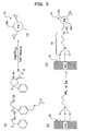
- Fig. 3 is a view diagrammatically illustrating the reaction to support a PI catalyst 5 in a micro-channel 4.
- the catalyst is micro-encapsulated by dissolving a polymer in an appropriate solvent and further adding a substance containing the catalyst (See Fig. 3(a) .).
- the metal or the metal complex is present not only inside the capsule but also on or near the surface.
- Fig. 3(c) diagrammatically illustrates the inner wall of a micro-channel on which is supported the thus obtained PI catalyst 5, and 4d illustrates the spacer of the surface group of a micro-channel and the catalyst.
- hydrogenation reaction can be conducted in short time by three phase catalytic reaction in so-called pipe flow state in which the solution 7 containing reactants is flown contacting the inner wall 4c of the micro-channel on which the catalyst is supported, and hydrogen 9 flows at the center part of the micro-channel 4.
- carbon monoxide insertion reaction can be conducted in short time by three phase catalytic reaction in so-called pipe flow state in which carbon monoxide 9 flows at the center part of the micro-channel 4.
- a carbon monoxide insertion reaction organic carbonylation reaction and others may be mentioned.
- a metal catalyst 5 is supported on the micro-channel inner wall 4c, the recovery and regeneration work of, for example, valuable palladium catalyst is unnecessary, and further since it is the reaction in a micro-reactor 1, the amounts to be used of the reactants, solvents, and hydrogen 9 used for the reaction are so remarkably decreased that the cost is reduced.
- the scale up of a reactor apparatus is easy only by arranging a number of micro-reactors 1 in parallel, the desired products can be obtained easily, quickly, and in the necessary amount, the feed-stock consumption, required time and space are low, and the products can be obtained in such a pure form that separation and refining are not necessary. Therefore, according to the method of three phase catalytic reaction of the present invention, it is the reaction method quite suitable to development of medicine and its manufacturing process. It is also preferred for green chemistry (environment-oriented chemistry).
- a micro-reactor 1 of Fig. 1 hydrogenation of benzalacetone as a substance to be reduced was conducted.
- a glass plate 2 of size 3 cm X 7 cm having a micro-channel 4 of length 45 cm was used as the micro-reactor.
- the cross-sectional shape of the micro-channel 4 was 200 ⁇ m wide and 100 ⁇ m deep semi-circular.
- On the inner wall 4c of the micro-channel was immobilized polymer-inclusion palladium (hereinafter to be called PI palladium) containing palladium fixed on polymer (See Figs. 3(b) and (c) .).
- PI palladium polymer-inclusion palladium
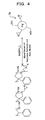
- Fig. 4 is a view illustrating the method of preparing the PI palladium catalyst used in Example 1.
- the micro-encapsulated PI palladium catalyst 5a was prepared by using three kinds of monomers, by bridging reaction mixing the polymer made up in their ratio 91:5:4 with tetrakis(triphenylphosphin) palladium in a solvent mixture of methylene dichloride and amyl alcohol, and heating at about 150°C.
- Fig.5 is a view illustrating the reaction products from hydrogenation reaction of benzalacetone of Example 1.
- 4-phenyl-2-butanone and 4-phenyl-2-butanol were obtained by hydrogenation of benzalacetone within five minutes as reaction time at the yield of 97% and 3 %, respectively.
- the hydrogenation reaction time of Example 1 was calculated as about five minutes from the whole volume of the micro-channel 4 and the volume flow rate of liquid phase, and its observed value was two minutes. This value of reaction time is about 1/30 compared with about one hour as the ordinary flask reaction.
- Example 2 hydrogenation reaction was conducted under the same condition as Example 1 for THF diluted solution concentration of the substance to be reduced, its flow rate, and hydrogen 9 flow rate, using cyclohexen-2-one as the substance to be reduced.
- the reaction time was within five minutes.
- the reaction product was analyzed by 1 H-NMR.
- Fig. 6 is a view illustrating the yields of hydrogenation reaction of Example 2. As is obvious from the figure, the analytical result of the reaction product by 1 H-NMR showed almost complete hydrogenation of cyclohexen-2-one, and cyclohexanone was obtained at about 100 % yield.
- Example 3 hydrogenation reaction was conducted under the same condition as Example 1 for THF diluted solution concentration of the substance to be reduced, its flow rate, and hydrogen 9 flow rate, using 2,4-diphenyl-4-methyl-1-pentene as the substance to be reduced.
- the reaction time was within five minutes.
- the analytical result of the reaction product by 1 H-NMR showed almost complete hydrogenation of 2,4-diphenyl-4-methyl-1-pentene, and 2,4-diphenyl-2-methylpentane was obtained at about 100 % yield (See Fig. 6 .).
- Example 4 hydrogenation reaction was conducted under the same condition as Example 1 for THF diluted solution concentration of the substance to be reduced, its flow rate, and hydrogen 9 flow rate, using 1,4-diphenyl-1,3-butadiene as the substance to be reduced.
- the reaction time was within five minutes.
- the analytical result of the reaction product by 1 H-NMR showed almost complete hydrogenation of 1,4-diphenyl-1,3-butadiene, and 1,4-diphenylbutane was obtained at about 100 % yield (See Fig. 6 .).
- Example 5 hydrogenation reaction was conducted under the same condition as Example 1 for THF diluted solution concentration of the substance to be reduced, its flow rate, and hydrogen 9 flow rate, using 1,2-diphenylacetylene as the substance to be reduced.
- the reaction time was within five minutes.
- the analytical result of the reaction product by 1 H-NMR showed almost complete hydrogenation of 1,2-diphenylacetylene, and 1,2-diphenylethane was obtained at about 100 % yield (See Fig. 6 .).
- Example 6 hydrogenation reaction was conducted under the same condition as Example 1 for THF diluted solution concentration of the substance to be reduced, its flow rate, and hydrogen 9 flow rate, using 3-phenyl-2-propin-1-ol as the substance to be reduced.
- the reaction time was within five minutes.
- the analytical result of the reaction product by 1 H-NMR showed almost complete hydrogenation of 3-phenyl-2-propin-1-ol, and 3-phenyl-1-propanol was obtained at about 100 % yield (See Fig. 6 .).
- Example 7 hydrogenation reaction was conducted under the same condition as Example 1 for THF diluted solution concentration of the substance to be reduced, its flow rate, and hydrogen 9 flow rate, using 1-phenylcyclohexene as the substance to be reduced.
- the reaction time was within five minutes.
- the analytical result of the reaction product by 1 H-NMR showed almost complete hydrogenation of 1-phenylcyclohexene, and phenylcyclohexane was obtained at 99 % yield (See Fig. 6 .).
- Example 8 nitrobenzene was used as the substance to be reduced.
- Hydrogenation reaction of nitrobenzene was conducted by supplying ethanol diluted solution 7 of the substance to be reduced (concentration was 0.1 mole %/1000cm 3 ) and hydrogen gas at flow rates 0.1 cm 3 /hour and 1 cm 3 /minute, respectively, and passing the substance to be reduced and hydrogen 9 through the micro-channel 4 in pipe flow state. Other conditions were same as Example 1, and the reaction time was within five minutes. The reaction was conducted at room temperature. The analytical result of the reaction product by a gas chromatography apparatus showed hydrogenation of nitrobenzene, and aniline was obtained at 82 % yield (See Fig. 6 .).
- Example 9 carbon monoxide insertion reaction was conducted using cinnamyl chloride as the reactant.
- the used catalyst was same as Example 1.
- Basic ethanol diluted solution (sodium salt of p-nitrophenol) of cinnamyl chloride was used.
- concentrations of cinnamyl chloride and sodium salt of p-nitrophenol were 0.125 mole %/1000 cm 3 and 0.188 mole %/1000 cm 3 , respectively.
- the solution 7 containing said cinnamyl chloride as the reactant and carbon monoxide gas 9 were supplied at flow rates 0.1 cm 3 /hour and 2 cm 3 /minute, respectively.
- carbon monoxide insertion reaction that is, cabonylation of cinnamyl chloride was conducted, and ethyl ester of 4-phenyl-3-butenoic acid was obtained.
- the reaction time was within five minutes. The reaction was conducted at room temperature.
- Fig. 7 is a view illustrating the yield of carbonylation reaction of Example 9.
- the analytical result of the reaction product by a gas chromatography apparatus showed carbonylation of cinnamyl chloride, and ethyl ester of 4-phenyl-3-butenoic acid was obtained at 15 % yield.
- Carbon monoxide insertion reaction has low reaction rate in general, and needs high temperature and high pressure in many cases.
- the acceleration of the reaction is considered to be taking place sufficiently, taking into account the reaction condition at room temperature and ordinary pressure, and within five minutes of reaction time.
- reaction since it is three phase reaction of solid - liquid - gas phases as in hydrogenation reaction, the reaction is considered to proceed more efficiently in a micro-channel compared with that in a flask. Thereby, the reaction rate is considered to be remarkably improved by pipe flow as reaction system.
- reaction of hydrogenation of a substance to be reduced and others can be conducted in short time and at good yield. Also in the method of catalytic reaction using a micro-reactor of the present invention, since the consumption of materials of the reactant and gas and power consumption required for their supply and stirring are extremely low, the cost is low compared with the reactions using the conventional reactors. Therefore, three phase catalytic reductive reaction an others needed for the search for medicines and fine chemicals can be conducted at low cost.
Landscapes
- Chemical & Material Sciences (AREA)
- Organic Chemistry (AREA)
- Chemical Kinetics & Catalysis (AREA)
- Engineering & Computer Science (AREA)
- Materials Engineering (AREA)
- Inorganic Chemistry (AREA)
- Organic Low-Molecular-Weight Compounds And Preparation Thereof (AREA)
- Catalysts (AREA)
- Physical Or Chemical Processes And Apparatus (AREA)
- Low-Molecular Organic Synthesis Reactions Using Catalysts (AREA)
Claims (8)
- Verfahren zur katalytischen Umsetzung unter Verwendung eines Mikroreaktors (1), dadurch gekennzeichnet,
dass das Verfahren zur katalytischen Umsetzung einen Mikroreaktor (1) mit einem Metallkatalysator (5) oder einem Metallkomplexkatalysator (5) als feste Phase einsetzt, welche an der inneren Wand (4c) eines Kanals (4) gelagert ist;
dass der Metallkatalysator (5) oder der Metallkomplexkatalysator ein Katalysator ist, welcher in einem Polymer enthalten ist,
dass der in dem Polymer enthaltene Katalysator an der inneren Wand (4c) des Kanals (4) über eine Kovalenzbindung mit einer Gruppe getragen wird, welche an der inneren Wand (4c) des Kanals (4) bereit gestellt ist, oder
dass der in dem Polymer enthaltene Katalysator an der inneren Wand (4c) des Kanals (4) über eine Kovalenzbindung über einen Abstandshalter (4d), welcher mit einer Gruppe der Polymeroberfläche verbunden ist, getragen wird,
dass Wasserstoff (9; 14) in Gasphase entlang des Mittelteils des Kanals geführt wird, und
dass eine Lösung (7; 12) in einer flüssigen Phase, in welcher ein Reaktionsmittel gelöst ist, zwischen dem Wasserstoff (9; 14) und dem Katalysator (5), welcher an der inneren Wand (4c) des Kanals (4) gelagert ist, geführt wird;
wodurch die Reaktion der genannten Lösung (7; 12) und des Wasserstoffs (9; 14) durch die katalytische Dreiphasenreaktion von Fest-, Flüssig-, Gasphasen, welche durch den Metallkatalysator (5) oder den Metallkomplexkatalysator (5) katalysiert werden, durchgeführt wird. - Verfahren zur katalytischen Umsetzung unter Verwendung eines Mikroreaktors (1) nach Anspruch 1, dadurch gekennzeichnet, dass der Metallkatalysator (5) Palladium ist.
- Verfahren zur katalytischen Umsetzung unter Verwendung eines Mikroreaktors (1) nach Anspruch 1, dadurch gekennzeichnet, dass der Metallkatalysator (5) ein Element aus der Gruppe ist, welche Chrom, Mangan, Eisen, Kobalt, Nickel, Kupfer, Molybdän, Ruthenium, Rhodium, Wolfram, Osmium, Iridium und Palladium enthält.
- Verfahren zur katalytischen Umsetzung unter Verwendung eines Mikroreaktors (1) nach Anspruch 1, dadurch gekennzeichnet, dass der Metallkomplexkatalysator (5) ein Palladiumkomplexkatalysator ist.
- Verfahren zur katalytischen Umsetzung unter Verwendung eines Mikroreaktors (1) nach Anspruch 1, dadurch gekennzeichnet, dass der Metallkomplexkatalysator (5) ein Metallkomplexkatalysator aus einem Element der Gruppe ist, welche Chrom, Mangan, Eisen, Kobalt, Nickel, Kupfer, Molybdän, Ruthineum, Rhodium, Wolfram, Osmium, Iridium und Palladium enthält.
- Verfahren zur katalytischen Umsetzung unter Verwendung eines Mikroreaktors (1) nach einem der vorhergehenden Ansprüche, dadurch gekennzeichnet, dass das Abstandshaltermolekül (4d) über eine Kovalenzbindung mit der inneren Wand mittels Si-O-Si-Bindungen verbunden ist.
- Verfahren zur katalytischen Umsetzung unter Verwendung eines Mikroreaktors (1) nach einem der vorhergehenden Ansprüche, dadurch gekennzeichnet, dass das Abstandshaltermolekül (4d) eine funktionale Gruppe trägt, welche mit eine Epoxidgruppe des Polymers verbindbar ist.
- Verfahren zur katalytischen Umsetzung unter Verwendung eines Mikroreaktors (1) nach einem der vorhergehenden Ansprüche, dadurch gekennzeichnet, dass die Gruppe an der inneren Wand (4c) des Kanals (4) entweder eine Silanolgruppe oder eine Aminogruppe ist.
Applications Claiming Priority (2)
| Application Number | Priority Date | Filing Date | Title |
|---|---|---|---|
| JP2004024373 | 2004-01-30 | ||
| PCT/JP2005/001434 WO2005073151A1 (ja) | 2004-01-30 | 2005-01-26 | マイクロリアクターを用いた接触反応方法 |
Publications (3)
| Publication Number | Publication Date |
|---|---|
| EP1726577A1 EP1726577A1 (de) | 2006-11-29 |
| EP1726577A4 EP1726577A4 (de) | 2009-03-04 |
| EP1726577B1 true EP1726577B1 (de) | 2012-11-14 |
Family
ID=34823934
Family Applications (1)
| Application Number | Title | Priority Date | Filing Date |
|---|---|---|---|
| EP05704332A Expired - Lifetime EP1726577B1 (de) | 2004-01-30 | 2005-01-26 | Verfahren zur katalytischen umsetzung unter einsatz eines mikroreaktors |
Country Status (4)
| Country | Link |
|---|---|
| US (1) | US7663008B2 (de) |
| EP (1) | EP1726577B1 (de) |
| JP (1) | JP4605391B2 (de) |
| WO (1) | WO2005073151A1 (de) |
Families Citing this family (26)
| Publication number | Priority date | Publication date | Assignee | Title |
|---|---|---|---|---|
| JP4802521B2 (ja) * | 2004-06-25 | 2011-10-26 | 荒川化学工業株式会社 | マイクロリアクターを用いた接触水素化方法 |
| EP1804964A1 (de) | 2004-10-01 | 2007-07-11 | Velocys Inc. | Mehrphasiges mischverfahren mit mikrokanalverarbeitungstechnologie |
| KR20100038476A (ko) | 2004-11-16 | 2010-04-14 | 벨로시스, 인코포레이티드 | 마이크로채널 기술을 사용하는 다중상 반응 과정 |
| EP1904223A2 (de) | 2005-07-08 | 2008-04-02 | Velocys Inc. | Verfahren für eine katalytische reaktion unter verwendung von mikrokanaltechnologie |
| WO2007099932A1 (ja) * | 2006-03-02 | 2007-09-07 | Inter-University Research Institute Corporation National Institutes Of Natural Sciences | マイクロチャンネルリアクター |
| US7615036B2 (en) † | 2006-05-11 | 2009-11-10 | Kalypto Medical, Inc. | Device and method for wound therapy |
| JP5030222B2 (ja) * | 2006-09-08 | 2012-09-19 | 国立大学法人東京工業大学 | 光触媒系マイクロ反応装置 |
| JP5092443B2 (ja) * | 2007-02-20 | 2012-12-05 | 富士ゼロックス株式会社 | マイクロ流体デバイス、反応装置、及び、反応方法 |
| JP4734544B2 (ja) * | 2007-03-10 | 2011-07-27 | 独立行政法人科学技術振興機構 | キャピラリー及びそれを用いたマイクロリアクター並びに該マイクロリアクターによる固相−液相−気相反応方法 |
| WO2009011904A1 (en) * | 2007-07-19 | 2009-01-22 | Renovis, Inc. | Compounds useful as faah modulators and uses thereof |
| EP2206550B1 (de) | 2007-10-12 | 2016-11-30 | Nippon Soda Co., Ltd. | Mikroreaktor und chemisches flüssigphasenreaktionsverfahren mit dem mikroreaktor |
| JP2009219957A (ja) * | 2008-03-13 | 2009-10-01 | Yamatake Corp | 気液混合システム及び気液混合方法 |
| JP5105285B2 (ja) * | 2008-03-27 | 2012-12-26 | 国立大学法人東京工業大学 | 液体原料の光分解装置及び方法 |
| WO2009118797A1 (ja) * | 2008-03-27 | 2009-10-01 | 国立大学法人東京工業大学 | 二酸化炭素の固定化装置及びその方法 |
| JPWO2010001437A1 (ja) * | 2008-07-01 | 2011-12-15 | 国立大学法人東京工業大学 | 二酸化炭素の固定化装置及びその方法 |
| EP2216093A1 (de) * | 2009-01-30 | 2010-08-11 | Corning Incorporated | Bildung und in situ Abscheidung von Palladium, Pd(0), in Reaktoren |
| JP5413844B2 (ja) * | 2010-02-10 | 2014-02-12 | 国立大学法人東京工業大学 | 芳香族アルデヒド化合物の製造方法 |
| JP5936027B2 (ja) * | 2011-07-20 | 2016-06-15 | Jnc株式会社 | 基質と水素との反応生成物の製造方法 |
| CN108264448B (zh) * | 2017-01-03 | 2019-08-06 | 万华化学集团股份有限公司 | 一种制备β-苯乙醇的反应系统、催化剂及其工艺方法 |
| US20200316555A1 (en) | 2017-12-21 | 2020-10-08 | Hte Gmbh The High Throughput Experimentation Company | Reactor system for continuous flow reactions |
| CN113045384B (zh) * | 2020-11-24 | 2023-01-13 | 上海徽迪皓新材料科技有限公司 | 一种氢化双酚a的连续化制备方法 |
| CN112958097A (zh) * | 2021-02-08 | 2021-06-15 | 清华大学 | 一种用于硝基苯加氢合成苯胺的铜基负载型催化剂及其制备方法 |
| CN113307713A (zh) * | 2021-06-29 | 2021-08-27 | 南京工程学院 | 一种微通道-光催化耦合制备长链烷烃的方法 |
| CN117597191A (zh) * | 2021-07-06 | 2024-02-23 | 株式会社 科特拉 | 气液反应方法 |
| CN115874004B (zh) * | 2022-12-22 | 2024-10-22 | 昆明理工大学 | 一种通过微波辅助气化废弃一次性医用口罩直接还原铁精矿的方法 |
| CN116119741B (zh) * | 2023-02-16 | 2023-11-21 | 四川大学 | 一种镍钴锰三元正极材料前驱体的制备方法 |
Family Cites Families (3)
| Publication number | Priority date | Publication date | Assignee | Title |
|---|---|---|---|---|
| GB9723260D0 (en) * | 1997-11-05 | 1998-01-07 | British Nuclear Fuels Plc | A method of performing a chemical reaction |
| US20040028804A1 (en) * | 2002-08-07 | 2004-02-12 | Anderson Daniel G. | Production of polymeric microarrays |
| EP1547675A1 (de) * | 2003-12-24 | 2005-06-29 | Corning Incorporated | Beschichtete Mikrovorrichtung und deren Herstellungsverfahren |
-
2005
- 2005-01-26 WO PCT/JP2005/001434 patent/WO2005073151A1/ja not_active Ceased
- 2005-01-26 EP EP05704332A patent/EP1726577B1/de not_active Expired - Lifetime
- 2005-01-26 JP JP2005517562A patent/JP4605391B2/ja not_active Expired - Fee Related
- 2005-01-26 US US10/587,895 patent/US7663008B2/en not_active Expired - Fee Related
Also Published As
| Publication number | Publication date |
|---|---|
| WO2005073151A1 (ja) | 2005-08-11 |
| EP1726577A4 (de) | 2009-03-04 |
| JPWO2005073151A1 (ja) | 2007-09-13 |
| US20070161834A1 (en) | 2007-07-12 |
| EP1726577A1 (de) | 2006-11-29 |
| US7663008B2 (en) | 2010-02-16 |
| JP4605391B2 (ja) | 2011-01-05 |
Similar Documents
| Publication | Publication Date | Title |
|---|---|---|
| US7663008B2 (en) | Method of catalytic reaction using micro-reactor | |
| Hessel et al. | Organic synthesis with microstructured reactors | |
| Hessel et al. | Review on patents in microreactor and micro process engineering | |
| Plutschack et al. | The hitchhiker’s guide to flow chemistry∥ | |
| Jähnisch et al. | Chemistry in microstructured reactors | |
| Newman et al. | The role of flow in green chemistry and engineering | |
| Wörz et al. | Microreactors–a new efficient tool for reactor development | |
| Bavykin et al. | Selective oxidation of alcohols in a continuous multifunctional reactor: Ruthenium oxide catalysed oxidation of benzyl alcohol | |
| de Bellefon et al. | High throughput kinetic investigations of asymmetric hydrogenations with microdevices | |
| CA2251693A1 (en) | Supercritical hydrogenation | |
| JP5598952B2 (ja) | マイクロリアクター、およびマイクロリアクターを利用した液相化学反応方法 | |
| Dencic et al. | Recent changes in patenting behavior in microprocess technology and its possible use for gas–liquid reactions and the oxidation of glucose | |
| Makarshin et al. | Microchannel systems for fine organic synthesis | |
| De Bellefon et al. | Asymmetric catalytic hydrogenations at micro-litre scale in a helicoidal single channel falling film micro-reactor | |
| De Bellefon et al. | High-throughput screening of molecular catalysts using automated liquid handling, injection, and microdevices | |
| Exposito et al. | Process intensification of continuous-flow imine hydrogenation in catalyst-coated tube reactors | |
| Guan et al. | High-pressure asymmetric hydrogenation in a customized flow reactor and its application in multi-step flow synthesis of chiral drugs | |
| JP4734544B2 (ja) | キャピラリー及びそれを用いたマイクロリアクター並びに該マイクロリアクターによる固相−液相−気相反応方法 | |
| Venezia et al. | Slurry loop tubular membrane reactor for the catalysed aerobic oxidation of benzyl alcohol | |
| EP1373166A2 (de) | Superkritische hydrierung | |
| JP4734505B2 (ja) | マイクロリアクター及びそれを用いた接触反応方法 | |
| Hönicke | Microchemical reactors for heterogeneously catalyzed reactions | |
| JP2007069164A (ja) | マイクロキャピラリーを用いた反応装置及びそれによる接触水素化反応方法 | |
| Reina et al. | Hydrogenation reactions catalyzed by colloidal palladium nanoparticles under flow regime | |
| JP2009214056A (ja) | キャピラリーとキャピラリーへの触媒固定化方法、並びにマイクロリアクターとこれを用いた固相−液相−気相反応方法 |
Legal Events
| Date | Code | Title | Description |
|---|---|---|---|
| PUAI | Public reference made under article 153(3) epc to a published international application that has entered the european phase |
Free format text: ORIGINAL CODE: 0009012 |
|
| 17P | Request for examination filed |
Effective date: 20060831 |
|
| RBV | Designated contracting states (corrected) |
Designated state(s): DE FR GB |
|
| DAX | Request for extension of the european patent (deleted) | ||
| RBV | Designated contracting states (corrected) |
Designated state(s): DE FR GB |
|
| RBV | Designated contracting states (corrected) |
Designated state(s): DE FR GB |
|
| A4 | Supplementary search report drawn up and despatched |
Effective date: 20090204 |
|
| 17Q | First examination report despatched |
Effective date: 20091204 |
|
| GRAP | Despatch of communication of intention to grant a patent |
Free format text: ORIGINAL CODE: EPIDOSNIGR1 |
|
| GRAS | Grant fee paid |
Free format text: ORIGINAL CODE: EPIDOSNIGR3 |
|
| GRAA | (expected) grant |
Free format text: ORIGINAL CODE: 0009210 |
|
| AK | Designated contracting states |
Kind code of ref document: B1 Designated state(s): DE FR GB |
|
| REG | Reference to a national code |
Ref country code: DE Ref legal event code: R096 Ref document number: 602005036958 Country of ref document: DE Effective date: 20130110 |
|
| PLBE | No opposition filed within time limit |
Free format text: ORIGINAL CODE: 0009261 |
|
| STAA | Information on the status of an ep patent application or granted ep patent |
Free format text: STATUS: NO OPPOSITION FILED WITHIN TIME LIMIT |
|
| 26N | No opposition filed |
Effective date: 20130815 |
|
| REG | Reference to a national code |
Ref country code: DE Ref legal event code: R097 Ref document number: 602005036958 Country of ref document: DE Effective date: 20130815 |
|
| REG | Reference to a national code |
Ref country code: FR Ref legal event code: PLFP Year of fee payment: 12 |
|
| PGFP | Annual fee paid to national office [announced via postgrant information from national office to epo] |
Ref country code: GB Payment date: 20151214 Year of fee payment: 12 |
|
| PGFP | Annual fee paid to national office [announced via postgrant information from national office to epo] |
Ref country code: FR Payment date: 20151214 Year of fee payment: 12 |
|
| PGFP | Annual fee paid to national office [announced via postgrant information from national office to epo] |
Ref country code: DE Payment date: 20151211 Year of fee payment: 12 |
|
| REG | Reference to a national code |
Ref country code: DE Ref legal event code: R119 Ref document number: 602005036958 Country of ref document: DE |
|
| GBPC | Gb: european patent ceased through non-payment of renewal fee |
Effective date: 20170126 |
|
| REG | Reference to a national code |
Ref country code: FR Ref legal event code: ST Effective date: 20170929 |
|
| PG25 | Lapsed in a contracting state [announced via postgrant information from national office to epo] |
Ref country code: FR Free format text: LAPSE BECAUSE OF NON-PAYMENT OF DUE FEES Effective date: 20170131 |
|
| PG25 | Lapsed in a contracting state [announced via postgrant information from national office to epo] |
Ref country code: DE Free format text: LAPSE BECAUSE OF NON-PAYMENT OF DUE FEES Effective date: 20170801 Ref country code: GB Free format text: LAPSE BECAUSE OF NON-PAYMENT OF DUE FEES Effective date: 20170126 |